Loading ...
Loading ...
Loading ...
Page 13
OPERATION
WARNING:
Only use accessories
that comply with the size marked on the
tool.
WARNING:
Only use accessories
with a Maximum Safe Operating Speed
rated at least equal to the maximum
speed marked on the tool.
TO REMOVE THE GRINDING/
CUTTING WHEEL (FIG. 4 / 5)
1. Remove the battery pack.
2. Depress the spindle-lock button
and loosen the lock nut by turning it
counterclockwise with the wrench.
3. Remove the lock nut and remove the
grinding/cutting wheel.
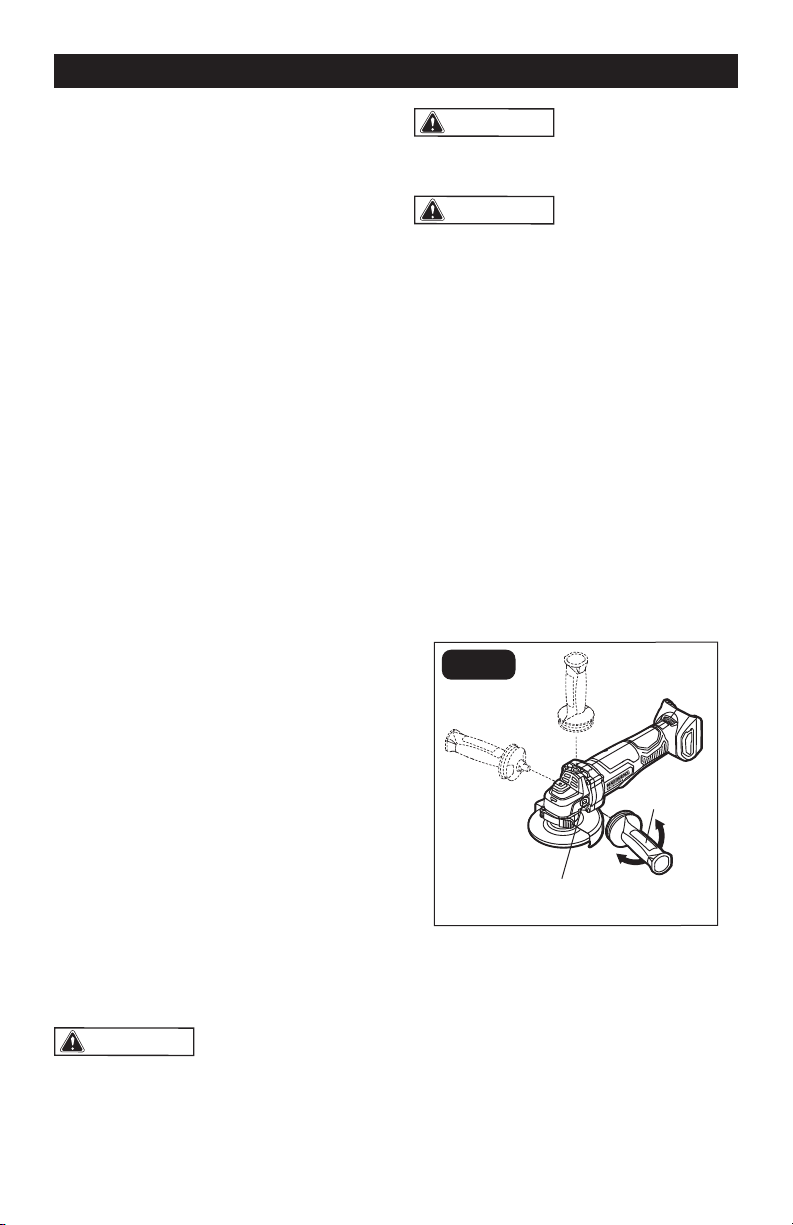
TO INSTALL/REMOVE THE AUX-
ILIARY HANDLE (FIG. 6)
FIG. 6
Auxiliary-Handle
Socket
Auxiliary-
Handle
This angle grinder/cut-off tool is equipped
with an auxiliary handle. The handle can
be installed in any of three auxiliary-handle
sockets. For ease of operation, position the
auxiliary handle in the location that offers
the best control and guard protection.
1. To install the auxiliary handle, remove
the battery pack, then thread the
auxiliary handle into the auxiliary-handle
socket and tighten the handle securely
by turning it clockwise.
The grinding wheel or cutting wheel (not
included) can be mounted on this tool. The
following is the installation tutorial for both
wheels.
1. Remove the battery pack.
2. Depress the spindle-lock button, loosen
the lock nut with the supplied wrench.
Remove the locking nut and the backing
ange.
3. Wipe the spindle, locking nut and
backing ange to remove dust and
debris. Inspect the parts for damage.
Replace if needed.
4. Properly position the grinding or cutting
guard.
5. Place the backing ange on the spindle
and align it with the spindle, make sure
that the backing ange is positioned
so that the shape of the opening in the
ange corresponds with the shape at the
base of the spindle.
6. Place the grinding or cutting wheel on
the spindle and align it with the backing
ange. Always install the grinding wheel
with the depressed center against the
backing ange.
7. When installing the grinding wheel,
position the lock nut so that the raised,
small diameter portion of the lock nut
faces the hole in the grinding wheel (FIG.
4). When installing the cutting wheel,
position the lock nut so that the at
surface faces the cutting wheel (FIG. 5).
8. Thread the lock nut onto the spindle.
9. Depress the spindle-lock button and
tighten the wheel securely by turning the
lock nut clockwise using the wrench.
NOTICE:
Use grinding guard only with grinding
wheels. Use cutting guard only with cutting
wheels.
Use only Type 27 grinding wheels with the
diameter of 4-1/2” (115 mm), 5” (125 mm)
and thickness of 1/4” (6 mm).
Use only Type 41 cutting wheels.
WARNING:
Do not reverse the lock
nut. If the lock nut is not installed properly,
the wheel cannot be tightened properly,
which can result in possibly serious injury.
Loading ...
Loading ...
Loading ...