
241-0491
BRUSHLESS
ANGLE GRINDER
For questions / comments, technical assistance or repair parts –
Please Call Toll Free: 1-866-917-4374 (M-F 8:30am-5:00pm EST).
OPERATOR’S MANUAL
CAUTION:
To Reduce The Risk Of Injury, User Must Read And
Understand Operator’s Manual. Save These Instructions For Future
Reference.

TABLE OF CONTENTS
Safety Symbols ......................................................... Page 2
Safety Instructions ...................................................... Page 3
Overview/Specications ................................................. Page 9
Assembly ............................................................ Page 10
Operation ............................................................ Page 11
Maintenance .......................................................... Page 17
Troubleshooting ....................................................... Page 18
Warranty ............................................................. Page 22
Page 2
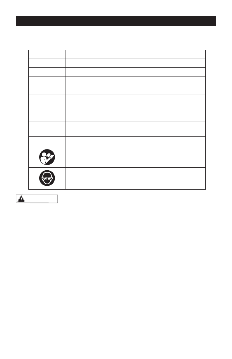
SAFETY SYMBOLS
Some of these following symbols may be used on this tool. Please study them and learn their
meaning. Proper interpretation of these symbols will allow you to operate the tool better and
more safely.
WARNING:
To ensure safety and reliability, all repairs should be performed by a
qualified service technician.
Symbol
Name
Designation / Explanation
V Volts Voltage
A Amperes Current
Hz Hertz Frequency (cycles per second)
W Watts Power
Ibs Pounds Weight
n Rated Speed
Maximum rotational speed with any
recommended accessory installed
…/min or …min
-1
Revolutions per
minute
Unit of speed
�
or d.c.
Direct current Type or a characteristic of current
Read instruction
manual
To reduce the risk of injury, user must
read instruction manual.
Wear safety goggles
To reduce the risk of injury, always
wear eye protection.

Page 3
The purpose of safety symbols is to attract your attention to possible dangers. The
safety symbols, and the explanations with them, deserve your careful attention and
understanding. The symbol warnings do not, by themselves, eliminate any danger. The
instructions and warnings they give are no substitutes for proper accident prevention
measures.
WARNING:
Be sure to read and understand all safety instructions in this manual,
including all safety alert symbols such as “DANGER,” “WARNING,” and “CAUTION”
before using this tool. Failure to follow all instructions listed below may result in electric
shock, fire, and/or serious personal injury.
SYMBOL MEANING
SAFETY ALERT SYMBOL: Indicates DANGER, WARNING, or CAUTION.
May be used in conjunction with other symbols or pictographs.
DANGER:
Indicates an imminently hazardous situation, which, if not avoided,
will result in death or serious injury.
WARNING:
Indicates a potentially hazardous situation, which, if not avoided,
could result in death or serious injury.
CAUTION:
Indicates a potentially hazardous situation, which, if not avoided,
could result in minor or moderate injury.
NOTICE:
(Without Safety Alert Symbol) Indicates a situation that may result in property
damage.
SAVE THESE INSTRUCTIONS!
SAFETY INSTRUCTIONS

Page 4
GENERAL POWER TOOL SAFETY
WARNINGS
WARNING:
Read all safety
warnings, instructions, illustrations and
specifications provided with this power
tool. Failure to follow all instructions listed
below may result in electric shock, re and/or
serious injury.
SAVE ALL WARNINGS AND INSTRUC-
TIONS FOR FUTURE REFERENCE.
The term “power tool” in the warnings refers
to your mains-operated (corded) power tool
or battery-operated (cordless) power tool.
WORK AREA SAFETY
1. Keep work area clean and well lit.
Cluttered or dark areas invite accidents.
2. Do not operate power tools in explosive
atmospheres, such as in the presence
of flammable liquids, gases or dust.
Power tools create sparks which may
ignite the dust or fumes.
3. Keep children and bystanders away
while operating a power tool. Distractions
can cause you to lose control.
ELECTRICAL SAFETY
1. Power tool plugs must match the outlet.
Never modify the plug in any way. Do
not use any adapter plugs with earthed
(grounded) power tools. Unmodied
plugs and matching outlets will reduce
risk of electric shock.
2. Avoid body contact with earthed or
grounded surfaces, such as pipes,
radiators, ranges and refrigerators.
There is an increased risk of electric
shock if your body is earthed or
grounded.
3. Do not expose power tools to rain or
wet conditions. Water entering a power
tool will increase the risk of electric
shock.
4. Do not abuse the cord. Never use the
cord for carrying, pulling or unplugging
the power tool. Keep cord away from
heat, oil, sharp edges or moving parts.
Damaged or entangled cords increase
the risk of electric shock.
5. When operating a power tool outdoors,
use an extension cord suitable for
outdoor use. Use of a cord suitable for
outdoor use reduces the risk of electric
shock.
6. If operating a power tool in a damp
location is unavoidable, use a ground
fault circuit interrupter (GFCI) protected
supply. Use of a GFCI reduces the risk of
electric shock.
PERSONAL SAFETY
1. Stay alert, watch what you are
doing and use common sense when
operating a power tool. Do not use
a power tool while you are tired or
under the influence of drugs, alcohol
or medication. A moment of inattention
while operating power tools may result
in serious personal injury.
2. Use personal protective equipment.
Always wear eye protection. Protective
equipment such as a dust mask, non-
skid safety shoes, hard hat or hearing
protection used for appropriate
conditions will reduce personal injuries.
3. Prevent unintentional starting. Ensure
the switch is in the off-position before
connecting to power source and/or
battery pack, picking up or carrying
the tool. Carrying power tools with your
nger on the switch or energizing power
tools that have the switch on invites
accidents.
4. Remove any adjusting key or wrench
before turning the power tool on.
A wrench or a key left attached to a
rotating part of the power tool may
result in personal injury.
5. Do not overreach. Keep proper footing
and balance at all times. This enables
better control of the power tool in
unexpected situations.
6. Dress properly. Do not wear loose
clothing or jewelry. Keep your hair
and clothing away from moving parts.
Loose clothes, jewelry or long hair can
be caught in moving parts.
7. If devices are provided for the connection
of dust extraction and collection
facilities, ensure these are connected
and properly used. Use of dust collection
can reduce dust-related hazards.
SAFETY INSTRUCTIONS

Page 5
SAFETY INSTRUCTIONS
8. Do not let familiarity gained from frequent
use of tools allow you to become
complacent and ignore tool safety
principles. A careless action can cause
severe injury within a fraction of a second.
POWER TOOL USE AND CARE
1. Do not force the power tool. Use the
correct power tool for your application.
The correct power tool will do the job
better and safer at the rate for which it
was designed.
2. Do not use the power tool if the switch
does not turn it on and off. Any power tool
that cannot be controlled with the switch
is dangerous and must be repaired.
3. Disconnect the plug from the power
source and/or remove the battery
pack, if detachable, from the power
tool before making any adjustments,
changing accessories, or storing
power tools. Such preventive safety
measures reduce the risk of starting the
power tool accidentally.
4. Store idle power tools out of the reach
of children and do not allow persons
unfamiliar with the power tool or these
instructions to operate the power tool.
Power tools are dangerous in the hands
of untrained users.
5. Maintain power tools and accessories.
Check for misalignment or binding of
moving parts, breakage of parts and
any other condition that may affect the
power tool’s operation. If damaged,
have the power tool repaired before
use. Many accidents are caused by
poorly maintained power tools.
6. Keep cutting tools sharp and clean.
Properly maintained cutting tools with
sharp cutting edges are less likely to
bind and are easier to control.
7. Use the power tool, accessories and
tool bits etc. in accordance with these
instructions, taking into account the
working conditions and the work to be
performed. Use of the power tool for
operations different from those intended
could result in a hazardous situation.
8. Keep handles and grasping surfaces
dry, clean and free from oil and grease.
Slippery handles and grasping surfaces
do not allow for safe handling and control
of the tool in unexpected situations.
BATTERY TOOL USE AND CARE
1. Recharge only with the charger
specified by the manufacturer. A
charger that is suitable for one type of
battery pack may create a risk of re
when used with another battery pack.
2. Use power tools only with specifically
designated battery packs. Use of any
other battery packs may create a risk of
injury and re.
3. When battery pack is not in use, keep
it away from other metal objects, like
paper clips, coins, keys, nails, screws
or other small metal objects, that can
make a connection from one terminal to
another. Shorting the battery terminals
together may cause burns or a re.
4. Under abusive conditions, liquid may
be ejected from the battery; avoid
contact. If contact accidentally occurs,
flush with water. If liquid contacts
eyes, additionally seek medical help.
Liquid ejected from the battery may
cause irritation or burns.
5. Do not use a battery pack or tool that
is damaged or modified. Damaged
or modied batteries may exhibit
unpredictable behavior resulting in re,
explosion or risk of injury.
6. Do not expose a battery pack or tool
to fire or excessive temperature.
Exposure to re or temperature above
130 °C (265 °F) may cause explosion.
7. Follow all charging instructions and
do not charge the battery pack or
tool outside the temperature range
specified in the instructions. Charging
improperly or at temperatures outside
the specied range may damage the
battery and increase the risk of re.
SERVICE
1. Have your power tool serviced by
a qualified repair person using only
identical replacement parts. This will
ensure that the safety of the power tool
is maintained.
2. Never service damaged battery packs.
Service of battery packs should only
be performed by the manufacturer or
authorized service providers.

Page 6
SAFETY INSTRUCTIONS
SAFETY WARNINGS COMMON
FOR GRINDING, CUTTING-OFF
OPERATIONS
1. This power tool is intended to function
as a grinder or cut-off tool. Read
all safety warnings, instructions,
illustrations and specifications
provided with this power tool. Failure
to follow all instructions listed below
may result in electric shock, re and/or
serious injury.
2. Operations such as sanding, wire
brushing or polishing are not
recommended to be performed with
this power tool. Operations for which the
power tool was not designed may create
a hazard and cause personal injury.
3. Do not use accessories which
are not specifically designed and
recommended by the tool manufacturer.
Just because the accessory can be
attached to your power tool, it does not
assure safe operation.
4. The rated speed of the accessory
must be at least equal to the maximum
speed marked on the power tool.
Accessories running faster than their
rated speed can break and y apart.
5. The outside diameter and the thickness
of your accessory must be within the
capacity rating of your power tool.
Incorrectly sized accessories cannot be
adequately guarded or controlled.
6. The arbor size of wheels, flanges,
backing pads or any other accessory
must properly fit the spindle of the
power tool. Accessories with arbor
holes that do not match the mounting
hardware of the power tool will run out
of balance, vibrate excessively and
may cause loss of control.
7. Do not use a damaged accessory.
Before each use, inspect the
accessory such as abrasive wheels
for chips and cracks, backing pad for
cracks, tear or excess wear, wire brush
for loose or cracked wires. If power
tool or accessory is dropped, inspect
for damage or install an undamaged
accessory. After inspecting and
installing an accessory, position
yourself and bystanders away from
the plane of the rotating accessory
and run the power tool at maximum
no-load speed for one minute.
Damaged accessories will normally
break apart during this test time.
8. Wear personal protective equipment.
Depending on application, use face
shield, safety goggles or safety
glasses. As appropriate, wear dust
mask, hearing protectors, gloves and
workshop apron capable of stopping
small abrasive or workpiece fragments.
The eye protection must be capable
of stopping ying debris generated by
various operations. The dust mask or
respirator must be capable of ltrating
particles generated by your operation.
Prolonged exposure to high intensity
noise may cause hearing loss.
9. Keep bystanders a safe distance away
from work area. Anyone entering
the work area must wear personal
protective equipment. Fragments of
workpiece or of a broken accessory
may y away and cause injury beyond
immediate area of operation.
10. Hold the power tool by insulated
gripping surfaces only, when
performing an operation where the
cutting tool may contact hidden wiring.
Contact with a “live” wire will also make
exposed metal parts of the power tool
“live” and could give the operator an
electric shock.
11. Never lay the power tool down until
the accessory has come to a complete
stop. The spinning accessory may grab
the surface and pull the power tool out
of your control.
12. Do not run the power tool while carrying
it at your side. Accidental contact with
the spinning accessory could snag your
clothing, pulling the accessory into your
body.
13. Regularly clean the power tool’s air
vents. The motor’s fan will draw the
dust inside the housing and excessive
accumulation of powdered metal may
cause electrical hazards.
14. Do not operate the power tool near
flammable materials. Sparks could
ignite these materials.
15. Do not use accessories that require
liquid coolants. Using water or other
liquid may result in electrocution or
shock.

Page 7
SAFETY INSTRUCTIONS
FURTHER SAFETY INSTRUCTIONS
FOR ALL OPERATIONS
KICKBACK AND RELATED
WARNINGS
Kickback is a sudden reaction to a pinched
or snagged rotating wheel, backing pad,
brush or any other accessory. Pinching
or snagging causes rapid stalling of the
rotating accessory which in turn causes
the uncontrolled power tool to be forced in
the direction opposite of the accessory’s
rotation at the point of the binding.
For example, if an abrasive wheel is
snagged or pinched by the workpiece, the
edge of the wheel that is entering into the
pinch point can dig into the surface of the
material causing the wheel to climb out or
kick out. The wheel may either jump toward
or away from the operator, depending on
direction of the wheel’s movement at the
point of pinching. Abrasive wheels may also
break under these conditions.
Kickback is the result of power tool misuse
and/or incorrect operating procedures or
conditions and can be avoided by taking
proper precautions as given below.
• Maintain a firm grip on the power
tool and position your body and
arm to allow you to resist kickback
forces. Always use auxiliary handle,
if provided, for maximum control over
kickback or torque reaction during
start-up. The operator can control
torque reactions or kickback forces, if
proper precautions are taken.
• Never place your hand near the
rotating accessory. Accessory may
kickback over your hand.
• Do not position your body in the area
where power tool will move if kickback
occurs. Kickback will propel the tool
in direction opposite to the wheel’s
movement at the point of snagging.
• Use special care when working corners,
sharp edges, etc. Avoid bouncing and
snagging the accessory. Corners, sharp
edges or bouncing have a tendency to
snag the rotating accessory and cause
loss of control or kickback.
• Do not attach a saw chain woodcarving
blade or toothed saw blade. Such
blades create frequent kickback and
loss of control.
SAFETY WARNINGS SPECIFIC
FOR GRINDING AND ABRASIVE
CUTTING-OFF OPERATIONS
• Use only wheel types that are
recommended for your power tool and
the specific guard designed for the
selected wheel. Wheels for which the
power tool was not designed cannot be
adequately guarded and are unsafe.
• The grinding surface of center
depressed wheels must be mounted
below the plane of the guard lip.
An improperly mounted wheel that
projects through the plane of the guard
lip cannot be adequately protected.
• The guard must be securely attached
to the power tool and positioned for
maximum safety, so the least amount
of wheel is exposed towards the
operator. The guard helps to protect the
operator from broken wheel fragments,
accidental contact with wheel, and
sparks that could ignite clothing.
• Wheels must be used only for
recommended applications. For
example: do not grind with the side of
cut-off wheel. Abrasive cut-off wheels
are intended for peripheral grinding;
side forces applied to these wheels
may cause them to shatter.
• Always use undamaged wheel flanges
that are of correct size and shape for
your selected wheel. Proper wheel
anges support the wheel thus reducing
the possibility of wheel breakage.
Flanges for cut-off wheels may be
different from grinding wheel anges.
• Do not use worn down wheels from
larger power tools. Wheel intended for
larger power tool is not suitable for the
higher speed of a smaller tool and may
burst.
ADDITIONAL SAFETY WARNINGS
SPECIFIC FOR ABRASIVE
CUTTING-OFF OPERATIONS
• Do not “jam” the cut-off wheel or apply
excessive pressure. Do not attempt
to make an excessive depth of cut.
Overstressing the wheel increases the
Page 8
SAFETY INSTRUCTIONS
loading and susceptibility to twisting
or binding of the wheel in the cut and
the possibility of kickback or wheel
breakage.
• Do not position your body in line with
and behind the rotating wheel. When
the wheel, at the point of operation,
is moving away from your body, the
possible kickback may propel the
spinning wheel and the power tool
directly at you.
• When wheel is binding or when
interrupting a cut for any reason, switch
off the power tool and hold the power
tool motionless until the wheel comes
to a complete stop. Never attempt to
remove the cut-off wheel from the cut
while the wheel is in motion, otherwise
kickback may occur. Investigate and
take corrective action to eliminate the
cause of wheel binding.
• Do not restart the cutting operation
in the workpiece. Let the wheel reach
full speed and carefully re-enter the
cut. The wheel may bind, walk up or
kickback if the power tool is restarted
in the workpiece.
• Support panels or any oversized
workpiece to minimize the risk of
wheel pinching and kickback. Large
workpieces tend to sag under their own
weight. Supports must be placed under
the workpiece near the line of cut and
near the edge of the workpiece on both
sides of the wheel.
• Use extra caution when making a
“pocket cut” into existing walls or
other blind areas. The protruding
wheel may cut gas or water pipes,
electrical wiring or objects that can
cause kickback.
IMPORTANT SAFETY
INSTRUCTIONS
1. To reduce the risk of electric shock or
damage to the chargers and batteries,
use only with the MASTERFORCE
®
battery packs and chargers listed
below:
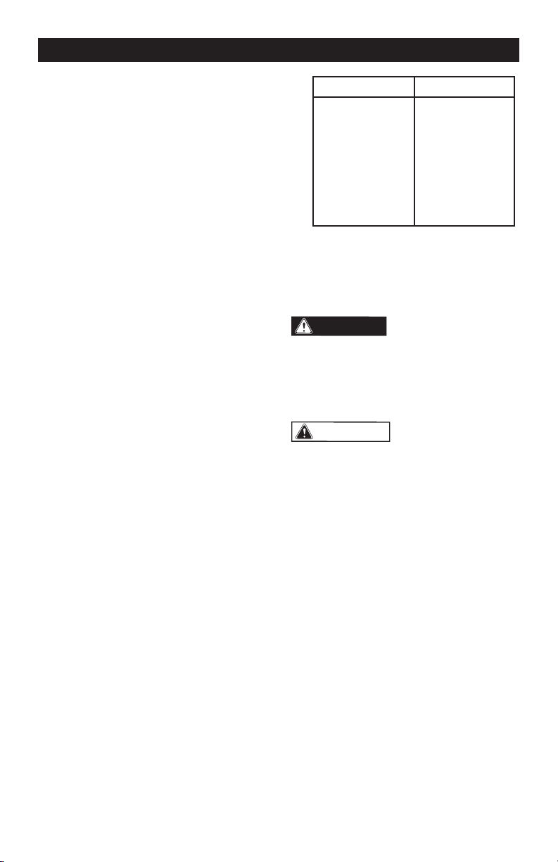
Battery pack Charger
252-8029 (1.5Ah)
252-8031 (2.0Ah)
252-8030 (2.5Ah)
252-8003 (2.5Ah)
252-8034 (4.0Ah)
252-8035 (5.0Ah)
252-8005 (5.0Ah)
252-8027 (7.5Ah)
252-8007 (7.5Ah)
252-8025
252-8037
252-8026
2. For best results, your battery and tool
should be stored, charged and used
in a location where the temperature
is more than 5°C (41°F) but less than
40°C (104°F). Do not store outside or in
vehicles.
DANGER:
People with electronic
devices, such as pacemakers, should
consult their physician(s) before using this
product. Operation of electrical equipment
in close proximity to a heart pacemaker
could cause interference or failure of the
pacemaker.
WARNING:
Some dust created by power sanding, sawing,
grinding, drilling, and other construction
activities contains chemicals known to the
state of California to cause cancer, birth
defects, or other reproductive harm. Some
examples of these chemicals are:
• Lead from lead-based paints
• Crystalline silica from bricks, cement,
and other masonry products
• Arsenic and chromium from chemically-
treated lumber
Your risk from these exposures varies,
depending upon how often you do this type
of work. To reduce your exposure to these
chemicals:
• Work in a well-ventilated area.
• Work with approved safety equipment,
such as dust masks that are specially
designed to lter out microscopic particles.
• Avoid prolonged contact with dust from
power sanding, sawing, grinding, drilling,
and other construction activities. Wear
protective clothing and wash exposed
areas with soap and water. Allowing
dust to get into your mouth or eyes or to
lie on the skin may promote absorption
of harmful chemicals.
Page 9
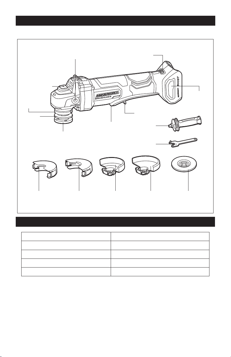
OVERVIEW
Air-inlet
Filter
Auxiliary-Handle Socket
Speed Adjusting Dial
Spindle-Lock
Button
Collar
Backing
Flange
Lock Nut
4-1/2” (115 mm)
Cutting Guard
5” (125 mm)
Cutting Guard
5” (125 mm)
Grinding Guard
Grinding Wheel 4-1/2” (115 mm)
Grinding Guard
Paddle
Switch
Lock-Off Lever
Wrench
Auxiliary
Handle
SPECIFICATIONS
Rated Voltage 20 V d.c.
Rated Speed 3500 - 9000/min
Wheel Diameter 4-1/2" (115 mm) and 5" (125 mm)
Arbor Size 5/8"
Weight (without battery) 3 lbs. 4 oz (1.48kg)

Page 10
ASSEMBLY
WARNING:
If any part is broken or
missing, DO NOT attach the battery pack
or operate the tool until the broken or
missing part is replaced. Failure to do so
could result in possible serious injury.
WARNING:
Do not attempt to
modify this tool or create accessories not
recommended for use with this tool. Any
such alteration or modification is misuse
and could result in a hazardous condition
leading to possible serious injury.
WARNING:
To prevent accidental
starting that could cause serious personal
injury, always remove the battery pack
from the tool when assembling parts,
making adjustments, or cleaning the tool.
CONTENTS
• Cordless angle grinder
• 4-1/2” (115 mm) grinding guard
• 5” (125 mm) grinding guard,
• 4-1/2” (115 mm) cutting guard
• 5” (125 mm) cutting guard
• 4-1/2” (115 mm) grinding wheel
• Wrench
• Auxiliary handle
• Operator’s manual.
UNPACKING
1. Carefully remove the tool and any
accessories from the carton. Make sure
that all items listed in the packing list are
included.
2. Inspect the tool carefully to make sure
that no breakage or damage occurred
during shipping.
3. Do not discard the packing material
until you have carefully inspected and
satisfactorily operated the tool.
Page 11
OPERATION
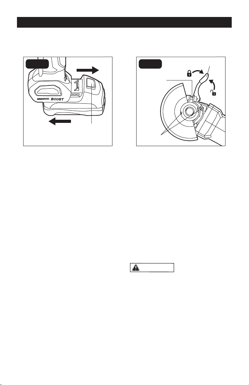
TO ATTACH THE BATTERY PACK
(FIG.1)
FIG. 1
Detach
Attach
Battery-
Release Button
1. Make sure that the angle grinder is
turned off.
2. Align the raised rib on the battery pack
with the grooves on the bottom of the
tool, and then attach the battery pack to
the angle grinder.
3. Pull on the battery pack to make sure it
is securely latched to the tool.
TO DETACH THE BATTERY PACK
(FIG. 1)
1. Make sure that the angle grinder is
turned off.
2. Depress the battery-release button
located on the front of the battery pack
to release the battery pack.
3. Pull the battery pack forward to remove
it from the tool.
TO INSTALL/REMOVE THE
GRINDING GUARD (FIG. 2)
FIG. 2
Tabs
Adjusting
Screw
Guard Lever
This tool is shipped with two types of guards.
A dedicated guard must be used when using
the tool as a grinder or as a cut-off tool.
To Install the Guard:
1. Remove the battery pack and remove
any accessory from the spindle.
2. Open the guard lever to release the
guard.
3. Align the tabs on the guard with the slots
in the grinder gear-box collar and lower
the guard until the guard can rotate
freely in the groove in the collar.
4. Rotate the guard to a suitable position
so that the guard is positioned between
the spindle and the operator to provide
maximum operator protection.
5. Lock the guard in place by pulling the
guard lever.
WARNING:
Keep the guard
between you and the wheel. Do not direct
the guard opening toward your body.
To Remove the Guard:
1. Remove the battery pack and remove
any accessory from the spindle.
2. Open the guard lever to release the
guard.
3. Rotate the guard to the position where
the tabs on the guard align with the slots
in the gear-box collar.
4. Lift the guard straight up and remove it
from the tool.
Page 12
OPERATION
TO ADJUST THE GUARD (FIG. 2)
To adjust the guard, keep the guard lever
open, then rotate the guard to a suitable
position so that the guard is positioned
where it can provide maximum operator
protection, then close the lever to lock the
guard in place.
NOTICE: Use only grinding wheels of the
specified size with the grinding guard. Use
only cut-off wheels of the specified size
with the cutting guard.
NOTICE: The guard is pre-adjusted to
the diameter of the gear-box collar at the
factory. If, after a period of time, the guard
becomes loose, tighten the adjusting
screw in the guard with a Phillips-head
screwdriver (not included).
WARNING:
If the guard cannot
be tightened by adjusting the screw, do
not use the tool and take the tool and
the guard to a service center to repair or
replace the guard.
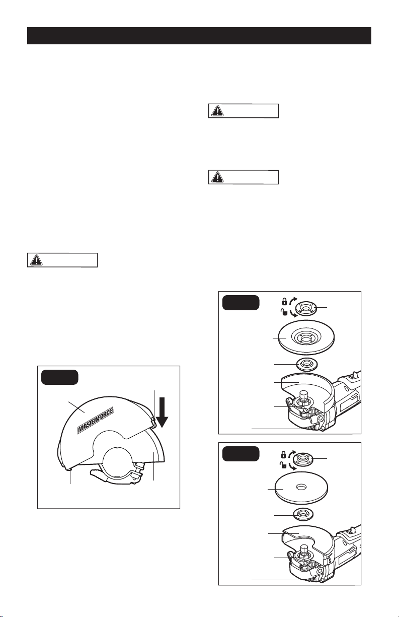
TO INSTALL/REMOVE THE CUT-
TING GUARD (FIG. 3)
FIG. 3
Grinding
Guard
Cutting
Guard
Hook
Hook
1. Remove the battery pack from the angle
grinder.
2. Use the cutting guard to cover the
grinding guard: position one hook of the
cutting guard to engage the grinding
guard, and then push the cutting guard
until the other hook fully engages with
the grinding guard.
3. To remove the cutting guard, use a
at-head screwdriver (not included)
to detach one hook from the grinding
guard, and then the cutting guard can be
pulled out easily.
WARNING:
A guard must be used
when using the tool as a grinder or cut-off
tool. To protect you from serious injury,
never use the grinder with the guard
removed.
WARNING:
Make sure that the
guard lever secures the guard before
operation. Do not direct the guard
opening towards your body.
TO INSTALL THE GRINDING OR
CUTTING WHEEL
(FIG. 4 OR FIG. 5)
FIG. 4
Lock
Nut
Grinding
Wheel
Backing
Flange
Grinding
Guard
Spindle
Spindle-Lock
Button
FIG. 5
Lock
Nut
Cutting
Wheel
Backing
Flange
Cutting
Guard
Spindle
Spindle-Lock
Button
Page 13
OPERATION
WARNING:
Only use accessories
that comply with the size marked on the
tool.
WARNING:
Only use accessories
with a Maximum Safe Operating Speed
rated at least equal to the maximum
speed marked on the tool.
TO REMOVE THE GRINDING/
CUTTING WHEEL (FIG. 4 / 5)
1. Remove the battery pack.
2. Depress the spindle-lock button
and loosen the lock nut by turning it
counterclockwise with the wrench.
3. Remove the lock nut and remove the
grinding/cutting wheel.
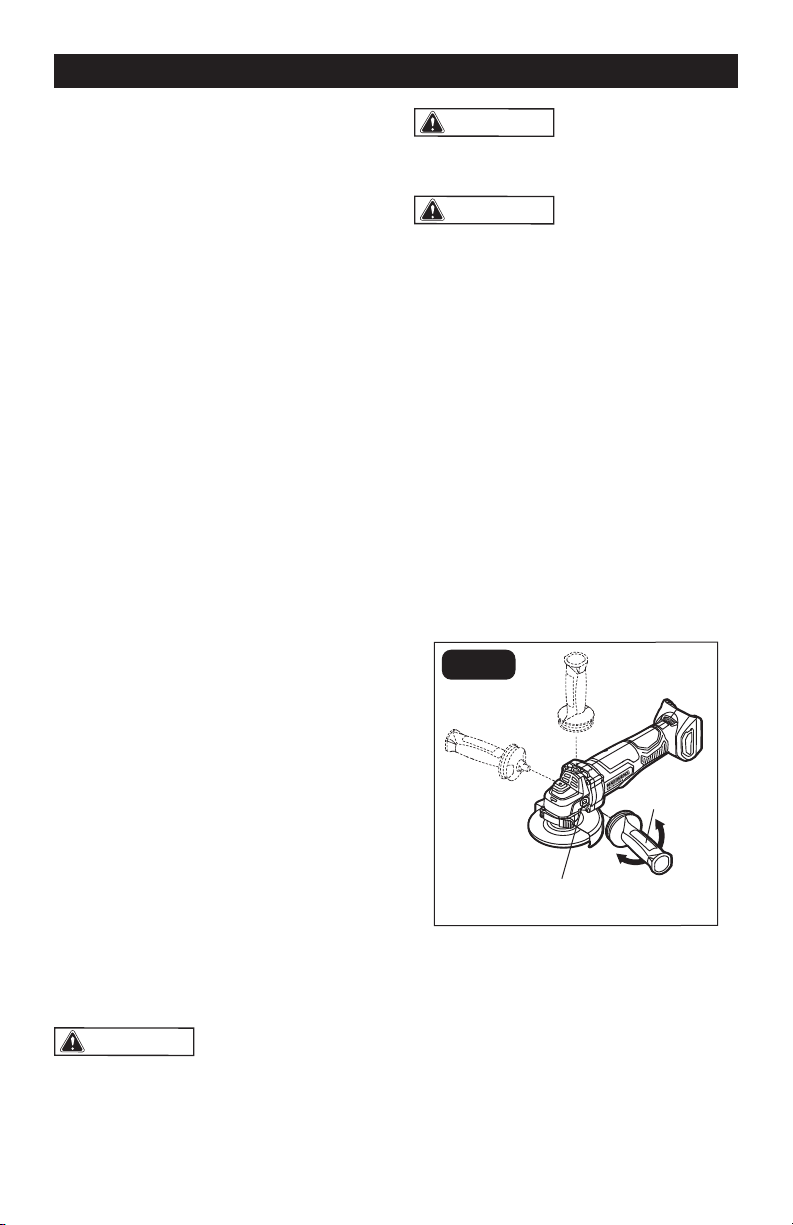
TO INSTALL/REMOVE THE AUX-
ILIARY HANDLE (FIG. 6)
FIG. 6
Auxiliary-Handle
Socket
Auxiliary-
Handle
This angle grinder/cut-off tool is equipped
with an auxiliary handle. The handle can
be installed in any of three auxiliary-handle
sockets. For ease of operation, position the
auxiliary handle in the location that offers
the best control and guard protection.
1. To install the auxiliary handle, remove
the battery pack, then thread the
auxiliary handle into the auxiliary-handle
socket and tighten the handle securely
by turning it clockwise.
The grinding wheel or cutting wheel (not
included) can be mounted on this tool. The
following is the installation tutorial for both
wheels.
1. Remove the battery pack.
2. Depress the spindle-lock button, loosen
the lock nut with the supplied wrench.
Remove the locking nut and the backing
ange.
3. Wipe the spindle, locking nut and
backing ange to remove dust and
debris. Inspect the parts for damage.
Replace if needed.
4. Properly position the grinding or cutting
guard.
5. Place the backing ange on the spindle
and align it with the spindle, make sure
that the backing ange is positioned
so that the shape of the opening in the
ange corresponds with the shape at the
base of the spindle.
6. Place the grinding or cutting wheel on
the spindle and align it with the backing
ange. Always install the grinding wheel
with the depressed center against the
backing ange.
7. When installing the grinding wheel,
position the lock nut so that the raised,
small diameter portion of the lock nut
faces the hole in the grinding wheel (FIG.
4). When installing the cutting wheel,
position the lock nut so that the at
surface faces the cutting wheel (FIG. 5).
8. Thread the lock nut onto the spindle.
9. Depress the spindle-lock button and
tighten the wheel securely by turning the
lock nut clockwise using the wrench.
NOTICE:
Use grinding guard only with grinding
wheels. Use cutting guard only with cutting
wheels.
Use only Type 27 grinding wheels with the
diameter of 4-1/2” (115 mm), 5” (125 mm)
and thickness of 1/4” (6 mm).
Use only Type 41 cutting wheels.
WARNING:
Do not reverse the lock
nut. If the lock nut is not installed properly,
the wheel cannot be tightened properly,
which can result in possibly serious injury.
Page 14
OPERATION
2. To remove the auxiliary handle, remove
the battery pack, then loosen the
auxiliary handle by turning the handle
counterclockwise.
WARNING:
For safety and ease of
operation, securely tighten the auxiliary
handle by turning the handle clockwise
before every use.
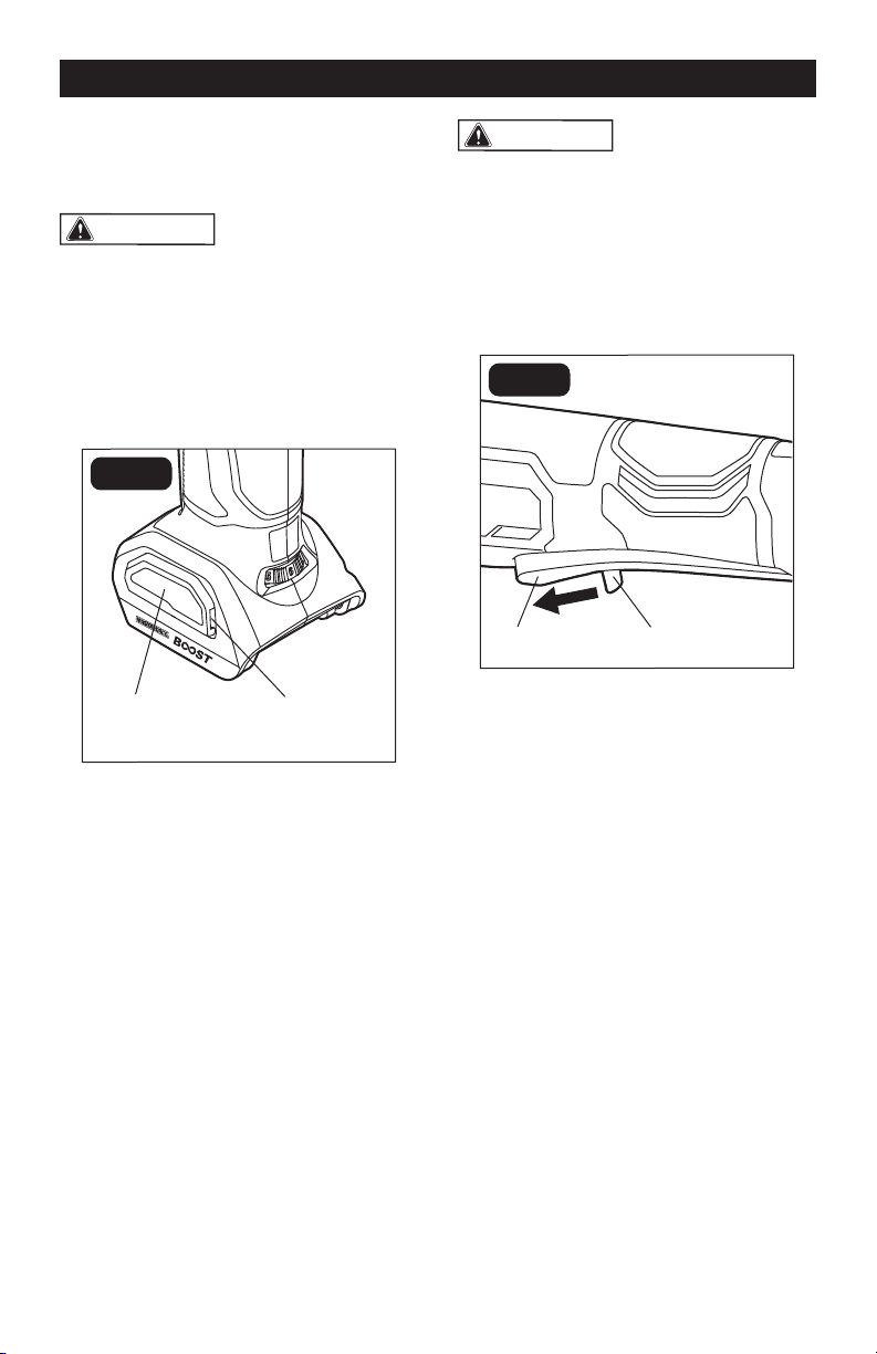
TO INSTALL/REMOVE THE
AIR-INLET FILTER (FIG. 7)
FIG. 7
Air-Inlet Filter
Notch
Using the air-inlet lter will improve the
performance and extend the life of the tool.
1. Remove the battery pack.
2. To install the lter, snap the lter onto the
tool’s foot.
3. To remove the lter, pry the lter away
from the notch with a nger.
4. To clean the lter, tap it against a hard
surface or blow it clean with compressed
air. Always wear safety goggles when
cleaning tools using compressed air.
WARNING:
Always wear safety
goggles or safety glasses with side
shields during power tool operation. If
operation is dusty, also wear a dust mask.
PADDLE SWITCH OPERATION
(FIG. 8)
FIG. 8
Paddle Switch Lock-Off Lever
The angle grinder/cut-off tool is equipped with
a paddle switch to turn the tool on and off.
1. To turn the tool ON, push the lock-off
lever forward and then squeeze the
paddle switch.
2. To turn it OFF, release the paddle switch
and allow it to return to the OFF position.
Make sure that the tool comes to a
complete stop before laying the tool down.
Page 15
OPERATION
SPEED ADJUSTING DIAL (FIG. 9)
FIG. 9
Speed Adjusting Dial
The speed adjusting dial has levels 1
through 6. Before using this tool, turn the
speed adjusting dial to level 1 and then set
the speed adjusting dial to a most suitable
level during the grinding/cutting process.
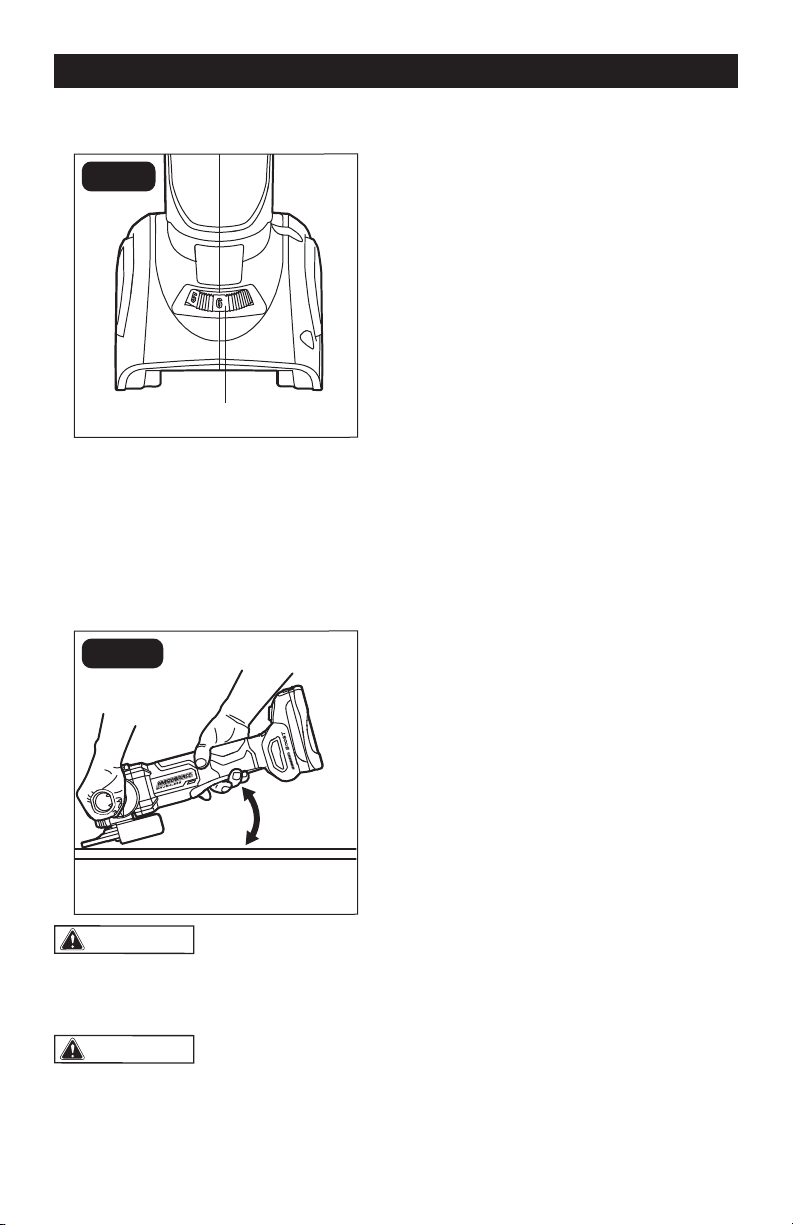
GRINDING (FIG. 10)
FIG. 10
10°– 15°
WARNING:
Do not apply too
much pressure. Too much pressure will
cause the tool to overload and may cause
personal injury.
WARNING:
Sparks are generated
when grinding metal. Make sure that no
combustible material is present or can
come in contact with the flying sparks.
Check the grinding wheels before use.
Discard wheels that have been dropped,
bumped, subjected to extreme changes
in temperature, or have come into contact
with solvents or liquids.
1. Prior to actual use, test the tool by letting
it spin at no load for one minute.
2. Make sure that the workpiece is rmly
clamped in place.
3. Hold the tool securely with both hands.
4. Start the tool.
5. Allow the accessory to reach full speed
before beginning work.
6. For a uniform nish, hold the tool at an
angle of approximately 10° to 15° and
apply constant pressure. Too great an
angle causes concentrated pressure on
small areas, which may gouge or burn
the work surface.
7. Control the pressure and surface contact
between accessory and workpiece.
8. When nished, turn off the tool and
make sure that it comes to a complete
stop before laying it down.
Page 16
OPERATION
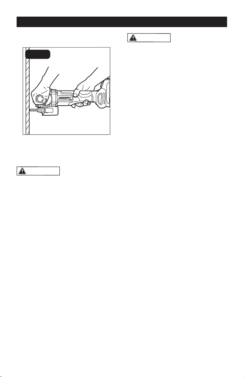
CUTTING (FIG.11)
FIG. 11
Using the cutting guard, it is possible to
perform limited cut-off operations on small
stock such as concrete, metal tubes, piping,
or rebar.
WARNING:
Using the cutting wheel
in a grinding operation will cause the wheel
to crack and break, resulting in serious
personal injury.
WARNING:
The cutting guard
must be installed when using a cutting
wheel to provide maximum protection for
the operator.
When using a cutting wheel, hold the tool
as shown, and use only the edge of the
wheel. Work with moderate feed, adapted
to the material being cut. Do not exert
side pressure onto the cutting wheel, tilt or
oscillate the tool. When cutting proles and
square bar, it is best to start at the smallest
cross section.
Always follow precautions for kickback. Do
not apply side pressure to cutting wheel to
reduce wheel speed. The tool should always
be used so that sparks are directed away
from user.

Page 17
MAINTENANCE
WARNING:
Detach the battery
from the grinder before cleaning or
performing any maintenance.
WARNING:
Always wear safety
goggles or safety glasses with side
shields during power tool operations, or
when blowing dust. If operation is dusty,
also wear a dust mask.
WARNING:
Do not at any time let
brake fluids, gasoline, petroleum-based
products, penetrating oils, etc. come in
contact with plastic parts. Chemicals can
damage, weaken or destroy plastic, which
may result in serious personal injury.
WARNING:
All maintenance should
only be carried out by a qualified service
technician.
CARE OF THE GRINDING AND
CUTTING WHEELS
Grinding and cutting wheels should be
stored in an organized way so that wheels
can be removed without disturbing or
damaging other wheels.
BEFORE EACH USE:
1. Inspect the angle grinder, the paddle
switch and the accessories for damage.
2. Check for damaged, missing, or worn
parts.
3. Check for loose screws, misalignment
or binding of moving parts, or any other
condition that may affect the operation.
4. If abnormal vibration or noise occurs,
turn the tool off immediately and have
the problem corrected before further
use.
CLEANING
Using compressed air may be the most
effective cleaning method. Always wear
safety goggles when cleaning tools using
compressed air. Never use detergent or
alcohol.

Page 18
TROUBLESHOOTING
PROBLEM POSSIBLE CAUSE SOLUTION
The tool does not work. The battery is depleted. Charge the battery.
The tool or the battery
is overloaded.
Decrease the load on the
tool and restart the tool
again.
The tool or the battery
is overheated.
Allow the tool and battery
to cool down and restart
the tool.
Wheel cannot be installed. Wheel is of the wrong
size.
Refer to specication
chart for proper wheel
size.
Auxiliary handle cannot be installed. There is dust in the
auxiliary-handle
sockets.
Clean and clear the
sockets.
Grinding is too slow. The grinding wheel is
worn out.
Replace the grinding
wheel.

Page 19
NOTES

Page 20
NOTES

Page 21
NOTES

Page 22
SAVE YOUR RECEIPTS
THIS WARRANTY IS VOID WITHOUT THEM
BRUSHLESS ANGLE GRINDER
WARRANTY
90-DAY MONEY BACK GUARANTEE:
This MASTERFORCE
®
brand power tool carries our 90-DAY Money Back
Guarantee. If you are not completely satised with your MASTERFORCE
®
brand
power tool for any reason within ninety (90) days from the date of purchase, return
the tool with your original receipt to any MENARDS
®
retail store, and we will provide
you a refund – no questions asked.
3-YEAR LIMITED WARRANTY:
This MASTERFORCE
®
brand power tool carries our famous No Hassle 3-Year
Limited Warranty to the original purchaser. If, during normal use, this
MASTERFORCE
®
power tool breaks or fails due to a defect in material or
workmanship within three (3) years from the date of original purchase, simply bring
this tool with the original sales receipt back to your nearest MENARDS
®
retail store.
At its discretion, MASTERFORCE
®
agrees to have the tool or any defective part(s)
repaired or replaced with the same or similar MASTERFORCE
®
product or part
free of charge, within the stated warranty period, when returned by the original
purchaser with original sales receipt. Not withstanding the foregoing, this limited
warranty does not cover any damage that has resulted from abuse or misuse of the
Merchandise. This warranty: (1) excludes expendable parts including but not limited
to blades, brushes, belts, bits, light bulbs, and/or batteries; (2) shall be void if this
tool is used for commercial and/or rental purposes; and (3) does not cover any
losses, injuries to persons/property or costs. This warranty does give you specic
legal rights and you may have other rights, which vary from state to state. Be
careful, tools are dangerous if improperly used or maintained. Seller’s employees
are not qualied to advise you on the use of this Merchandise. Any oral
representation(s) made will not be binding on seller or its employees. The rights
under this limited warranty are to the original purchaser of the Merchandise and may
not be transferred to any subsequent owner. This limited warranty is in lieu of all
warranties, expressed or implied including warranties or merchantability and tness
for a particular purpose. Seller shall not be liable for any special, incidental, or
consequential damages. The sole exclusive remedy against the seller will be for the
replacement of any defects as provided herein, as long as the seller is willing or
able to replace this product or is willing to refund the purchase price as provided
above. For insurance purposes, seller is not allowed to demonstrate any of these
power tools for you.
For questions / comments, technical assistance or repair parts – Please Call Toll
Free: 1-866-917-4374 (M-F 8:30am-5:00pm EST).

Page 23
11/2020
© 2020 Menard, Inc., Eau Claire, WI 54703