
Angle Grinder
241-0784
OPERATOR’S MANUAL
CAUTION:
To Reduce The Risk Of Injury, User Must Read And
Understand Operator’s Manual. Save These Instructions For
Future Reference.
For questions / comments, technical assistance or repair parts
Please Call Toll Free at: 1-888-686-1484 (M-F 8am – 6pm)

Page 2
TABLE OF CONTENTS
General Safety Rules ..........................................................................3-4
Specific Safety Rules ........................................................................4-6
Symbols ................................................................................................7
General Use Statement .........................................................................8
Specifications .......................................................................................8
Electrical ...............................................................................................9
Features ..............................................................................................10
Operation ....... .............................................................................11-14
Accessories ............. ........................................................................15
Notes ................... .........................................................................16
Warranty ................... .........................................................................17
Customer Service Infor mation .............................................................18

Page 3
PRODUCT SAFETY
WARNING
Some dust created by power
sanding, sawing, grinding, drilling and other
construction activities contains chemicals
known to the state of California to cause
cancer, birth defects or other reproductive
harm. Some examples of these chemicals
are:
● Lead from lead-based paints;
● Crystalline silica from bricks and cement
and other masonry products;
● Arsenic and chromium from chemically-
treated lumber.
Your risk from these exposures varies,
depending on how often you do this type
of work. To reduce your exposure to these
chemical: work in a well ventilated area,
and work with approved safety equipment,
such as those dust masks that are specially
designed to lter out microscopic particles.
WARNING
This product can expose you
to chemicals including lead, phthalate or
bisphenol A which are known to the State of
California to cause cancer, birth defects or
other reproductive harm. Wash your hands
after use. For more information go to www.
P65Warnings.ca.gov.
GENERAL POWER TOOL
SAFETY WARNINGS
WARNING
Read all safety warnings and
instructions. Failure to follow the warnings
and instructions may result in electric shock,
re and/or serious injury.
Save all warnings and instructions for
future reference.
The term power tool in the warnings refers to
your electric (corded) power tool or battery-
operated (cordless) power tool.
WORK AREA SAFETY
• Keep work area clean and well lit.
Cluttered or dark areas invite accidents.
• Do not operate power tools in explosive
atmospheres, such as in the presence of
flammable liquids, gases or dust.Power
tools create sparks which may ignite the dust
or fumes.
.• Keep children and bystanders away
while operating a power tool. Distractions
can cause you to lose control.
ELECTRICAL SAFETY
• Power tool plugs must match the outlet.
Never modify the plug in any way. Do not
use any adapter plugs with grounded power
tools. Unmodied plugs and matching outlets
will reduce risk of electric shock.
• Avoid body contact with grounded
surfaces such as pipes, radiators, ranges
and refrigerators. There is an increased risk
of electric shock if your body is grounded.
• Do not expose power tools to rain or wet
conditions. Water entering a power tool will
increase the risk of electric shock.
• Do not abuse the cord. Never use the
cord for carrying, pulling or unplugging
the power tool. Keep cord away from heat,
oil, sharp edges or moving parts.Damaged
or entangled cords increase the risk of electric
shock.
• When operating a power tool outdoors,
use an extension cord suitable for outdoor
use.Use of a cord suitable for outdoor use
reduces the risk of electric shock.
• If operating a power tool in a damp
location is unavoidable, use a residual
current device (RCD) protected supply. Use
of an RCD reduces the risk of electric shock.
PERSONAL SAFETY
• Stay alert, watch what you are doing
and use common sense when operating a
power tool. Do not use a power tool while
you are tired or under the influence of
drugs, alcohol or medication.A moment of
inattention while operating power tools may
result in serious personal injury.
• Use personal protective equipment.
Always wear eye protection.Protective
equipment such as dust mask, non-skid safety
shoes, hard hat, or hearing protection used
for appropriate conditions will reduce personal
injuries.
• Prevent unintentional starting. Ensure
the switch is in the off-position before
connecting to power source and/or battery
pack, picking up or carrying the tool.
Carrying power tools with your nger on the
switch or energizing power tools that have the
switch on invites accidents.
• Remove any adjusting key or wrench
GENERAL SAFETY RULEs

Page 4
before turning the power tool on.A wrench or
a key left attached to a rotating part of the power
tool may result in personal injury.
• Do not overreach. Keep proper footing
and balance at all times.This enables
better control of the power tool in unexpected
situations.
• Dress properly. Do not wear loose
clothing or jewelry. Keep your hair, clothing
and gloves away from moving parts. Loose
clothes, jewelry or long hair can be caught in
moving parts.
• If devices are provided for the connection
of dust extraction and collection facilities,
ensure these are connected and properly
used. Use of dust collection can reduce dust-
related hazards.
POWER TOOL USE AND CARE
• Do not force the power tool. Use the
correct power tool for your application. The
correct power tool will do the job better and safer
at the rate for which it was designed.
• Do not use the power tool if the switch
does not turn it on and off. Any power tool
that cannot be controlled with the switch is
dangerous and must be repaired.
• Disconnect the plug from the power
source and/or the battery pack from the
power tool before making any adjustments,
changing accessories, or storing power
tools.Such preventive safety measures reduce
the risk of starting the power tool accidentally.
• Store idle power tools out of the reach of
children and do not allow persons unfamiliar
with the power tool or these instructions
to operate the power tool.Power tools are
dangerous in the hands of untrained users.
• Maintain power tools. Check for
misalignment or binding of moving parts,
breakage of parts and any other condition
that may affect the power tools operation.
If damaged, have the power tool repaired
before use.Many accidents are caused by
poorly maintained power tools.
• Keep cutting tools sharp and clean.
Properly maintained cutting tools with sharp
cutting edges are less likely to bind and are
easier to control.
• Use the power tool, accessories and
tool bits etc., in accordance with these
instructions and in the manner intended
for the particular type of power tool, taking
into account the working conditions and
the work to be performed. Use of the power
tool for operations different from those intended
could result in a hazardous situation.
SERVICE
• Have your power tool serviced by a
qualified repair person using only identical
replacement parts. This will ensure that the
safety of the power tool is maintained.
GENERAL SAFETY RULE
SAFETY INSTRUCTIONS FOR ALL
OPERATIONS
Safety Warnings Common for Grinding or
Abrasive Cutting-Off Operations:
• This power tool is intended to function
as a grinder, sander, wire brush, polisher
or cut-off tool. Read all safety warnings,
instructions, illustrations and specifications
provided with this power tool. Failure to
follow all instructions listed below may result in
electric shock, re and/or serious injury.
• Operations such as sanding, wire
brushing, polishing are not recommended
to be performed with this power tool.
Operations for which the power tool was not
designed may create a hazard and cause
personal injury.
• Do not use accessories which are not
specifically designed and recommended
by the tool manufacturer. Just because the
accessory can be attached to your power tool, it
does not assure safe operation.
• The rated speed of the accessory must
be at least equal to the maximum speed
marked on the power tool. Accessories
running faster than their RATED SPEED can
break and y apart.
• The outside diameter and the thickness of
your accessory must be within the capacity
rating of your power tool. Incorrectly sized
accessories cannot be adequately guarded or
controlled.
• Threaded mounting of accessories
must match the GRINDER spindle thread.
For accessories mounted by FLANGES,
the arbour hole of the accessory must

Page 5
fit the locating diameter of the FLANGE.
Accessories that do not match the mounting
hardware of the power tool will run out of balance,
vibrate excessively and may cause loss of control.
• Do not use a damaged accessory. Before
each use inspect the accessory such as
abrasive wheels for chips and cracks,
backing pad for cracks, tear or excess
wear, wire brush for loose or cracked wires.
If power tool or accessory is dropped,
inspect for damage or install an undamaged
accessory. After inspecting and installing an
accessory, position yourself and bystanders
away from the plane of the rotating accessory
and run the power tool at maximum no-load
speed for one minute.Damaged accessories
will normally break apart during this test time.
• Wear personal protective equipment.
Depending on application, use face
shield, safety goggles or safety glasses.
As appropriate, wear dust mask, hearing
protectors, gloves and workshop apron
capable of stopping small abrasive or
workpiece fragments. The eye protection must
be capable of stopping ying debris generated by
various operations. The dust mask or respirator
must be capable of ltrating particles generated
by your operation. Prolonged exposure to high
intensity noise may cause hearing loss.
• Keep bystanders a safe distance away
from work area. Anyone entering the
work area must wear personal protective
equipment.Fragments of workpiece or of a
broken accessory may y away and cause injury
beyond immediate area of operation.
• Hold the power tool by insulated
gripping surfaces only, when performing
an operation where the cutting accessory
may contact hidden wiring or its own cord.
Cutting accessory contacting a “live” wire may
make exposed metal parts of the power tool “live”
and could give the operator an electric shock.
• Position the cord clear of the spinning
accessory. If you lose control, the cord may
be cut or snagged and your hand or arm may be
pulled into the spinning accessory.
• Never lay the power tool down until the
accessory has come to a complete stop.The
spinning accessory may grab the surface and
pull the power tool out of your control.
• Do not run the power tool while carrying it
at your side.Accidental contact with the spinning
accessory could snag your clothing, pulling the
accessory into your body.
• Regularly clean the power tool’s air
vents.The motor’s fan will draw the dust inside
the housing and excessive accumulation of
powdered metal may cause electrical hazards.
• Do not operate the power tool near
flammable materials. Sparks could ignite these
materials.
• Do not use accessories that require liquid
coolants. Using water or other liquid coolants
may result in electrocution or shock.
Further safety instructions for all operations
Kickback and Related Warnings
Kickback is a sudden reaction to a pinched or
snagged rotating wheel, backing pad, brush
or any other accessory. Pinching or snagging
causes rapid stalling of the rotating accessory
which in turn causes the uncontrolled power
tool to be forced in the direction opposite of the
accessory’s rotation at the point of the binding.
For example, if an abrasive wheel is snagged or
pinched by the workpiece, the edge of the wheel
that is entering into the pinch point can dig into
the surface of the material causing the wheel to
climb out or kick out. The wheel may either jump
toward or away from the operator, depending on
direction of the wheel’s movement at the point of
pinching. Abrasive wheels may also break under
these conditions.
Kickback is the result of power tool misuse and/or
incorrect operating procedures or conditions and
canbe avoided by taking proper precautions as
given below.
• Maintain a firm grip on the power tool
and position your body and arm to allow
you to resist kickback forces. Always use
auxiliary handle, if provided, for maximum
control over kickback or torque reaction
during start-up. The operator can control torque
reactions or kickback forces, if proper precautions
are taken.
• Never place your hand near the rotating
accessory.Accessory may kickback over your
hand.
• Do not position your body in the area
where power tool will move if kickback
occurs.Kickback will propel the tool in direction
opposite to the wheel’s movement at the point of
snagging.
• Use special care when working corners,
sharp edges etc. Avoid bouncing and
snagging the accessory. Corners, sharp

Page 6
edges or bouncing have a tendency to snag the
rotating accessory and cause loss of control or
kickback.
• Do not attach a saw chain woodcarving
blade or toothed saw blade. Such blades
create frequent kickback and loss of control.
Additional safety instructions for grinding
and cutting-off operations
Safety Warnings Specific for Grinding and
Abrasive Cutting-Off Operations:
• Use only wheel types that are
recommended for your power tool and the
specific guard designed for the selected
wheel. Wheels for which the power tool was not
designed cannot be adequately guarded and are
unsafe.
• The grinding surface of centre depressed
wheels must be mounted below the plane of
the guard lip. An improperly mounted wheel that
projects through the plane of the guard lip cannot
be adequately protected.
• The guard must be securely attached to
the power tool and positioned for maximum
safety, so the least amount of wheel is
exposed towards the operator.The guard
helps to protect the operator from broken wheel
fragments, accidental contact with wheel and
sparks that could ignite clothing.
• Wheels must be used only for
recommended applications. For example:
do not grind with the side of cut-off wheel.
Abrasive cut-off wheels are intended for
peripheral grinding, side forces applied to these
wheels may cause them to shatter.
• Always use undamaged wheel fIanges
that are of correct size and shape for your
selected wheel.Proper wheel anges support
the wheel thus reducing the possibility of wheel
breakage. anges for cut-off wheels may be
different from grinding wheel fIanges.
• Do not use worn down wheels from
larger power tools.Wheel intended for larger
power tool is not suitable for the higher speed of a
smaller tool and may burst.
Additional safety instructions for cutting-off
operations
Additional Safety Warnings Specific for
Abrasive Cutting-Off Operations:
• Do not jam the cut-off wheel or apply
excessive pressure. Do not attempt to make
an excessive depth of cut. Overstressing the
wheel increases the loading and susceptibility to
twisting or binding of the wheel in the cut and the
possibility of kickback or wheel breakage.
• Do not position your body in line with and
behind the rotating wheel. When the wheel,
at the point of operation, is moving away from
your body, the possible kickback may propel the
spinning wheel and the power tool directly at you.
• When wheel is binding or when
interrupting a cut for any reason, switch
off the power tool and hold the power tool
motionless until the wheel comes to a
complete stop. Never attempt to remove the
cut-off wheel from the cut while the wheel
is in motion otherwise kickback may occur.
Investigate and take corrective action to eliminate
the cause of wheel binding.
• Do not restart the cutting operation in the
workpiece. Let the wheel reach full speed
and carefully reenter the cut. The wheel may
bind, walk up or kickback if the power tool is
restarted in the workpiece.
• Support panels or any oversized
workpiece to minimize the risk of wheel
pinching and kickback. Large workpieces tend
to sag under their own weight. Supports must be
placed under the workpiece near the line of cut
and near the edge of the workpiece on both sides
of the wheel.
• Use extra caution when making a “pocket
cut” into existing walls or other blind areas.
The protruding wheel may cut gas or water
pipes, electrical wiring or objects that can cause
kickback.

Page 7
IMPORTANT: Your power tool and its Instruction Manual may contain “WARNING ICONS” (a
picture symbol intended to alert you to, and/or instruct you as to how to avoid a potentially
hazardous condition). Understanding and heeding these symbols will help you operate your tool
better and safer. Shown below are some of the symbols you may see.
SAVE THESE INSTRUCTIONS
To reduce the risk of injury, user must read instruction manual
Wear eye protection
Wear a dust mask
Wear ear protection
Double insulated
SYMBOLS

Page 8
Do not attempt to use this product until you thoroughly read and completely
understand the instruction manual. Pay close attention to the safety rule, includ-
ing Danger, Warnings, and Cautions.
The operation of any tool can result in foreign objects being thrown into your
eyes, which can result in severe eye damage. Before beginning any operation,
always wear safety goggles or safety glasses with side shields and a full face
shield when needed. We recommend the Wide Vision Safety Mask for use over
your eyeglasses or standard safety glasses with side shields. Always wear eye
protection that complies with ANSI Z87.1.
WARNING
WARNING
GENERAL USE STATEMENT (APPLICATIONS)
Sku: 241-0784
Rated voltage 120V~60Hz
Rated power input 10A
Speed control adjustment 5500-11000/min
Thickness of grinding wheels 5.5mm
Diameter of grinding wheels 125mm
Critical dimensions
Disc size 5"
Disc bore 7/8"
Spindle thread 5/8"-11
Machinery weight 5.06lbs
Protection degree
/II

Page 9
DOUBLE INSULATION
Double insulation is a safety concept for electric power tools, which eliminates
the need for the usual three-wire grounded power cord. All exposed metal parts
are isolated from the internal metal motor components with protecting insulation.
Double insulated tools do not need to be grounded.
WARNING
The double insulated system is intended to protect the user from shock resulting from
a break in the tool’s internal wiring. Observe all normal safety precautions to avoid electrical shock.
IMPORTANT: Servicing a tool with double insulation requires extreme care and knowledge
of the system and should be performed only by a qualied service technician. Always use the
original factory replacement parts when servicing.
ELECTRICAL CONNECTION
The Angle Grinder has a precision-built electric motor. It should be connected to a power supply that
is 120 volts, 60 Hz, AC only (normal household current). Do not operate this tool on direct current (DC).
A substantial voltage drop will cause a loss of power and the motor to overheat. If your tool does not
operate when plugged into an outlet, double-check the power supply.
USE PROPER EXTENSION CORD. Make sure your extension cord is in good condition. When us-
ing an extension cord, be sure to use one heavy enough to carry the current your product will draw.
An undersized cord will cause a drop in line voltage resulting in loss of power and overheating. Table
1 shows the correct size to use depending on cord length and nameplate ampere rating. If in doubt,
use the next heavier gage. The smaller the gage number, the heavier the cord.
Table 1 Minimum gauge for cord
Rating Volts Total length of cord in feet
Ampere 120V 25ft. 50ft. 100 ft. 150 ft.
More Than Not More Than AWG
0
6
10
6
10
12
18
18
16
16
16
16
16
14
14
14
12
12
12 16 14 12 Not Recommended
CAUTION
Keep the extension cord clear of the working area. Position the cord so that it will not get
caught on lumber, tools or other obstructions while you are working with a power tool.
WARNING
Check extension cords before each use. If damaged replace immediately. Never use a tool
with a damaged cord since touching the damaged area could cause electrical shock resulting in serious
injury.
ELECTRICAL
Page 10
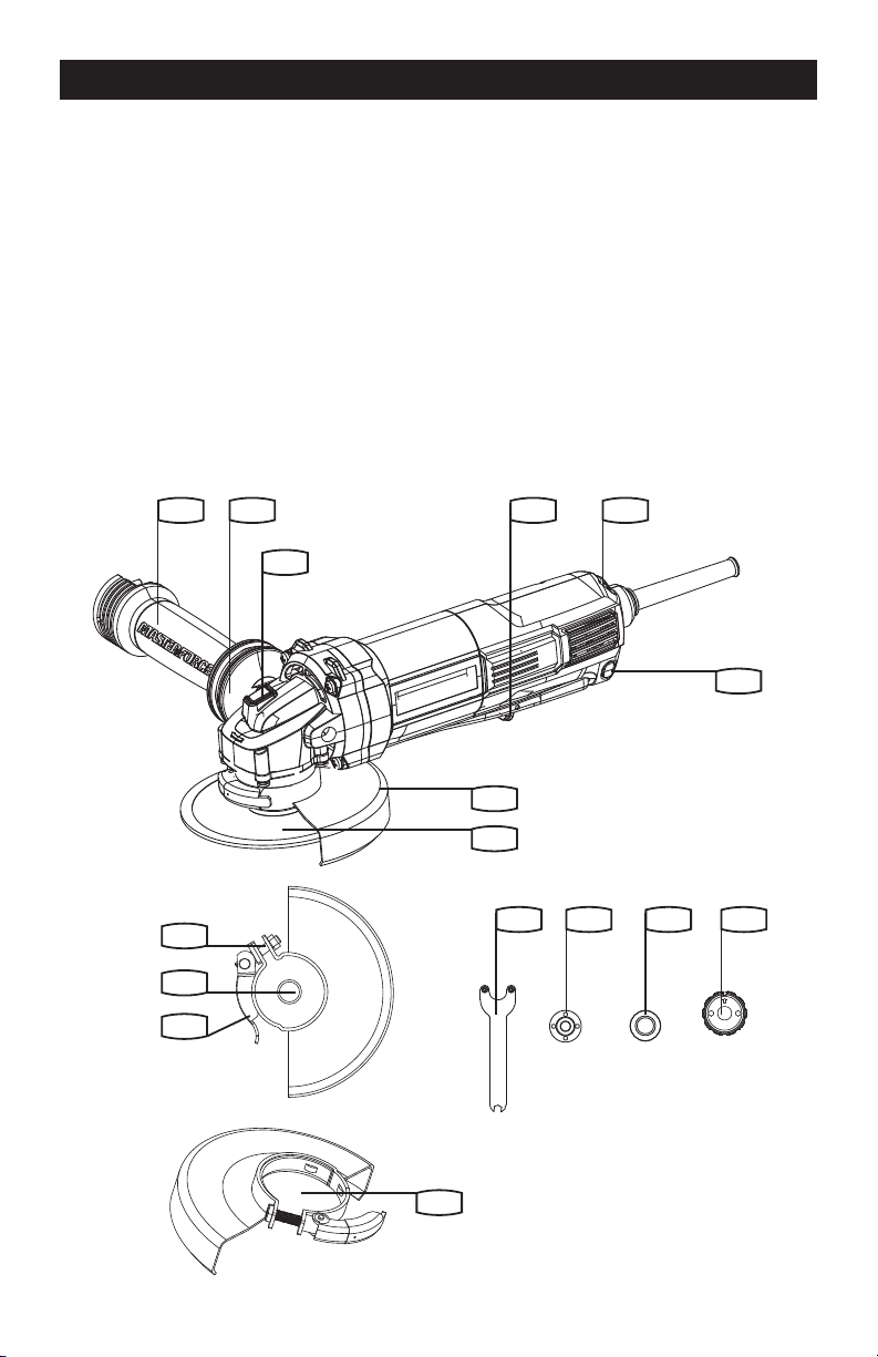
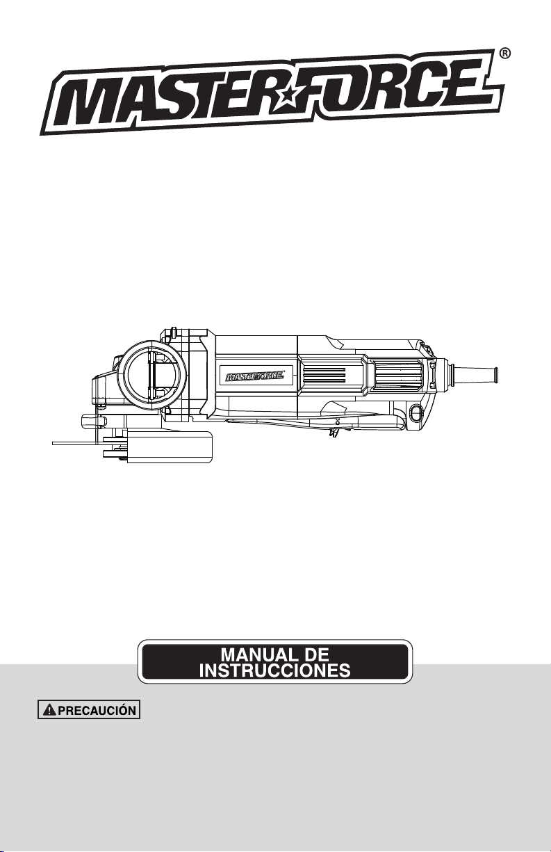
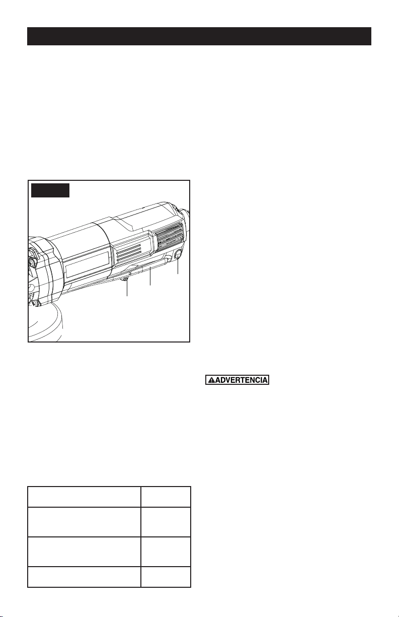
KNOW YOUR ANGLE GRINDER
Before attempting to use any tool, familiarize yourself with all the operating features and safety
requirements.
1. Hand grip areas
2. Anti-vibration auxiliary handle
3. Spindle lock button
4. Disc
5. Wheel guard for grinding
6. Spanner
7. Inner ange
8. Outer ange
9. Clamp adjustment nut
10. Spindle
11. Guard clamping lever
12. Safety on/off switch
13. Variable speed control
14. Wheel guard for cutting*
15. Lock-on button
16. SDS ange
FEATURE
1 12 13
15
5
4
14
2
3
8 76 16
9
10
11
Page 11
OPERATION
OPERATION INSTRUCTIONS
NOTE: Before using the tool, read the
instruction book carefully.
This tool may cause hand-arm vibration
syndrome if its use is not adequately
managed.
Intended Use
The machine is intended for cutting, roughing
and brushing metal and stone materials
without using water. For cutting metal, a special
protection guard for cutting (accessory) must be
used.
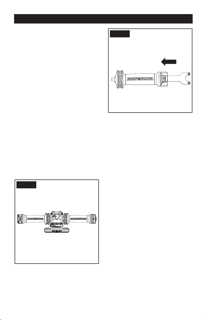
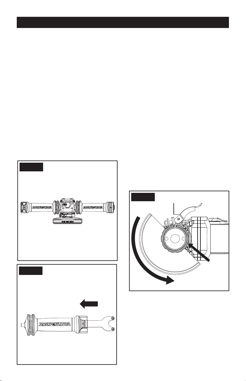
1. INSTALLING THE AUXILIARY HANDLE
(SEE FIG. A1, A2)
You have the option of two working positions to
provide the safest and most comfortable control
of your angle grinder. The handle is screwed
clockwise into either hole on the sides of the gear
case.
Vibration-dampening Auxiliary Handle
The vibration-dampening auxiliary handle
reduces the vibrations, making operation more
comfortable and secure. Your tool is equipped
with an auxiliary handle that can be used for
storage of the spanner. (See Fig. A2)
Fig. A1
Fig. A2
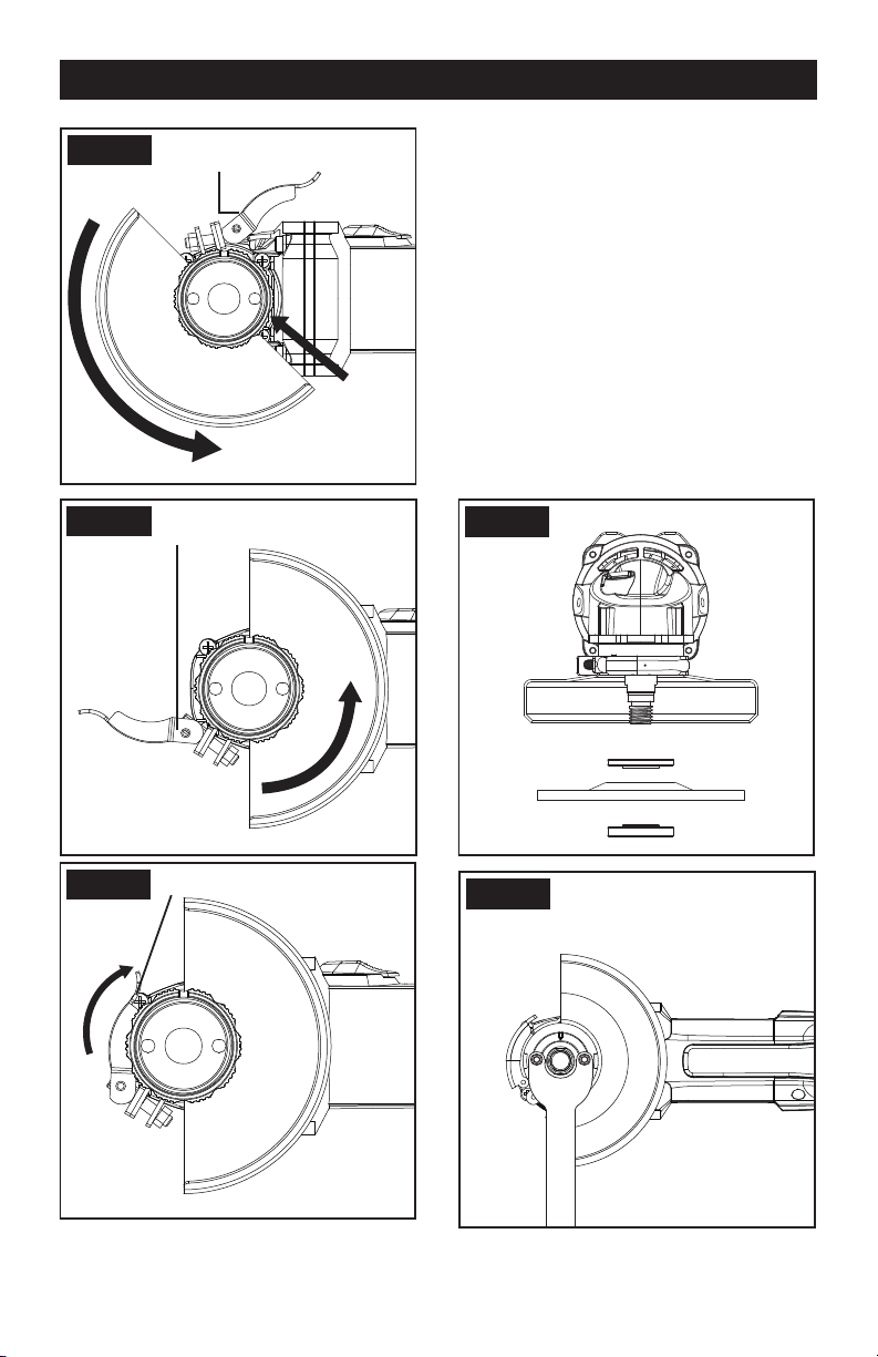
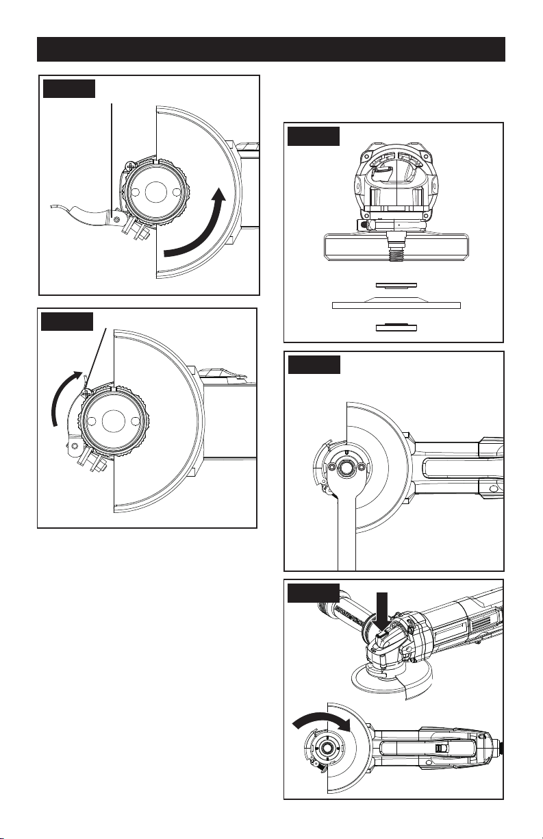
2. INSTALLING AND ADJUSTING THE DISC
GUARD
Make sure the grinder is unplugged before
making any adjustments.
For work with grinding discs, the disc guard must
be mounted.
The projection on the disc guard ensures that
only a guard that ts this angle grinder can be
mounted. Raise the guard clamping lever (See
Fig. B1).
To install the guard align the guard projection
with the matching groove on the spindle housing
(See Fig. B1). Push the guard down as far as it
will go.
Rotate the guard to a working position (See Fig.
B2 example).
NOTE: working position is with the closed side
of the guard toward the operator and open
side pointing directly away from the operator to
provide maximum protection against sparks and
ying debris.
Close the clamping lever to tighten (See Fig. B3
example).
Page 12
OPERATION
Fig. B1
Open Guard Clamping Lever
Insert and Turn
Counterclockwise
Projection
Fig. B2
Working Position (Example)
Opened Guard Clamping Lever
Fig. B3
Working Position (Example)
Closed Guard Clamping Lever
3. FITTING THE DISCS (SEE C1, C2)
Put the inner ange onto the tool spindle. Ensure
it is located on the two ats of spindle.
Place the disc on the tool spindle and inner
ange. Ensure it is correctly located. Fit the
threaded outer ange making sure it is facing in
the correct direction for the type of disc tted.
For grinding discs, the ange is tted with the
raised portion facing towards the disc. For
cutting discs, the ange is tted with the raised
portion facing away from the disc (see C1).
Press in the spindle lock button and rotate the
spindle by hand until it is locked. Keeping the
lock button pressed in, tighten the outer ange
with the spanner provided. (See C2). For SDS
ange, keep the lock button pressed in and
tightened the SDS ange with hand. (See C3)
Fig. C1
Fig. C2
OPERATION
Page 13
Fig. C3
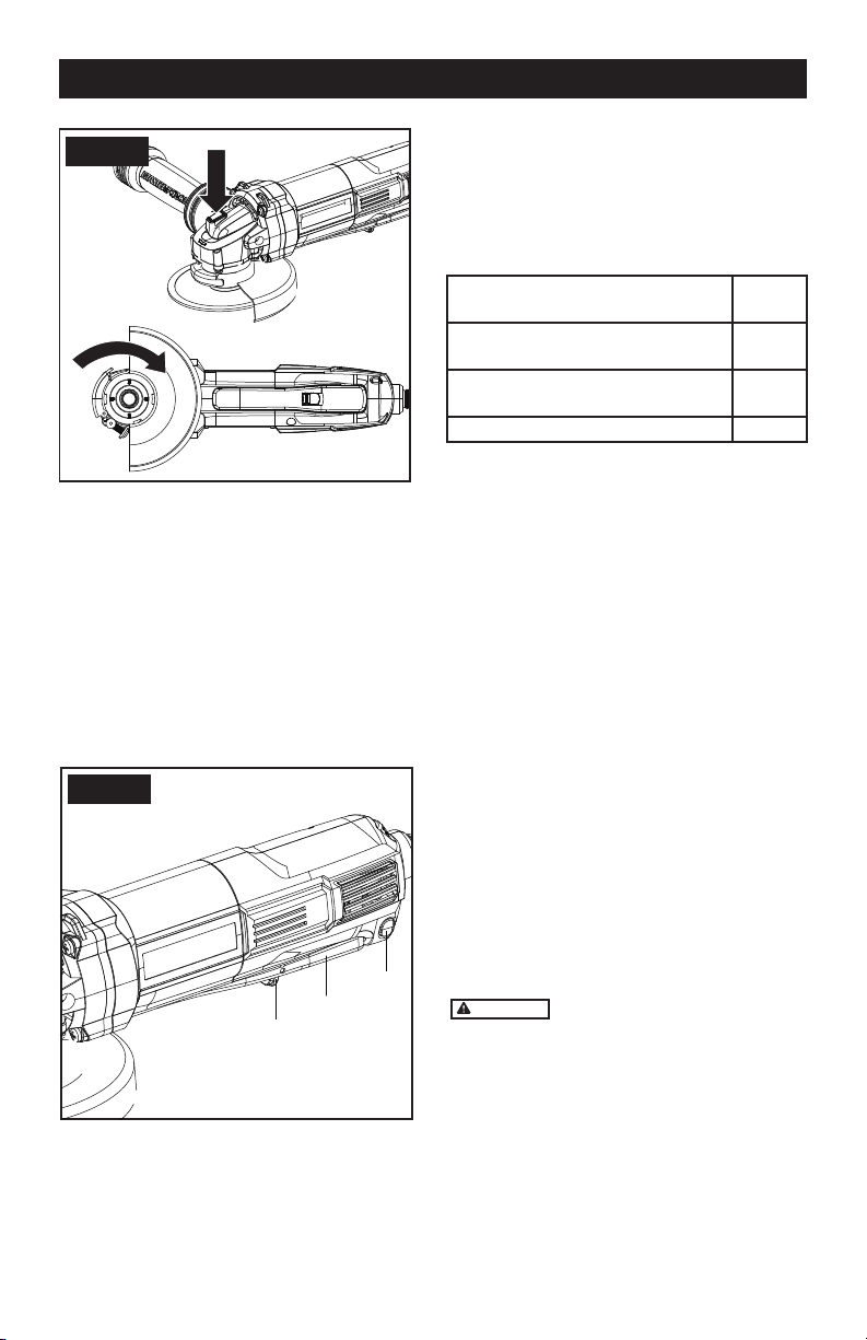
4. SAFETY ON/OFF SWITCH (SEE D)
Your switch is locked off to prevent accidental
starting. With your hand on the on/off switch (a)
use your nger to pull lever (b) forward and then
depress on/off switch (a). Then release lever (b).
Your tool is now on. To switch off just release
on/off switch.
If you want to keep the grinder running without
operation, press the lever(c) while the grinder is
running, and release on/off switch. To switch off
just press on/off switch again.
Fig. D
b
a
c
5. VARIABLE SPEED CONTROL
Adjust the thumb-wheel to increase or decrease
the speed according to the material, material
thickness and disc/accessory specication to be
used (also possible during no load operation).
See Table 1 for general guidance on speed
selection. Avoid prolonged use at very low
speeds as this may damage your angle grinder’s
motor. The Constant Speed Control electronic
circuit inside your angle grinder maintains a
nearly constant speed even when your angle
grinder is under load.
Material
Speed
setting
Grinding ferrous metals, cutting
stone, brick, etc, Wire cup brush
5-6
Grinding or sanding
non-ferrous metals, light grind-ing work
3-5
Polishing, light sanding work 1-3
6. SPINDLE LOCK BUTTON
Must only be used when changing a disc. Never
press when the disc is rotating!
7. TO USE THE GRINDER
ATTENTION: Do not switch the grinder on whilst
the disc is in contact with the workpiece. Allow the
disc to reach full speed before starting to grind.
Hold your angle grinder with one hand on the
main handle and other hand rmly around the
auxiliary handle.
Always position the guard so that as much of the
exposed disc as possible is pointing away from you.
Be prepared for a stream of sparks when the disc
touches the metal.
For best tool control, material removal and
minimum overloading, maintain an angle
between the disc and work surface of
approximately 15
0
-30
0
when grinding.
Use caution when working into corners as
contact with the intersecting surface may cause
the grinder to jump or twist.
When grinding is complete allow the workpiece
to cool. Do not touch the hot surface.
8. CUTTING
WARNING
For cutting metal, always work
with the wheel guard for cutting.
When cutting, do not press, tilt or oscillate the
machine. Work with moderate feed, adapted to
the material being cut.
Do not reduce the speed of running down cutting
discs by applying sideward pressure.
The direction in which the cutting is performed
is important.
The machine must always work in an up-grinding
motion. Therefore, never move the machine in
the other direction! Otherwise, the danger exists
of it being pushed uncontrolled out of the cut.

Page 14
Remove the plug from the socket before carrying out any adjustment, servicing or
maintenance.
Keep tools sharp and clean for better and safer performance. Follow instructions for lubricating
and changing accessories. Inspect tool cords periodically and if damaged, have repaired by
authorized service facility.
Your power tool requires no additional lubrication or maintenance. There are no user serviceable
parts in your power tool. Never use water or chemical cleaners to clean
your power tool. Wipe clean with a dry cloth. Always store your power tool in a dry place. Keep
the motor ventilation slots clean. Keep all working controls free of dust.
If the supply cord is damaged, it must be replaced by the manufacturer, its service agent or
similarly qualied persons in order to avoid a hazard.
1pc Spanner
1pc Anti-vibration auxiliary handle
1pc SDS ange
1pc 5’’ Metal grinding disc
1pc 5” Wheel guard for grinding
1pc 5” Wheel guard for cutting
We recommend that you purchase your accessories from the same store that sold you the tool. Use
good quality accessories marked with a well-known brand name. Choose the type according to the
work you intend to undertake. Refer to the accessory packaging for further details. Store personnel
can assist you and offer advice.
1.Your angle grinder is useful for both cutting through metals, i.e. for removing screw heads, and
also for cleaning / preparing surfaces, i.e. before and after welding operations.
2.Different types of wheel/cutter will allow the grinder to meet various needs. Typically, wheels/
cuttings are available for mild steel, stainless steel, stone and brick. Diamond impregnated discs
are available for very hard materials.
3. If the grinder is used on soft metals such as aluminum, the wheel will soon clog and will have
to be changed.
4. At all times, let the grinder do the work, do not force it or apply excessive pressure to the wheel/
disc.
5. If cutting a slot ensures that the cutter is kept aligned with the slot, twisting the cutter may cause
the disc to shatter. If cutting through thin sheet only allow material, excessive penetration can
increase the chance of causing damage.
6. If cutting stone or brick, it is advisable to use a dust extractor.
WORKING HINTS FOR YOUR GRINDER
TROUBLESHOOTING

Page 15
Although your new angle grinder is really very simple to operate, if you do experience problems,
please check the following:
1. If your grinder will not operate check the power at the main plug.
2. If your grinder wheel wobbles or vibrates, check that outer ange is tight, check that the wheel
is correctly located on the ange plate.
3. If there is any evidence that the wheel is damaged do not use as the damaged wheel may dis-
integrate, remove it and replace with a new wheel. Dispose of old wheels sensibly.
4. If working on aluminum or a similar soft alloy, the wheel will soon become clogged and will not
grind effectively.
5. If a fault cannot be rectied, return the tool to an authorized dealer or its service agent for repair.
TROUBLESHOOTING

Page 16
NOTES

SAVE YOUR RECEIPTS
THIS WARRANTY IS VOID WITHOUT THEM
MASTERFORCE
®
Angle Grinder
WARRANTY
90-DAY MONEY BACK GUARANTEE:
This MASTERFORCE
®
brand power tool carries our 90-DAY Money Back Guarantee.
If you are not completely satised with your MASTERFORCE
®
brand power tool for
any reason within ninety (90) days from the date of purchase, return the tool with your
original receipt to any MENARDS
®
retail store, and we will provide you a refund – no
questions asked.
3-YEAR LIMITED WARRANTY:
This MASTERFORCE
®
brand power tool carries our famous No Hassle 3-Year Limited
Warranty to the original purchaser. If, during normal use, this
MASTERFORCE
®
power tool breaks or fails due to a defect in material or workmanship
within three (3) years from the date of original purchase, simply bring this tool with the
original sales receipt back to your nearest MENARDS
®
retail store. At its discretion,
MASTERFORCE
®
agrees to have the tool or any defective part(s) repaired or replaced
with the same or similar MASTERFORCE
®
product or part free of charge, within the
stated warranty period, when returned by the original purchaser with original sales
receipt. Not withstanding the foregoing, this limited warranty does not cover
any damage that has resulted from abuse or misuse of the Merchandise.
This warranty: (1) excludes expendable parts including but not limited to blades,
brushes, belts, bits, light bulbs, and/or batteries; (2) shall be void if this tool is used
for commercial and/or rental purposes; and (3) does not cover any losses, injuries to
persons/property or costs. This warranty does give you specic legal rights and you
may have other rights, which vary from state to state. Be careful, tools are dangerous if
improperly used or maintained. Seller’s employees are not qualied to advise you on the
use of this Merchandise. Any oral representation(s) made will not be binding on seller or
its employees. The rights under this limited warranty are to the original purchaser of the
Merchandise and may not be transferred to any subsequent owner.
This limited warranty is in lieu of all warranties, expressed or implied including warranties
or merchantability and tness for a particular purpose. Seller shall not be liable for any
special, incidental, or consequential damages. The sole exclusive remedy against the
seller will be for the replacement of any defects as provided herein, as long as the seller
is willing or able to replace this product or is willing to refund the purchase price as
provided above. For insurance purposes, seller is not allowed to demonstrate any of
these power tools for you.
For questions / comments, technical assistance or repair parts
Please Call Toll Free at: 1-888-686-1484 ( (M-F 8am – 6pm)
SAV E YOUR RECEIPTS. THIS WARRANTY IS VOID WITHOUT THEM

Page 18
CUSTOMER SERVICE INFORMATION:
Now that you have purchased your tool, should a need ever exist for repair parts or service,
simply call 1-888-686-1484. Be sure to provide all pertinent facts when you call or visit.
Afilador angular
Para reducir el riesgo de lesiones, el usuario
debe leer y comprender el manual del operador. Guarde estas
instrucciones para referencia en el futuro.
Para preguntas / comentarios, asistencia técnica o partes de
reparación
Por favor llame al número telefónico gratuito al: 1-888-686-1484
(Lunes-Viernes 8am – 6pm)
241-0784

Page 20
TABLA DE CONTENIDO
Reglas de seguridad generales ....................................................21-22
Símbolos ...........................................................................................23
Declaración de uso general (aplicaciones) .........................................24
Especificacion .....................................................................................24
Eléctrico ..............................................................................................25
Características ..................................................................................26
Operación ....... .............................................................................27-29
Consejos de trabajo para su afilador angular.......................................30
Mantenga las herramientas con cuidado ...............................................30
Accesorios ............. ...........................................................................30
Solución de problemas ............. ......................................................31
Notas...................................................................................................32
Garantía ............................................................................................33

Page 21
INSTRUCCIONES DE
SEGURIDAD
El polvo originado por
la utilización de herramientas motorizadas
contiene químicos que, según el Estado
de California, causan cáncer, defectos
congénitos y otros daños reproductivos.
Algunos ejemplos de esos productos
químicos son:
● El plomo de las pinturas a base de plomo
● La sílice cristalina de los ladrillos, del
cemento y de otros productos de albañilería
● El arsénico y el cromo de la madera
tratada químicamente
El riesgo que se corre a causa del contacto
con esos productos varía según la frecuencia
con que usted realice este tipo de trabajos.
Con el n de reducir su exposición a esas
substancias químicas, trabaje en un área
bien ventilada; utilice un equipo de seguridad
adecuado, tal como una máscara contra el
polvo especialmente diseñada para ltrar
partículas microscópicas.
Este producto puede
exponerlo a químicos que incluyen plomo,
ftalato, o bisfenol A que se sabe en el Estado
de California que causan cáncer, defectos
de nacimiento u otros daños reproductivos.
Lave sus manos después de usarlo. Para
más información visite www.P65Warnings.
ca.gov.
Advertencias De Seguridad
Generales Para La Herramienta
Motorizada
Lea y comprenda todas
las instrucciones. El no seguir todas
las instrucciones a continuación puede
ocasionar descargas eléctricas, incendios
y/o heridas graves.
Conserve todas las advertencias e
instrucciones para consulta futura.
El término “herramienta eléctrica” que gura
en todas las advertencias que aparecen a
continuación hace referencia a la herramienta
que funciona con la red de suministro
eléctrico (con cable) o a la herramienta
eléctrica accionada a baterías (sin cable).
ÁREA DE TRABAJO
• Mantenga su lugar de trabajo limpio
y bien iluminado. Bancos de trabajo
desordenados y lugares oscuros invitan a los
accidentes.
• No utilice herramientas eléctricas en
atmósferas explosivas, como por ejemplo
en presencia de líquidos, inflamables,
gases o polvo. Las herramientas eléctricas
crean chispas que pueden encender el polvo
o los vapores.
• Mantenga a los espectadores, niños
y visitantes a una distancia prudente
cuando esté utilizando una herramienta
eléctrica. Las distracciones pueden hacerle
perder el control.
SEGURIDAD ELÉCTRICA
• Los enchufes de las herramientas
eléctricas deben coincidir con el
tomacorriente. No modifique de algún
modo el enchufe. No utilice enchufes
adaptadores con herramientas eléctricas
conectadas a tierra. Si no se modican los
enchufes y se utilizan los tomacorrientes
adecuados, se reducirá el riesgo de una
descarga eléctrica.
• Evite el contacto del cuerpo con las
superficies conectadas a tierra tales como
tuberías, radiadores, estufas de cocina
y refrigeradores. Existe mayor riesgo de
que se produzcan descargas eléctricas si su
cuerpo está conectado a tierra.
• No exponga las herramientas
eléctricas a la lluvia ni a los ambientes
húmedos. La entrada de agua en una
herramienta eléctrica aumenta el riesgo de
que se produzcan descargas eléctricas.
• No abuse del cable. Nunca use el cable
para transportar las herramientas ni para
sacar el enchufe de un tomacorriente.
Mantenga el cable alejado del calor, el aceite,
los bordes alados o las piezas móviles. Los
cables dañados aumentan el riesgo de que
se produzcan descargas eléctricas.
• Cuando opere una herramienta
eléctrica en exteriores, use un cable
de extensión adecuado para uso en
exteriores. El uso de un cable adecuado
para uso en exteriores reduce el riesgo de
descargas eléctricas.
• Si operar una herramienta eléctrica en
un lugar húmedo es inevitable, use
REGLAS DE SEGURIDAD GENERALESs

Page 22
GENERAL SAFETY RULE
un elemento protegido del dispositivo de
corriente residual (RCD). El uso de un RCD
reduce el riesgo de descargas eléctricas.
SEGURIDAD PERSONAL
• Manténgase alerta, fíjese en lo que
está haciendo y use el sentido común
cuando utilice una herramienta eléctrica.
No use la herramienta cuando esté cansado
o se encuentre bajo la inuencia de drogas,
alcohol o medicamentos. Un momento de
distracción al utilizar herramientas eléctricas
puede dar lugar a lesiones personales graves.
• Utilice equipo de seguridad. Use
siempre protección ocular. La utilización del
equipo de seguridad como mascara antipolvo,
zapatos de seguridad antideslizantaes,
casco o protección auditiva para condiciones
adecuadas reducirá el riego de lesiones
personales.
• Evite el arranque accidental. Asegúrese
de que el interruptor esté en la posición
de trabado o de apagado antes de instalar
el paquete de baterías. Transportar
herramientas con el dedo en el interruptor
o instalar el paquete de batería cuando
el interruptor está encendido invitan a los
accidentes.
• Retire las llaves o claves de ajuste antes
de encender la herramienta. Una llave o
clave de ajuste dejada en una parte giratoria
de la herramienta puede causar una lesión
personal.
• No intente alcanzar demasiado lejos.
Mantenga un apoyo de los pies y un
equilibrio adecuados en todo momento.
El apoyo de los pies y el equilibrio adecuados
permiten un mejor control de la herramienta
en situaciones inesperadas.
• Vístase apropiadamente. No se ponga
ropa holgada ni joyas. Mantenga su
cabello, ropa y guantes alejados de las
piezas móviles. La ropa holgada, las joyas o
el pelo largo pueden quedar atrapados en las
piezas móviles.
• Si se proporcionan dispositivos para
la extracción y recolección de polvo,
asegúrese que estos estén conectados
y utilizados correctamente. El uso de
estos dispositivos puede reducir peligros
relacionados con el polvo.
USO Y CUIDADO DE LA HERRAMIENTA
• No fuerce la herramienta. Emplee la
herramienta correcta para la aplicación
que desea. La herramienta correcta hará
el trabajo mejor y con más seguridad a la
capacidad nominal para la que está diseñada.
• No utilice la herramienta si el interruptor
no la enciende o apaga. Toda herramienta
que no se pueda controlar con el interruptor
es peligrosa y debe ser reparada.
• Desconecte la batería de la herramienta
o ponga el interruptor en la posición de
trabado o de apagado antes de hacer
cualquier ajuste, cambio de accesorios o
guardar la herramienta. Estas medidas de
seguridad preventivas reducen el riesgo de
encender la herramienta accidentalmente.
• Guarde las herramientas que no esté
usando fuera del alcance de los niños
y otras personas no capacitadas. Las
herramientas son peligrosas en las manos de
los usuarios no capacitados.
• Mantenga las herramientas con
cuidado. Compruebe la desalineación o
el atasco de las piezas móviles, la ruptura
de piezas y cualquier otra situación que
pueda afectar el funcionamiento de las
herramientas. Si la herramienta está dañada,
hágala arreglar antes de usarla. Muchos
accidentes son causados por herramientas
mantenidas decientemente.
• Conserve las herramientas de corte
afiladas y limpias. Las herramientas
mantenidas adecuadamente, con bordes de
corte alados, tienen menos probabilidades
de atascarse y son más fáciles de controlar.
• Utilice la herramienta eléctrica,
accesorios, brocas de la herramienta,
etc. de acuerdo con estas instrucciones
y de la manera adecuada para el tipo de
herramienta eléctrica, teniendo en cuenta
las condiciones de trabajo y el trabajo que
se realizará. La utilización de la herramienta
eléctrica para operaciones diferentes de
aquellas para las que se encuentra diseñada
podría dar lugar a una situación peligrosa.
5. REPARACIÓN
• La herramienta debe ser reparada por
una persona calificada de servicio técnico
y se deben utilizar partes de reemplazo
idénticas. Esto asegurará el mantenimiento
de la seguridad de la herramienta eléctrica.

Page 23
IMPORTANTE: Su herramienta eléctrica y su Instructivo puede contener “ICONOS DE
ADVERTENCIA” (un símbolo en imagen que le advierte, y/o le indica cómo evitar un condición
potencialmente peligrosa). Entender y apegarse a estos símbolos le ayudará a operar su
herramienta mejor y de manera más segura. A continuación se muestran algunos de los símbolos
que puede ver.
CONSERVE ESTAS INSTRUCCIONES
Para reducir el riesgo de lesiones, el usuario deberá leer el manual de instrucciones
Use lentes de seguridad
Use máscara contra el polvo
Use protección auditiva
Doble aislamiento
SÍMBOLOS
Page 24
No intente usar este producto hasta que lea minuciosamente y entienda por completo
el instructivo. Ponga mucha atención a las reglas de seguridad, incluyendo peligro,
Advertencias, y Precauciones.
La operación de cualquier herramienta puede resultar en que objetos extraños sean
arrojados hacia susojos, lo que puede resultar en daño severo a los ojos. Antes de co-
menzar cualquier operación, siempre use gafas o lentes de seguridad con protectores
laterales y una careta completa cuando sea necesario. Recomendamos la Máscara
de seguridad de visión amplia para uso sobre sus lentes o gafas de seguridad están-
dar con protectores laterales. Siempre use protección para los ojos que cumpla con
ANSI Z87.1.
DECLARACIÓN DE USO GENERAL (APLICACIONES)
Sku: 241-0784
Voltios 120V~60Hz
Entrada de energía nominal 10A
Ajuste de control de velocidad 5500-11000/min
Espesor de ruedas de pulido 5.5mm
Diámetro de ruedas de pulido 125mm
Dimensiones críticas
Diámetro del disco 5"(125mm)
Oricio del disco 7/8"(22.2mm)
Rosca de eje 5/8"-11
Peso de la máquina 5.06lbs (2.3kg)
Doble aislamiento
/II

Page 25
DOBLE AISLAMIENTO
El doble aislamiento es un concepto de seguridad para herramientas eléctricas,
que elimina la necesidad del cable eléctrico con tierra de tres alambres habitual.
Todas las partes de metal expuestas están aisladas de los componentes de metal
internos del motor con aislamiento de protección.
Las tierras con doble aislamiento no necesitan conectarse a tierra.
El sistema de doble aislamiento está diseñado para proteger al usuario contra
choque que resulte de una ruptura en el cableado interno de la herramienta. Observe todas las pre-
cauciones normales de seguridad para evitar el choque eléctrico.
IMPORTANTE: Dar servicio a una herramienta con doble aislamiento requiere cuidado
extremo y conocimiento del sistema y sólo debe ser realizado por un técnico de servicio
calicado. Siempre use las partes de reemplazo de fábrica originales cuando dé servicio.
CONEXIÓN ELÉCTRICA
La Pulidora de Ángulo tiene un motor eléctrico integrado de precisión. Se debe conectar a un sumi-
nistro de energía que tenga 120 voltios, 60 Hz, sólo CA (corriente doméstica normal). No opere esta
herramienta en corriente directa (CD). Una caída de voltaje substancial causará una pérdida de en-
ergía y el motor se sobrecalentará. Si su herramienta no opera cuando esté conectada a un enchufe,
revise de nuevo el suministro de energía.
USE EL CABLE DE EXTENSIÓN ADECUADO. Asegúrese que su cable de extensión esté en
buenas condiciones. Cuando use un cable de extensión, asegúrese usar uno lo sucientemente
fuerte para manejar la corriente que requerirá su producto. Un cable de menor capacidad causará
una caída en el voltaje de línea que resulte en una pérdida de energía y sobrecalentamiento. La Tabla
1 muestra el tamaño correcto a usar dependiendo de la longitud del cable y la capacidad de amperes
de la placa de identicación. Si tiene dudas, use el siguiente calibre mayor. Mientras menor es el
número de calibre, el cable es más pesado.
Las palabras en la imagen también se deben traducir, 16 palabras en total.
Rating Voltios Longitud total de la cuerda en pies
Amperaje 120V 25ft. 50ft. 100 ft. 150 ft.
Más de No más de AWG
0
6
10
6
10
12
18
18
16
16
16
16
16
14
14
14
12
12
12 16 14 12 No se recomienda
Mantenga el cable de extensión libre del área de trabajo. Coloque el cable de forma
que no quede atrapado sobre madera, herramientas u otras obstrucciones mientras esta trabajando
con una herramienta eléctrica.
Revise los cables de extensión antes de cada uso. Si están dañados reemplácelos de
inmediato. Nunca use una herramienta con un cable dañado ya que tocar el área dañada podría causar
choque eléctrico que resulte en lesiones serias
ELÉCTRICO

Page 26
CONOZCA SU PULIDORA DE NGULO
Antes de intentar usar cualquier herramienta, familiarícese con todas las características de
operación y los requerimientos de seguridad.
CARACTERÍSTICAS
1. Áreas de agarre
2. Mango auxiliar anti-vibración
3. Botón de bloqueo del eje
4. Discos
5. Protección de rueda para pulido
6. llave
7. Reborde interior
8. Reborde exterior
9. Tuerca de ajuste de la abrazadera
10. Eje
11. Palanca de jación de la cubierta protectora
12. Gatillo de encendido/apagado
13. Control de velocidad variable
14. Protección de rueda para corte *
15. Botón de bloqueo de encendido
16. Brida SDS
1 12 13
15
5
4
14
2
3
8 76 16
9
10
11
Page 27
INSTRUCCIONES DE USO
NOTA: Antes de usar la herramienta, lea
atentamente el manual de instrucciones.
Esta herramienta puede causar síndrome
de vibración de mano-brazo si su uso no se
administra adecuadamente.
1. INSTALACIÓN DE MANIJA AUXILIAR
(VER FIG. A1, A2)
Tiene 2 posiciones de trabajo que permiten
mayor comodidad y mejor control del alador
angular. El mango se enrosca en el sentido de
las agujas de un reloj en cualquier agujero de
los costados de la caja de engranajes.
Mango auxiliar de prevención de vibración
El mango auxiliar de prevención de vibración
reduce las vibraciones, haciendo la operación
más confortable y segura. Su herramienta está
equipada con una manija auxiliar que se puede
usar para almacenamiento de la llave. (Ver Fig. A2)
Fig. A1
Fig. A2
2. INSTALACIÓN Y AJUSTE DE
PROTECCIÓN DE DISCO
Antes de trabajar con la máquina, desconecte
el cable de alimentación.
Para trabajar con discos de amoladura o corte
debe estar montada la cubierta protectora.
La proyección codicada de la cubierta
protectora garantiza que sólo pueda montarse
la protección adecuada para el tipo de
máquina. Levante la palanca de sujeción de la
protección (Ver Fig. B1).
Para instalar la protección alinee la proyección
de la protección con la ranura de empate sobre
el alojamiento del husillo (Ver Fig. B1). Empuje
la protección hacia abajo tanto como se pueda.
Gire la protección a una posición de operación
(Ver Fig. B2 ejemplo).
NOTA: La posición de operación es con el lado
cerrado de la protección hacia el operador y el
lado abierto apuntando directamente al lado
opuesto del operador para proporcionar la
protección máxima contra chispas y desechos
expulsados.
Cierre la palanca de sujeción para apretar (Ver
Fig. B3 ejemplo).
Fig. B1
Abra la palanca de sujeción de la protección
Inserte y gire en sentido
de las manecillas del reloj
Proyección
INSTRUCCIONES DE FUNCIONAMIENTO
Page 28
Fig. B2
Posición de operación (ejemplo)
Abra la palanca de sujeción de la protección
Fig. B3
Posición de operación (ejemplo)
Palanca de sujeción de protección cerrada
3. MONTAJE DEL DISCO (VER FIG. C1, C2)
Coloque la brida sobre el husillo de la
herramienta. Asegúrese que esté ubicada
sobre los dos planos del husillo.
Coloque el disco sobre el husillo de la
herramienta y la brida interior. Asegúrese
que esté ubicado correctamente. Instale la
brida exterior roscada asegurándose que vea
en la dirección correcta para el tipo de disco
instalado. Para discos de pulido, la brida se
instala con la porción elevada viendo hacia el
frente del disco. Para discos de corte, la brida
se instala con la porción elevada viendo al lado
opuesto del disco (Ver Fig. C1).
Presione el botón de bloqueo del husillo y
gire el husillo a mano hasta que se bloquee.
Manteniendo el botón de bloqueo presionado,
apriete la brida exterior con la llave incluida.
(Ver Fig. C2). Para la brida SDS, mantenga el
botón de bloqueo presionado y apriete la brida
SDS con la mano. (Ver Fig. C3)
Fig. C1
Fig. C2
Fig. C3
OPERACIÓN
Page 29
OPERACIÓN
4. INTERRUPTOR DE SEGURIDAD DE
ENCENDIDO/APAGADO (VER FIG. D)
El gatillo se encuentra bloqueado para prevenir el
arranque accidental. Apoye su mano en el gatillo (a),
use un dedo para deslizar la palanca (b) hacia delante
y luego presione el gatillo (a) (Ver Fig. A). Luego
suelte la palanca (b). Su herramienta está encendida.
Para apagarla, simplemente suelte el gatillo.
Si desea mantener la amoladora encendida sin
operación, presione la palanca (c) mientras la
amoladora está operando, y libere el interruptor de
encendido/apagado. Para apagar sólo presione el
interruptor de encendido/apagado de nuevo.
Fig. D
b
a
c
5. CONTROL DE VELOCIDAD VARIABLE
Ajustar la rueda para aumentar o reducir la
velocidad según el material, su espesor y las
especicaciones del disco/accesorio utilizado
(también es posible durante la operación
sin carga). Ver el cuadro 1 para una ayuda
general en la elección de la velocidad. Evitar
cualquiera utilización prolongada a baja
velocidad porque eso podría dañar el motor de
del alador angular. El circuito electrónico de
control de velocidad constante en el interior del
alador angular proporciona una velocidad casi
constante aun con el alador bajo carga.
Material
Ajuste de
velocidad
Afilar metales ferrosos, cortar
piedra, ladrillo, etc., cepillado
de alambre
5-6
Afilar o lijar metales no
ferrosos, pequeños trabajos
de amolado
3-5
Pulir, pequeños trabajos de
lijado
1-3
6. BOTÓN DE BLOQUEO DEL EJE
Debe utilizarse únicamente durante el cambio
del disco. Nunca apretar cuando el disco gira.
7. PARA USAR EL AFILADOR
ATENCIÓN: No encienda el afilador cuando
el disco esté en contacto con la pieza
de trabajo. Deje que el disco alcance la
velocidad máxima antes de empezar a
trabajar.
Sostenga su alador con una mano en el
mango principal y la otra mano rmemente en el
mango auxiliar.
Coloque siempre la cubierta de modo que la
mayor parte posible del disco expuesto no
quede apuntando hacia usted.
Esté preparado para una ráfaga de chispas
cuando el disco toque el metal.
Para controlar mejor la herramienta, sacar
material y minimizar la sobrecarga, mantenga
un ángulo de unos 15
o
-30
o
entre el disco.
Presione levemente el disco abrasivo para
una operación más eciente. El presionar
demasiado causará que baje la velocidad y
puede causarle sobrecarga y daños al motor.
Tenga cuidado al trabajar las puntas ya que el
contacto con la supercie del otro lado puede
hacer que el alador salte o se tuerza. Una vez
que termine, deje que la pieza de trabajo se
enfríe. No toque las supercies calientes.
8. CORTE
Para cortar metal, siempre
trabaje con la protección de la rueda para corte.
No presione, incline ni balancee la máquina
mientras corta. Trabaje a una velocidad
moderada, adaptada al material a cortar.
No reduzca la velocidad del disco de corte
aplicando presión desde los laterales.
La dirección en la que se realiza el corte es
importante.
La máquina debe utilizarse realizado
movimientos ascendentes. ¡No mueva la
máquina en la otra dirección! De lo contrario
podría salir despedida sin control durante el
corte.

Page 30
Estos accesorios o suplementos se recomiendan para uso con su Multi-herramienta especicada
en este manual. El uso de cualquier otro accesorio o suplemento podría presentar un riesgo de
lesiones a las personas. Sólo use el accesorio o suplemento para su propósito indicado.
1 llave
1 Mango auxiliar anti-vibración
1 Brida SDS
1 5’’ Disco de pulido de metal
1 5” Protección de rueda para pulido
1 5” Protección de rueda para corte
Extraiga el enchufe de la toma eléctrica antes de llevar a cabo cualquier reparación o
ajuste.
Conserve las herramientas aladas y limpias para que funcionen mejor y con más seguridad.
Siga las instrucciones para lubricar y cambiar los accesorios. Inspeccione periódicamente
los cables de las herramientas y si están dañados hágalos reparar por un centro de servicio
autorizado.
Su herramienta no requiere lubricación ni mantenimiento adicional. No posee piezas en su
interior que puedan ser reparadas por el usuario. Nunca emplee agua o productos químicos
para limpiar su herramienta. Use simplemente un paño seco. Guarde siempre su herramienta
en un lugar seco. Mantenga limpias las ranuras de ventilación del motor. Mantenga todos los
controles de operación libres de polvo.
Si el cable de alimentación se encuentra dañado deberá ser reemplazado por el fabricante,
su agente de servicio o algún otro profesional igualmente cualicado para llevar a cabo dichas
operaciones, con el n de evitar riesgos.
1. El alador angular es útil para cortar metales, por ejemplo, para extraer cabezas de tornillos y
para limpiar/preparar supercies, por ejemplo, antes y después de las operaciones de soldadura.
2. Los diferentes tipos de ruedas/herramientas de corte permitirán que el alador posea varias
funciones. Generalmente, las ruedas/herramientas de corte están disponibles para hierro lamina-
do, acero inoxidable, piedra y ladrillo. También se encuentran disponibles los discos impregnados
de diamante para materiales sumamente duros.
3. Si se utilizará el alador en materiales blandos como aluminio, la rueda se atascará y deberá
ser reemplazada.
4. Permita siempre que la herramienta haga el trabajo. No fuerce la herramienta ni aplique una
presión excesiva a la rueda/disco.
5 Si está realizando el corte de un oricio, asegúrese de que la herramienta de corte quede
alineada con el oricio. Torcer la herramienta podría causar daños al disco. Si está realizando
un corte a través de una lámina de poco grosor, sólo permita que una pequeña parte de la hoja
ingrese en el material. Una penetración excesiva puede aumentar las posibilidades de causar
daños.
6. Si está realizando el corte de una piedra o ladrillo, se recomienda utilizar un extractor de polvo.
CONSEJOS DE TRABAJO PARA SU AFILADOR ANGULAR
MANTENGA LAS HERRAMIENTAS CON CUIDADO
ACCESORIOS

Page 31
A pesar de que el alador angular nuevo es realmente muy simple de utilizar, si posee algún
problema, consulte los puntos que aparecen a continuación:
1. Si el alador no funciona, compruebe la alimentación en el tomacorriente.
2. Si la rueda del alador se tambalea o vibra, compruebe que el reborde exterior esté colocado
de forma segura. Compruebe que la rueda esté colocada de forma correcta sobre el reborde.
3. Si existe algún indicio de que la rueda está dañada, no la utilice, debido a que una rueda
dañada podría desintegrarse. Retírela y reemplácela por una rueda nueva. Deseche las ruedas
usadas de forma razonable.
4. Si está trabajando en aluminio o en otra aleación liviana similar, la rueda quedará atorada y no
alará de forma ecaz.
5. Si no se puede solucionar una falla, regrese la herramienta a un distribuidor autorizado o a su
agente de servicio técnico para efectuar la reparación.
SOLUCIÓN DE PROBLEMAS

Page 32
NOTAS

Page 33
GARANTÍA DE Pulidora de Ángulo MASTERFORCE
®
GARANTÍA DE DEVOLUCIÓN DE DINERO DE 90 DÍAS:
Esta herramienta eléctrica de la marca MASTERFORCE
®
tiene nuestra Garantía de
devolución de dinero de 90 DÍAS. Si no está completamente satisfecho con su herramienta
eléctrica marca MASTERFORCE
®
por cualquier razón dentro de noventa (90) días desde
la fecha de compra, regrese la herramienta con su recibo original a cualquier tienda al
menudeo MENARDS
®
, y le proporcionaremos un reembolso – sin hacer ninguna pregunta.
GARANTÍA LIMITADA DE 3 AÑOS:
Esta herramienta eléctrica marca MASTERFORCE
®
tiene nuestra famosa Garantía Limitada
de 3 Años sin Complicaciones para el comprador original. Si, durante el uso normal, esta
herramienta eléctrica MASTERFORCE
®
se descompone o falla debido a un defecto en
material o mano de obra dentro de tres (3) años desde la fecha de la compra original,
simplemente lleve esta herramienta con el recibo de ventas original de regreso a su
tienda al menudeo MENARDS
®
más cercana. A su criterio, MASTERFORCE
®
acuerda
que la herramienta o cualquier parte defectuosa se repare o reemplace con el mismo
producto o parte MASTERFORCE
®
o similar libre de cargo, dentro del periodo de
garantía mencionado, cuando sea devuelta por el comprador original con el recibo de
ventas original. Sin importar lo presente, esta garantía limitada no cubre ningún daño
que haya resultado a partir de abuso o mal uso de la Mercancía.
Esta garantía: (1) excluye partes desechables que incluyen, sin limitarse a aspas, cepillos,
bandas brocas, focos, y/o baterías; (2) se anulará si esta herramienta se usa para
propósitos comerciales y/o de renta; y (3) no cubre ninguna pérdida, lesiones a personas/
daño a la propiedad o costos. Esta garantía le otorga derechos legales especícos y puede
tener otros derechos, que varían de un estado a otro. Tenga cuidado, las herramientas
son peligrosas si se usan incorrectamente o se les da mantenimiento inadecuado. Los
empleados del vendedor no están calicados para aconsejarlo sobre el uso de esta
Mercancía. Cualquier representación verbal realizada no será vinculante para el vendedor
o sus empleados Los derechos bajo esta garantía limitada son para el comprador original
de la Mercancía y no se pueden transferir a ningún propietario subsecuente.
Esta garantía limitada está en lugar de todas las garantías, expresas o implícitas
incluyendo garantías o comerciabilidad o adecuación para un propósito particular.
El vendedor no será responsable por cualquier daño especial, incidental o en
consecuencia. El único remedio exclusivo contra el vendedor será el reemplazo de
cualquier defecto como se indica en el presente, siempre y cuando el vendedor desee
o pueda reemplazar este producto o desee reembolsar el precio de compra como
se indica anteriormente. Para propósitos de seguro, no se permite que el vendedor
demuestre ninguna de estas herramientas eléctricas para usted.
Para preguntas / comentarios, asistencia técnica o partes de reparación
Por favor llame al número telefónico gratuito al: 1-888-686-1484 ( (Lunes-Viernes 8am – 6pm)
CONSERVE SUS RECIBOS. ESTA GARANTÍA
ES NULA SIN ELLOS