Loading ...
Loading ...
Loading ...
7
INSTALLATION INSTRUCTIONS
Prepare Location
■ It is recommended that the vent system be installed
beforehood is installed.
■ Before making cutouts, make sure there is proper
clearancewithin the ceiling or wall for exhaust vent.
■ Check your ceiling height and the hood height
maximumbefore you select your hood.
1. Disconnect power.
2. Determine which venting method to use: roof, wall,
or non-vented.
3. Select a at surface for assembling the range hood.
Placecovering over that surface.
4. Using two or more people, lift range hood onto
coveredsurface.
5. Remove wood base from range hood and dispose
ofproperly.
6. Remove the metal grease lter and the white foam shipping
block from inside the range hood located below theblower.
Range Hood Mounting Screws Installation
1. Determine and mark the centerline on the wall where
thecanopy hood will be installed.
2. Select a mounting height between a minimum of 24" (61cm)
for an electric cooking surface, a minimum of 27" (68.6 cm)
for a gas cooking surface, and a suggested maximum of
36"(91.4 cm) above the range to the bottom ofthe hood.
Mark a reference line on the wall.
3. Tape template in place, aligning the template centerline
andbottom of template with hood bottom line and with
thecenterline marked on the wall..
A. Centerline
B. Fastener locations
C. Mounting height reference (hood bottom line)
DRILL 2 (TWO)
3
/
16
˝ (4.8 mm) PILOT HOLES THROUGH STUDS OR REAR WALL SUPPORTS
PERCER DEUX (2) AVANT-TROUS DE
3
/
16
˝ (4.8 mm) DANS LES
MONTANS OU LES SUPPORTS DU MUR ARRIÈRE
HAGA 2 ORIFICIOS DE
3
/
16
˝ (4.8 mm) SOBRE LOS SOPORTES DE LA PARED TRASERA
REAR WALL
MOUNTING TEMPLATE
GABARIT DE MONTAGE
DU MUR ARRIERE
PARED POSTERIOR
PLANTILLA DE MONTAJE
ALIGN BOTTOM EDGE WITH PENCIL LINE INDICATING
BOTTOM OF THE HOOD
ALIGNER LA LIGNE HORIZONTALE AVEC LA LIGNE DE
CRAYON INDIQUANT LA PARTIE INFÉRIEURE DE LA HOTTE
ALINEE LA LÍNEA HORIZONTAL CON LA LÍNEA DE LÁPIZ QUE
INDICA LA PARTE INFERIOR DE LA CAMPANA
HORIZONTAL LINE
LIGNE HORIZONTALE
LINEA HORIZONTAL
INSTALLATION HEIGHT
HAUTEUR DE L’INSTALLATION
ALTURA DE INSTALACIÓN
VERTICAL CENTERLINE
AXE CENTRAL VERTICAL
LÍNEA CENTRAL VERTICAL
DM09DC
NOTE: TEMPLATE MAY NOT BE TO SCALE.
MEASURE ALL DIMENSIONS.
REMARQUE: LE MODÈLE NE POURRAIT PAS ÊTRE
EN ÉCHELLE. MESUREZ TOUTES LES DIMENSIONS.
NOTA: LA PLANTILLA PUEDE NO ESTAR A ESCALA
REAL. EFECTUE TODAS LAS MEDICIONES.
10˝ (254 mm)
11˝ (280 mm)
A
B
C
4. Mark centers of the fastener locations through the template
to the wall.
IMPORTANT: All canopy mounting screws must be installed
into wood where possible. If there is no wood to screw into,
additional wall framing supports may be required or use(4)
10 x 60 mm wall anchors and 5.4 x 75 mm screws (not
included).
Remove the template.
5. For wood, drill
3
/
16
" (4.8 mm) pilot holes at all locations
wherescrews are being installed into wood.
For wall anchors, drill
7
/
16
" (10 mm) holes at all locations
where wall anchors are being used.
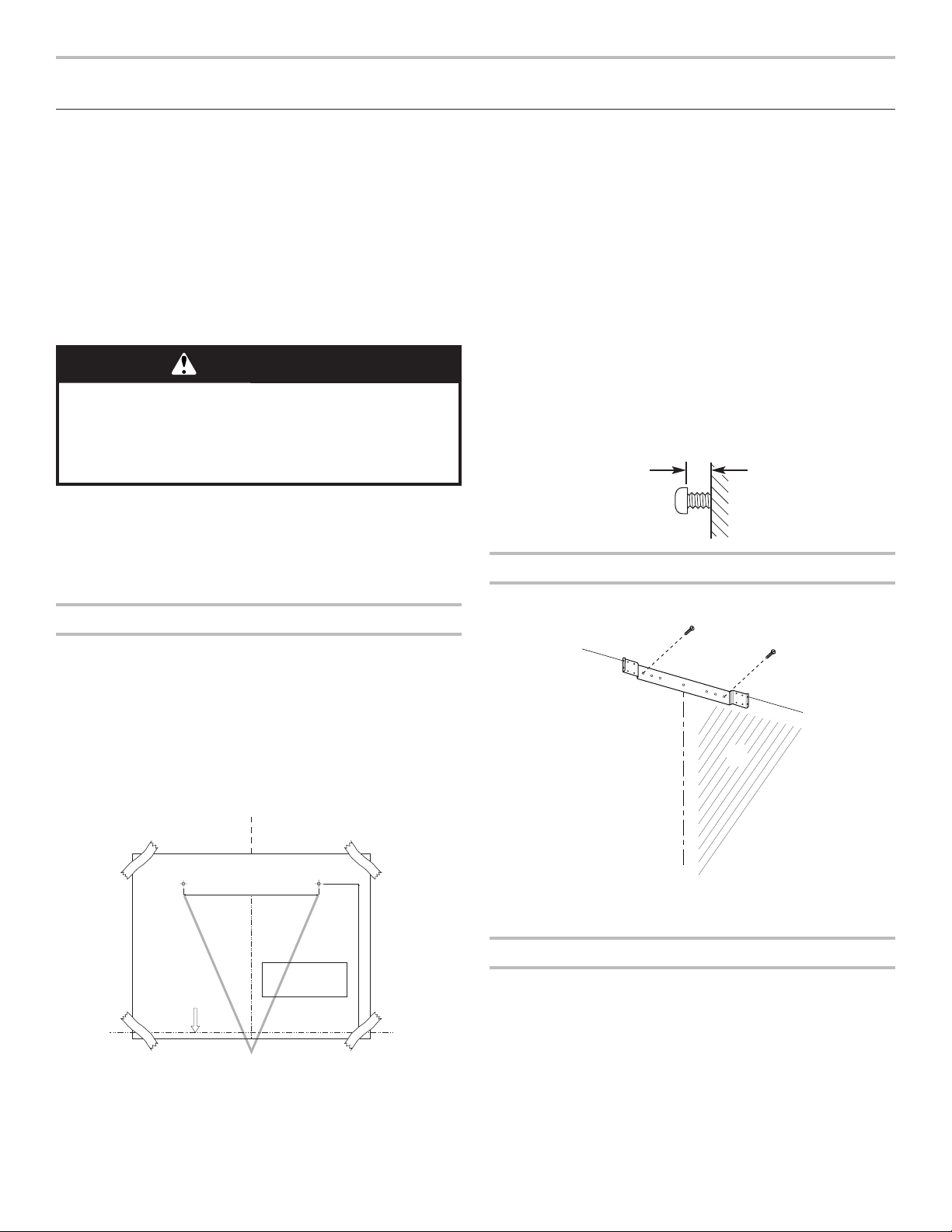
6. For wood, install (2) 5 x 45 mm mounting screws. Leave
a
1
/
4
" (6.4 mm) gap between the wall and the back of the
screw head to slide range hood into place.
For wall anchors, install the 10 x 60 mm wall anchors
andinstall the 5.4 x 75 mm screws into the wall anchors.
Tighten until the wall anchors are secure. Back the screws
out
1
/
4
" (6.4 mm).
Vent Cover Bracket Installation
1. Attach vent cover bracket to wall ush to the ceiling using (2)
5 x 45 mm screws. Use the optional wall anchors if needed.
Complete Preparation (Vented only)
1. Determine and make all necessary cuts in the wall for the
vent system. Install the vent system before installing the
hood. See “Venting Requirements” section.
2. Determine the required height for the home power supply
cable and drill a 1
1
/
4
" (3.2 cm) hole at this location.
3. Run the home power supply cable according to the National
Electrical Code or CSA Standards and local codes and
ordinances. There must be enough
1
/
2
" (12.7 mm) conduit
and wires from the fused disconnect (or circuit breaker) box
to make the connection in the hood’s electrical terminal box.
NOTE: Do not reconnect power until installation is complete.
4. Use caulk to seal all openings.
WARNING
Excessive Weight Hazard
Use two or more people to move and install
range hood.
Failure to do so can result in back or other injury.
¹⁄₄"
(6.4 mm)
A
C
B
A. Ceiling
B. Wall
C. Centerline
Loading ...
Loading ...
Loading ...