Loading ...
Loading ...
Loading ...
BTH ULTRA Electric Boilers Installation & Operation manual (Revision: June 2015) 14
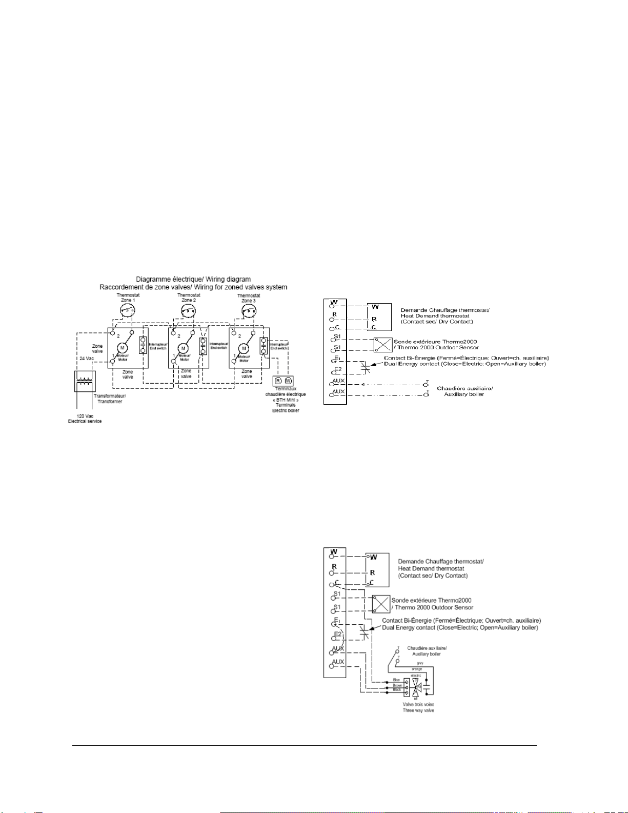
Zoning applications with motorized valves
Connect the end switch contact of all motorized
valve to terminals R & W on the boiler.
Connect the circulator to terminals “P” and “P”- in
the boiler.
The connection of the thermostats to their
corresponding zone valve shall be done according
to the zone valve manufacturer’s instructions. See
on fig.5 below a typical example.
The R & C terminals on the boiler can be used to
supply 24Vac to the zone valves if the
corresponding load does not exceed 15VA.
Otherwise an external transformer will be required.
Voltage at the outlet of the transformer shall never
be under 24Vac.
Figure 10 : Zoning with motorized valves
3.5.4 Dual-energy connection with an
auxiliary boiler.
The BTH ULTRA boiler is designed to enable the
installation on Dual-energy applications without
the need to install an interface controller between
the boilers and the electricity supplier authorization
signal. Upon the reception of that signal (dry
contact), the BTH ULTRA will select the
appropriate heating mode and will activate the
required boiler.
If the heating distribution system is equipped with
only one pump connected to the P P terminals of
the boiler, it will be activated on heat calls from the
thermostat no matter the heating mode selected.
To allow the operation in dal-energy:
o Open the front access panel to the boiler
electric compartment. Remove the screw at
the bottom of the controller, raise the upper
section of the controller. You will see a switch
at the back of the controller having two
positions “ELECT” and “Bi-Energ”. Position the
switch at “Bi-Energ”
o Install a 2 wire 18ga cable between the
contact (N/F close contact to allow the
operation in electricity, Red R wire and green
V wire of Hydro-Quebec) of the external
device making the selection of the operating
mode and terminals E1E2
o If the piping installation is made as shown
on fig.7 without a three way valve:
Install an 18ga two wire cable between boiler
terminals “AUX” and the TT terminals of the
auxiliary boiler. The capacity of the AUX
contact is 2A/24Vac max.
o Do not connect the main electrical supply
of the auxiliary boiler to AUX terminals
o The auxiliary boiler target temperature will not
be controlled by the electric boiler. It has to be
controlled by its own operating and limit
controller.
o See the operating sequence in Dual-energy at
section 4.11.
Figure 11 Connexions without three way valve
If the installation is made as shown on fig.8
then with a three way valve (in Option): Install a
three wire 18ga cable between the valve and the
electric boiler terminals. Following this, connect
the end switch of the valve (grey and orange wire)
to the T T terminals of the auxiliary boiler.The
auxiliary boiler target temperature will not be
controlled by the electric boiler. It has to be
controlled by its own operating and limit controller.
Figure 12 : Connexions with three way valve
Loading ...
Loading ...
Loading ...