Loading ...
Loading ...
Loading ...
BTH ULTRA Electric Boilers Installation & Operation manual (Revision: June 2015) 12
3.4.10 Dual Energy piping
Piping connections between the two boilers can be
made in parallel or in series as illustrated in fig.
7&8.
When installed in parallel, a three way motorized
valve (1”NPTF) is used to guide the heating
system return water toward the auxiliary boiler or
the BTH ULTRA electric boiler according to the
operating mode in demand. This way, the oil or
gas boiler is not maintained hot by the return water
when the operation is in Electricity.
N.B.: Make sure to select the appropriate port A, B
and AB when making the connection of the piping
(see fig.8)
3.5 ELECTRIC CONNECTIONS
3.5.1 Main Electric supply
Boiler wiring and grounding must conform to the
National Electrical Code and to state or local code
requirements. The latter having precedence.
Wire gauge must be properly sized by a qualified
electrician in such a way as to meet the national
electrical code.
To do so, consult the boiler rating plate which will
indicate the amperage drawn by the boiler at full
capacity. Extra amperage will have to be added if
external electrical equipment are connected to the
boiler.
This value and the electrical code will be used to
determine the electric cable required together with
the appropriate breaker.
Many other factors must be taken into
consideration in the selection of the appropriate
electrical material such as the length and the type
of cable used, the environment where the cable
will be installed and the type of the over-current
protection used.
Supply cables can be made of Aluminum or
Copper and be rated for a minimum of 75
o
C
(165
o
F).
If aluminum cables are used, it shall be of an
adequate size (generally bigger) and particular
consideration will have to be respected such as
the use of DE-OX inhibitors in order to meet the
National electrical code.
If the boiler electrical supply is on 208V, the
position of wire terminal on the transformer
connected to 240V will have to be changed to
208V.
The electrical supply can be done in two different
ways depending on the necessity of supplying or
not external accessories (such as a pump) at
120Vac.
Alternative #1: A 120VAC electrical supply
is required to serve external accessories.
Models 12 to 24 kW
Electrical wiring must come from a 120/240 Vac/or
120/208Vac -1ph “L1-N-L2-” circuit protected by a
properly sized breaker.
The main terminal block of the boiler is suitable for
#14 to #00 copper or aluminum wires rated for
75°C (165°F) min.
Models 27 & 29
1. The main electrical supply comes from two
electrical supply circuits
The electrical supply may come from two circuits
at 240V or 208V/1ph/60Hz with one of the circuit
having a neutral conductor.
The two circuits must be protected by a properly
sized breaker (see table below giving the
amperage drawn by the boiler on each terminal
block) in conformity with local electrical codes.
Connections are made on the two main terminal
block inside the boiler.
The boiler can then be operated at 50% of its
nominal capacity when the breaker supplying the
electric circuit connected to terminal block #2 is
turned OFF during periods of low demand.
These terminal blocks are suitable for #14 to #00
copper or aluminum wires rated for 75°C (165°F)
min.
2. The main electrical supply comes from one
electrical supply circuit)
The boiler electrical boiler supply could come from
only one circuit at 120/240 Vac or 120/208Vac
1ph/60Hz L1/N/L2 where the cable size will not
exceed AWG#00.
All the factory connected wires to terminal block
#2 will have to be transferred to terminal block #1.
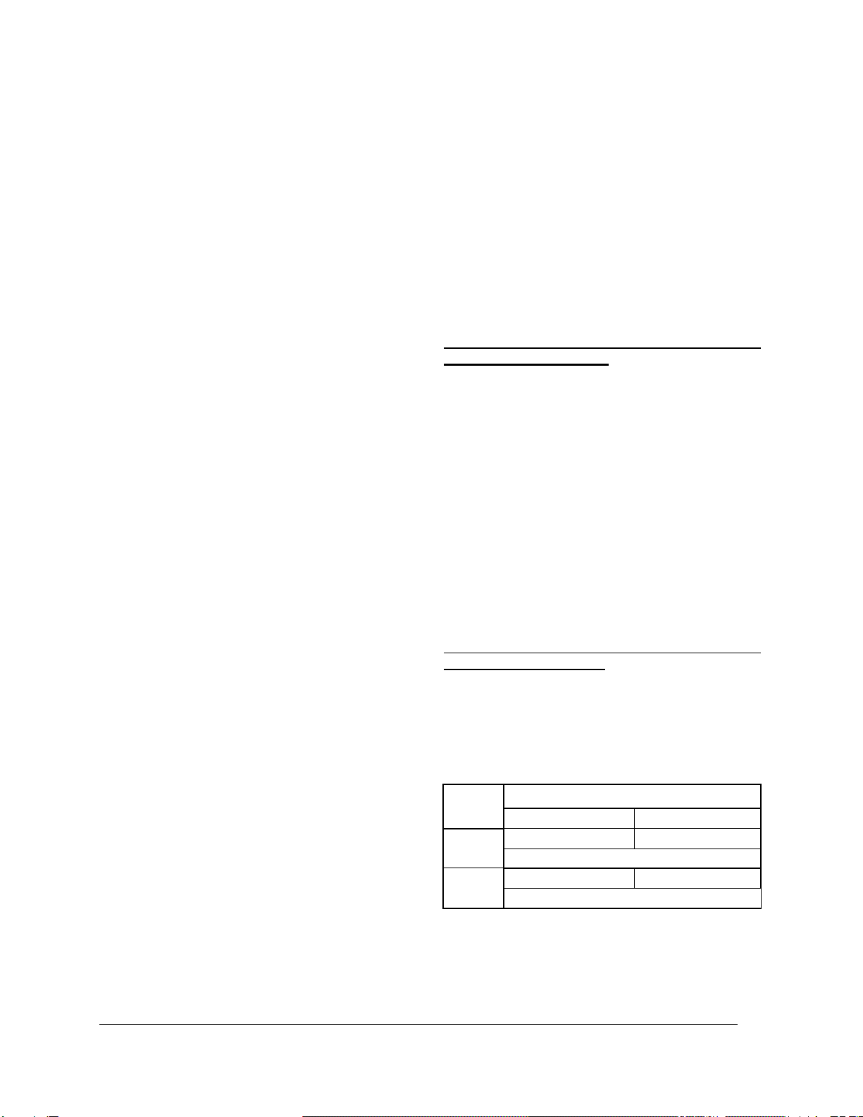
Models
AMPERE @ 208/240 VAC/1ph
Terminal Block #1
Terminal Block #2
27
49/56 Amps
49/56Amps
One terminal block 98/112A
29
52/60 Amps
52/60 Amps
One terminal block 104/120A
Models 33 & 36
The electrical supply must come from two different
electrical circuits. One circuit having three
conductors 120/240V or 120/208V “L1/N/L2” and
the other two conductors 240 or 208V “L1/L2”.
Loading ...
Loading ...
Loading ...