Loading ...
Loading ...
Loading ...
BTH ULTRA Electric Boilers Installation & Operation manual (Revision: June 2015) 13
Both circuits will need to be protected with
appropriate breakers or fuse (see table below
giving the amperage drawn by the boiler on each
breaker) in conformity with local electrical codes.
Connections are made directly on the two
breakers inside the boiler.
These breakers can receive copper or aluminum
cable up to #1AWG..
The boiler can then be operated at approximately
50% of its nominal capacity when the breaker
supplying the electric circuit connected to breaker
#2 is turned OFF during periods of low demand.
Model
Modèle
AMPERE @ 208/240 VAC/1ph
Breaker #1
Breaker #2
33
2 x 5 KW, 1 x 6 KW
2 x 6 KW, 1 x 5 KW
57/66 Amps
61/70 Amps
36
3 x 6 KW
3 x 6 KW
65/75 Amps
65/75 Amps
Alternative #2: No 120Vac electrical supply
is required to serve external accessories
(pump is supplied by a separate circuit
outside the boiler)
The electrical supply is made the same way as
described in alternative #1 excepting that it does
not need the Neutral (N) conductor.
3.5.2 Electrical supply of External
accessories
When the boiler is supplied with a 120V circuit, the
total 120vac consumption of the boiler and
external accessories must not exceed 5A.
The maximum electrical consumption of 24vac
external accessories connected to R&C terminals
must not exceed 15VA.
3.5.3 Outdoor temperature sensor
If you want the boiler target temperature to
modulate according to the outdoor temperature
(when the outdoor temp. will get colder, the target
temp. will get higher). The supplied outdoor sensor
will have to be connected to S1 S1 before turning
the power on to the unit.
The installation of this sensor cancels the
operation of the boiler when the outdoor
temperature exceeds the selected value
corresponding to the maximum temperature
required for heating.
If you wish to operate the boiler at a fixed target
temperature, simply do not connect the sensor
before applying the power to the unit
The sensor shall be connected to terminals S1-S1
in the boiler using two 20 ga conductors.
Maximum length 100 ft. (33 m).
Do not put a jumper between S1&S1 if the outdoor
sensor is not used.
3.5.4 Connecting the thermostat and
pump.
Thermostat: Use a low voltage 24Vac thermostat
designed for central heating system (do not use a
240Vac thermostat designed for electric
baseboards).
Some thermostats are equipped with a
temperature sensor for radiant floor application.
The purpose of the thermostat is to give a signal to
the boiler that there is a demand for heat. When
the boiler will receive this signal, it will control the
activation of the heating elements.
A two stage thermostat could also be installed.
Then the second heating stage would be used to
activate the “Boost” program allowing the boiler
target to be gradually increased (see section
4.10).
Heating systems equipped with one thermostat
and one pump:
With an 18gauge cable, connect the room
thermostat directly to the following boiler terminals.
Two wire thermostat: Terminals “R” and “W”
Three wire thermostat: Terminals “C”, “R” and “W”
Using 14 gauge wires, connect the circulating
pump directly on terminals “P” and “P
N.B. The amperage of the pump and 120Vac
accessories must not exceed 5A or 1/6HP
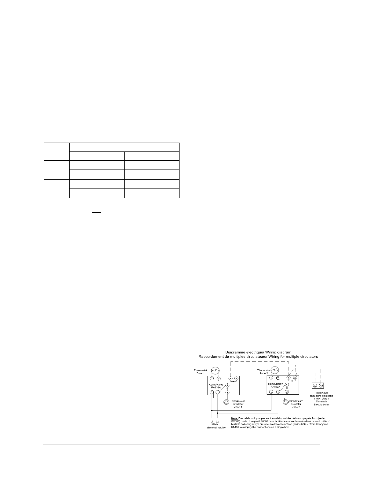
Zoning applications with multiple pumps
Components shall be connected in such a way
that when a thermostat is generating a heat
demand, only the corresponding pump be
operated and that this heat demand is brought to
the boiler in order to activate the elements.
To do so, you will need relays as illustrated below.
Boiler terminals P-P will not be used.
Figure 9 : Zoning with Multiple pumps
Loading ...
Loading ...
Loading ...