Installation Guide - The kit is designed for models #CTMR180M1W, CTMR180M1B, and CTMR180M1S
Before you begin
Read each step thoroughly before proceeding.
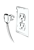
CAUTION – Unplug the Refrigerator.
To eliminate the danger of electric shock during installation, you must unplug the refrigerator from its electrical outlet.
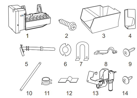
Parts Included

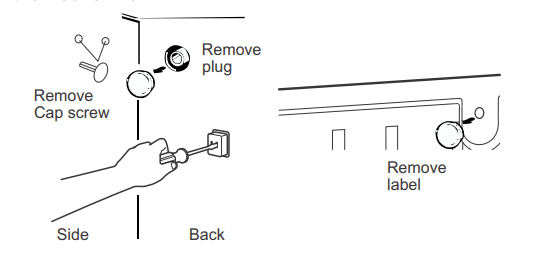
Remove the outlet cover
Go to the back of the refrigerator. Find the small label in the upper right hand corner and peel it off. Then discard the label.
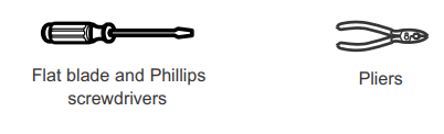
Remove the outlet cover with a ftat-blade screwdriver.
Remove and discard the white plug from the lower left back corner of the freezer wall.
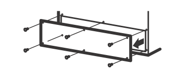
Remove the cover
Use a Phillips head screwdriver to remove the compressor compartment access cover. This requires removing six screws which attach the cover to the back of the refrigerator case.
Be sure to save the screws as the access cover must be reinstalled later to ensure your refrigerator will function properly.
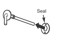
Install Fill Tube
Peel one side of the paper away from the water fill tube seal, slide the seal along the tube and affix to the back side of the water tube inlet flange.
Connect the water line
Make sure there is enough plastic water line to extend from the water valve to well into the water tube inlet. Cut off any excess tubing.
Squeeze the ends of the hose clamp from the kit with pliers and slide the clamp over the water tube inlet.
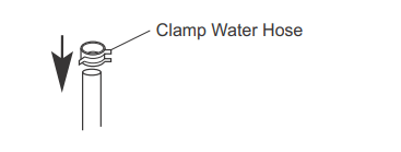
While still squeezing the clamp, insert the plastic water line into the inlet as far as it will go (approximately 1" [ 25 mm]
Then slide the clamp downward to capture the plastic water line in place. Make sure the fill tube is aimed down.
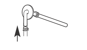
Remove the adhesive backing on the opposite side of the water fill tube seal and slide the tube into the hole near the top at the back of the refrigerator. Firmly press on the inlet to secure it to the refrigerator.
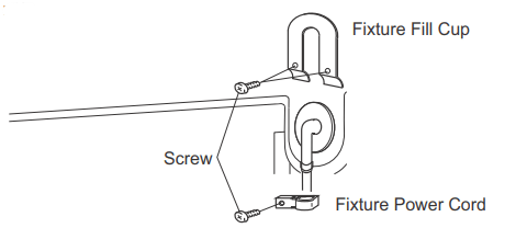
Install Water Line Clamp
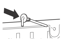
Attach the fixture fill cup and fixture power to the refrigerator. Drive the screw from the kit through the fixtures at the indent into the back of the cabinet.
Route and attach the plastic water line
Fasten the plastic water line to the back of the cabinet with adhesive-backed fasteners, spacing the fasteners as shown to take up slack in the line.

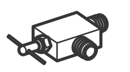
Attach the water valve
Locate the female connector plug. Plug the female connector onto the male terminals on the water valve. Either wire can go on either terminal.
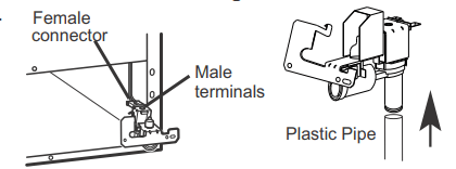
Fasten the water valve to the cabinet by driving the Phillips head screw from the kit into the hole in the cabinet leg.

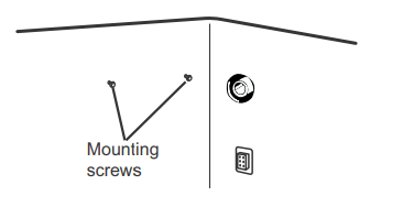
Prepare for Installation
Inside the freezer, loosen the two moungting screws, but do not screw them all the way out. If your model does not have the screws already in the freezer wall, look for two plug buttons. Remove the plug buttons and insert the two phillips head screws. The screws should extend approximately 1/2 ″ (13mm) out from the freezer wall.
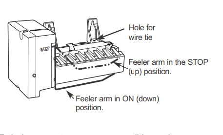
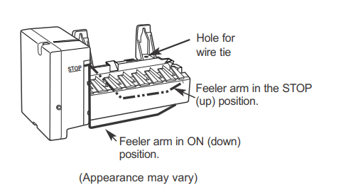
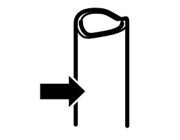
Set feeler arm to Stop position.
Move the feeler arm to the STOP (up) position until the refrigerator is connected to the water supply to prevent premature operation.
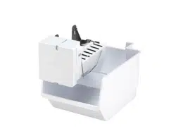
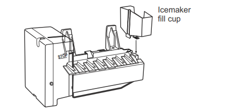
Install the Icemaker Fill Cup
Install the icemaker fill cup (side-mounted) into the icemaker as shown.
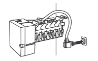
Plug in the Icemaker
Holding the icemaker in place, insert the icemaker power cord plug into the socket on the back wall, making sure the prongs and holes are matched.
Press the plug firmly into the socket. Lock the plug in place by clipping the restraints onto each side of the plug. Make sure the restraints click into place.
Mount the Icemaker
Lift the icemaker so the fill tube extension fits in the fill cup opening. Hang the icemaker on the two screws.
Make sure:
The power cord is still firmly in the socket.
The fill tube extension extends into the fill cup opening at the back of the icemaker.(Check the rear of the refrigerator to make sure the fill tube has not been pushed out of the back of the refrigerator).
The icemaker mounting screws are located in the uppermost position of the mounting slots.
Then securely tighten the icemaker mounting screws.

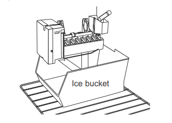
Install the Ice Bucket
Place the ice bucket under the icemaker.
Make sure the icemaker power switch is in the O (off) position.
Water Valve Installed
After water line installation is completed, set the icemaket power switch to I (on).
The icemaking cycle will not begin until the icemaker and freezer compartment reach operating temperature.
Installing the water line
BEFORE YOU BEGIN
This water line installation is not warranted by the refrigerator or icemaker manufacturer. Follow these instructions carefully to minimize the risk of expensive water damage.
Water hammer (water banging in the pipes) in house plumbing can cause damage to refrigerator parts and lead to water leakage or flooding. Call a qualified plumber to correct water hammer before installing the water supply line to the refrigerator.
To prevent burns and product damage, do not hook up the water line to the hot water line.
If you use your refrigerator before connecting the water line, make sure the icemaker power switch is in the O (off) position (on power switch models) or the feeler arm is in the STOP (up) position (on feeler arm models).
Do not install the icemaker tubing in areas where temperatures fall below freezing.
When using any electrical device (such as a power drill) during installation, be sure the device is double insulated or grounded in a manner to prevent the hazard of electric shock, or is battery powered.
All installations must be in accordance with local plumbing code requirements.
WHAT YOU WILL NEED
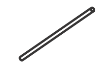
- Refrigerator copper tubing 1/4 outer diameter to connect the refrigerator to the water supply. If using copper, be sure both ends of the tubing are cut square.
- To determine how much tubing you need: Measure the distance from the water valve on the back of the refrigerator to the water supply pipe. Then add 8′ m). Be sure there is sufficient extra tubing to allow the refrigerator to move out from the wall after installation.
- A cold water supply. The water pressure must be between 20 and 120 p.s.i. (1.4–8.1 bar).
- Power drill.
- 1/2 or adjustable wrench.
- Straight and Phillips blade screwdriver.
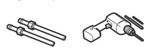
- Two 1/4 ″ outer diameter compression nuts and ferrules (sleeves)—to connect the copper tubing to the shutoff valve and the refrigerator water valve.
- If your existing copper water line has a flared fitting at the end, you will need an adapter (available at plumbing supply stores) to connect the water line to the refrigerator OR you can cut off the flared fitting with a tube cutterand then use a compression fitting.
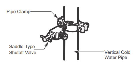
- Shutoff valve to connect to the cold water line. The shutoff valve should have a water inlet with a minimum inside diameter of 5/32 ″ at the point of connection to the cold water line. Saddle-type shutoff valves are included in many water supply kits. Before purchasing, make sure a saddle-type valve complies with your local plumbing codes.
Install the shutoff valve on the nearest frequently used drinking water line.
Shut off the main water supply
Turn on the nearest faucet long enough to clear the line of water.
Choose the valve location
Choose a location for the valve that is easily accessible. It is best to connect into the side of a vertical water pipe. When it is necessary to connect into a horizontal water pipe, make the connection to the top or side, rather than at the bottom, to avoid drawing off any sediment from the water pipe.
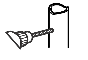
Drill the hole for the valve
Drill a 1/4 ″ hole in the water pipe (even if using a self-piercing valve), using a sharp bit. Remove any burrs resulting from drilling the hole in the pipe.
Take care not to allow water to drain into the drill.
Failure to drill a 1/4 ″ hole may result in reduced ice production or smaller cubes.
Fasten the shutoff valve
Fasten the shutoff valve to the cold water pipe with the pipe clamp.
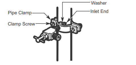
Tighten the pipe clamp
Tighten the clamp screws until the sealing washer begins to swell.
Route the tubing
Route the tubing between the cold water line and the refrigerator.
Route the tubing through a hole drilled in the wall or floor (behind the refrigerator or adjacent base cabinet) as close to the wall as possible.
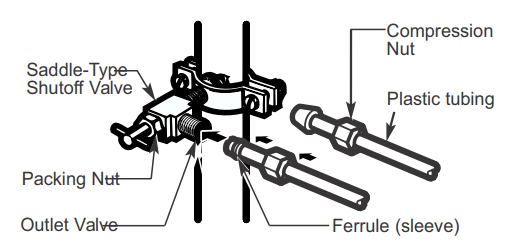
Connect the tubing to the valve
Place the compression nut and ferrule (sleeve) for copper tubing onto the end of the tubing and connect it to the shutoff valve.
Make sure the tubing is fully inserted into the valve.
Tighten the compression nut securely.
For plastic tubing, insert the molded end of the tubing into the shutoff valve and tighten compression nut until it is hand-tight; then tighten one additional turn with a wrench. Overtightening may cause leaks.
Flush out the tubing
Turn the main water supply on and flush out the tubing until the water is clear.
Shut the water off at the water valve after about one quart (1 liter) of water has been flushed through the tubing.

Connect the tubing to the Refrigerator
Remove the screws holding the right side of the access cover. Fold back the cover.
Remove the plastic flexible cap from the water valve (refrigerator connection).
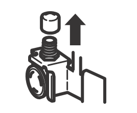
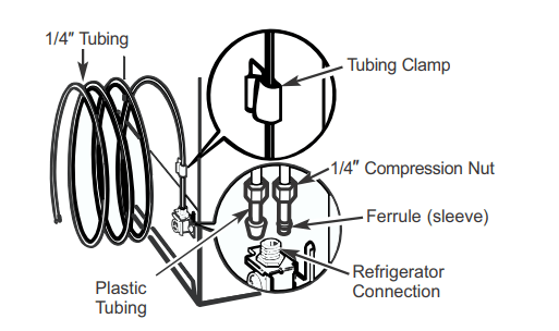
Place the compression nut and ferrule (sleeve) onto the end of the tubing as shown.
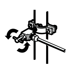
Insert the end of the tubing into the water valve connection as far as possible. While holding the tubing, tighten the fitting.
For plastic tubing, insert the molded end of the tubing into the water valve connection and tighten compression nut until it is hand-tight; then tighten one additional turn with a wrench.
Overtightening may cause leaks.
Fasten the tubing into the clamp provided to hold it in a vertical position. You may need to pry open the clamp.
One of the illustrations below will look like the connection on your refrigerator.
Turn the water on at the shutoff valve
Tighten any connections that leak.
Reattach the access cover.
Plug in the refrigerator
Arrange the coil of tubing so that it does not vibrate against the back of the refrigerator or against the wall. Push the refrigerator back to the wall.

The power cord of this appliance is equipped with a 3-prong (grounding) plug that mates with a standard 3-prong (grounding) wall receptacle to minimize the risk of electric shock hazard from this appliance. The customer should have the wall receptacle and circuit checked by a qualified electrician to make sure the receptacle is properly grounded.
Where a standard two-prong wall receptacle is encountered, it is the personal responsibility and obligation of the customer to have it replaced with a properly grounded 3-prong wall receptacle.
Do not, Under any circumstances, cut or remove the third (ground) prong from the power cord.
Start the Icemaker
Move the feeler arm to the ON (down) position. The icemaker will not begin to operate until it reaches its operating temperature of 15°F (–9°C) or below. It will then begin operation automatically