INSTRUCTIONS PERTAINING TO A RISK OF FIRE, ELECTRIC SHOCK OR INJURY TO PERSONS. SAVE THESE INSTRUCTIONS.
WARNING – When using electrical appliances, basic precautions should always be followed, including the following:
1. Read all instructions before using the appliance.
2. To reduce the risk of injury, close supervision is necessary when an appliance is used near children.
3. Do not put fingers or hands into a waste disposer.
4. Turn the power switch to the off position before attempting to clear a jam or remove an object from the disposer.
5. When attempting to loosen a jam in a waste disposer, use a long wooden object such as a wooden spoon or the wooden handle of a broom or mop.
6. When attempting to remove objects from a waste disposer use long-handled tongs or pliers. If the disposer is magnetically actuated, non-magnetic tools should be used.
7. To reduce the risk of injury by materials that may be expelled by a waste disposer, do not put the following into a disposer: clam or oyster shells; caustic drain cleaners or similar products; glass, china or plastic; large whole bones; metal, such as bottle caps, tin cans, aluminum foil or utensils; hot grease or other hot liquids; whole corn-husks.
8. When not operating a disposer, leave the stopper in place to reduce the risk of objects falling into the disposer.
9. DO NOT operate disposer unless splash guard is in place.
10. For proper grounding instructions see the ELECTRICAL CONNECTIONS portion of this manual.
1. REMOVAL OF OLD UNIT
TYPICAL INSTRUCTIONS, YOUR MODEL MAY VARY
Before starting this step, turn off electrical power at the circuit breaker or fuse box. Unplug disposer.
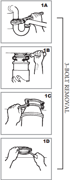
If your old mount is the same type (3-Bolt Mount) as the mount on your new Criterion® disposer and you wish to continue using the old mount, just remove your old disposer as shown below in parts 1A,-1B, & 1C then skip to Step 2 section I.
If your old mount is the same type as the mount on your new Criterion® disposer and you do not wish to use the old mount you can remove the old mount as follows:
A. Have a container available to catch any excess water / waste from current disposer.
B. Use a pipe wrench to disconnect drain line where it attaches to disposer discharge elbow (see 1A).
C. Remove disposer from sink flange by turning mount ring to the left clockwise (see 1B). If you are unable to turn the mount ring, tap on one of the extensions from the ring with a hammer. Some mounting systems have tubular extensions. Inserting a screwdriver into one tube will provide additional leverage for turning the mount ring (see 1B). Some disposers may require the removal or loosening of nuts from the mount screws (see 1C). Some disposers may require the removal of a clamp.
Caution: Be sure to support the disposer while performing this step or it may fall when the mounting ring is disconnected from the mounting assembly.
D. To remove remaining mount system from the sink, loosen mount screws, and push mount ring up. Under it is the snap ring. Use a screwdriver to pop off the snap ring (see 1D). Remove mount ring, protector ring and gasket from sink flange. Some mounts will require the unscrewing of a large ring holding the sink flange in place. Pull the sink flange up through sink and clean off old putty from sink.
E. Ensure that sink is clean and thoroughly dry.
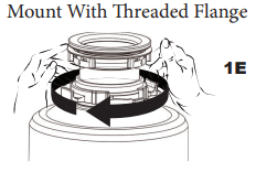
If you have a mount system under the sink that is black plastic with threads:
A. While holding the disposer in place, turn the metal mount ring clockwise (1E). If it is hard to turn, tap the ear of the mount ring clockwise.
B. When the disposer hopper projections get close to the mount ring opening, hold the disposer from bottom and disengage it from the mount ring.
C. Remove the rubber cushion mount from under the mount ring.
D. Remove the mount ring. Unthread the black support ring from sink flange by turning the support ring clockwise. Remove the fiber gasket and then remove the sink flange from above the sink.
E. Ensure that sink is clean and thoroughly dry.
IMPORTANT: This is a good time to clean out the trap and drain lines by running a drain auger or plumber’s snake before installing your new disposer.
Mount With Threaded Flange
2. INSTALLATION OF MOUNTING ASSEMBLY
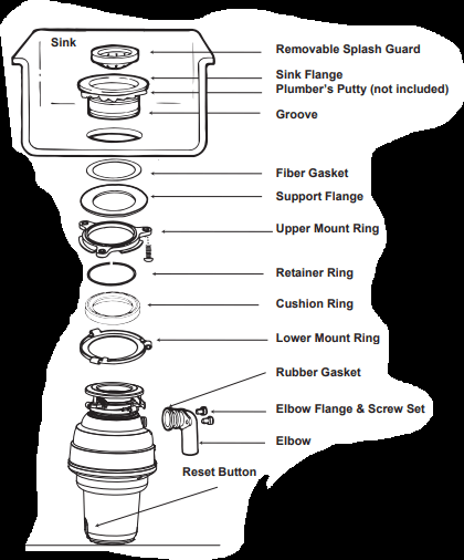
STOPPER or STOPPER/SCRAPER (750 & 1250 Model)
REMOVABLE SPLASH GUARD
SINK FLANGE
FIBER GASKET
SUPPORT FLANGE
UPPER MOUNT RING
MOUNT SCREWS
RETAINER RING
CUSHION RING*
LOWER MOUNT RING*
SILVER GUARD® MAGNETIC CATCH RING
Attachment included with the 1250 model. Installation instructions on last page.
Snap-Fast® Tool for easy installation of the retainer ring.
NOTE: As the mounting assembly is properly assembled at the factory, please pay close attention to the order of the mounting system parts.
NOTE: Cushion Ring included between the Upper Mount Ring and Lower Mounting Ring.
* Part not disengaged during disposer installation.
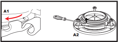
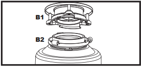
A. The Cushion Ring and the Lower Mount Ring will remain attached to the disposer during installation. Take apart the other parts of the mounting assembly by rotating the Lower Mount Ring (J on page 3) clockwise until the Lower Mount Ring Tabs slide off from the Upper Mount Ring ramp (A1). This allows you to pull the Sink Flange up and out of the remaining Lower Mount Assembly. Note the order of these parts as they are arranged in the required order. Unscrew the 3 Mount Screws until the Upper Mount Ring can be moved to the top of the Support Flange. Remove the Retainer Ring with a flat head screw driver.(A2)
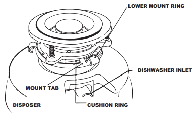
B. Keep the remaining parts placed together in the order they were removed (B1). Before you connect the disposer to the mount assembly under the sink, make sure the Lower Mount Ring is in place and the black Cushion Ring is still engaged properly to the top of the disposer hopper (B2).
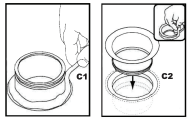
C. Be sure the sink is clean. Load the underside rim of the sink flange with plumber's putty (C1). From top of the sink, push the sink flange down against the sink opening to make a good seal (C2). DO NOT MOVE OR ROTATE the sink flange once it has been seated or the seal may be broken.
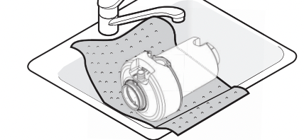
D Place a heavy object, such as the disposer (use a towel to prevent sink scratching) on top of the Sink Flange to hold it down.
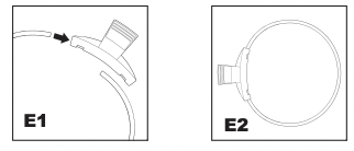
E. Prepare the retainer ring for installtion using the Snap-Fast® tool by inserting each end of the retainer ring unto the ends of the tool (E1) until it is securely affixed (E2).
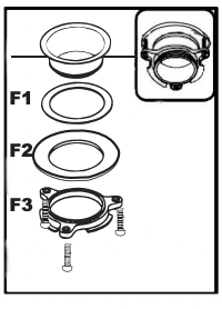
F. Take the remaining portion of the mount assembly, that was put aside. From under the sink insert the Fiber Gasket (F1), then the Support Flange (F2), and then the Upper Mount Ring (F3).
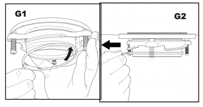
G. Hold the three parts in place while attaching the retainer ring (G1) by sliding the far end of the ring into the groove on the lower end of the sink flange. Align the retainer ring horizontally in place then pull the Snap-Fast® clip away from the flange. This will release the retainer ring from the Snap-Fast® clip which allows the ring to snap into place within the groove.(G2).
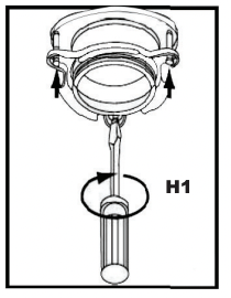
H. Tighten the three Mount Screws evenly and firmly against the Support Flange (H1). Do not over tighten.
I. Trim off any excess plumber’s putty in the sink with a plastic knife or something similar that will not damage your sink.
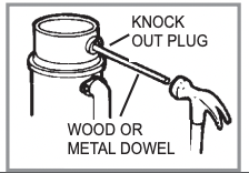
DISHWASHER CONNECTION PREPARATION
If you are utilizing a dishwasher, complete the following procedure.
Using a blunt instrument (steel punch or wooden dowel), knock out entire plug. Do not use a screwdriver or sharp instrument. (When knockout plug falls into disposer, you may remove it or grind it up when the disposer is used. This will not damage the disposer in any way, but it may take some time to grind).
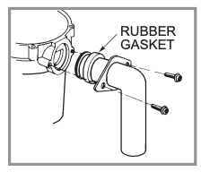
ATTACHING DISCHARGE ELBOW
Connect the waste elbow to the disposer with the Elbow Flange and Screw Set provided.
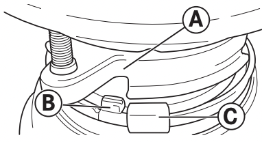
LOCKING MOUNTING ASSEMBLY DETAIL
Attach disposer onto the Upper Mount Ring by aligning the three mount tabs on the Lower Mount Ring with the slide-up Ramps on the Upper Mount Ring and rotating counter clockwise. See Below
The lower mounting ring (which is part of the disposer) has 3 tabs that grab the mounting ring ramp.
(A) points to the Upper Mount Ring.
(B) is the tab that slides up onto the “Ramp”.
(C) is the "Ear" that is used to help rotate the Lower Mount Ring. Use a screwdriver for leverage if needed.
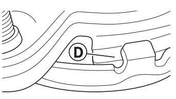
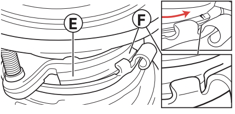
Lift and turn the Lower Mount Ring counter clockwise until all three mount tabs lock over the Ridges (F) on the slide-up Ramps (D) of the Upper Mount Ring.
As the Lower Mount Ring is turned counter clockwise each tab slides up onto the Upper Mount Ring Ramp (E) and locks in position over the Ridges (F).
Use a screwdriver or hammer for leverage if needed.
If a disposer needs to be removed, tapping on the Ear clockwise with a hammer will easily loosen the Lower Mount Ring.
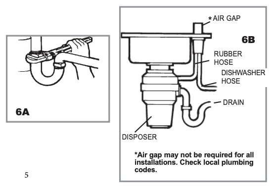
DISCHARGE ELBOW & DISHWASHER CONNECTIONS
A. Connect bottom of the elbow by tightening the slip nut (see 6A). If you are connecting to a dishwasher, see B. If not, make sure all plumbing connections are tight and in accordance with all plumbing codes and ordinances. Run water and check for leaks.
B. Connect dishwasher hose (6B) using a hose clamp. Make sure all plumbing connections are tight and in accordance with all plumbing codes and ordinances. Run water and check for leaks.
ELECTRICAL CONNECTIONS
A. Connect the disposer to appropriate household current only
The receptacle to which this appliance is connected must be controlled by a switch.
WARNING: IMPROPER CONNECTION OF THE EQUIPMENT-GROUNDING CONDUCTOR CAN RESULT IN A RISK OF ELECTRIC SHOCK. CHECK WITH A QUALIFIED ELECTRICIAN OR SERVICEMAN IF YOU ARE IN DOUBT AS TO WHETHER THE APPLIANCE IS PROPERLY GROUNDED. DO NOT MODIFY THE PLUG PROVIDED WITH THE APPLIANCE IF IT WILL NOT FIT THE OUTLET. HAVE A PROPER OUTLET INSTALLED BY A QUALIFIED ELECTRICIAN.
GROUNDING INSTRUCTIONS
FOR WASTE DISPOSERS EQUIPPED WITH A GROUNDED PLUG-IN POWER CORD.
B. This appliance must be grounded. In the event of a malfunction or breakdown, grounding provides a path of least resistance for electric current to reduce the risk of electric shock. This appliance is equipped with a cord having an equipment-grounding conductor and a grounding plug. The plug must be plugged into an appropriate outlet that is properly installed and grounded in accordance with all local codes and ordinances. If the supply cord is damaged it must be replaced by the manufacturer, its service agent or similarly qualified person in order to avoid a hazard. Removing an attached power cord or plug voids the warranty.
PERMANENT WIRE INSTALLATION INSTRUCTIONS
FOR WASTE DISPOSERS NOT EQUIPPED WITH A GROUNDED PLUG-IN POWER CORD.
GROUNDING: This disposer must be connected to a grounded, metal, permanent wiring system; or an equipment-grounding conductor must be run with the circuit conductors and connected to the equipmentgrounding terminal or lead on the disposer.
An acceptable motor control switch with a marked off position shall be provided at the time of installation to disconnect the disposer from all ungrounded supply conductors. The switch shall be mounted in sight of the disposer or in sight of the sink opening for the disposer.
Turn off or disconnect all power to the wall junction box serving the disposer.
Open the junction box in the wall and remove the wire nuts or electrical tape or whatever is tying the old disposer wire to the electrical wire inside of the junction box.
Open the end bell plate at the bottom or the disposer.
If you are using flexible armored (BX) cable:
Install cable fitting in the disposer end bell hole.
Secure the cable to the fitting and install an insulating bushing or equivalent.
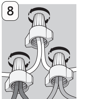
Connect white wire from the junction box to the white or blue) wire of the disposer.
Connect black wire from the junction box to the black or brown) wire of the disposer.
Connect bare ground wire from the junction box to green ground screw within the disposer end bell.
WARNING: Electric Shock
Turn off power before installing or servicing disposer. All wiring must comply with local electrical codes.
Do not connect electrical current at main breaker panel until adequate ground is established. Inadequate connection of the ground wire can result in a risk of electric shock. Consult with a certified electrician or tradesman if there is any doubt whether the disposer in inadequately grounded. Your disposer must be adequately grounded.
If you are using nonmetallic-sheathed (ROMEX) cable:
Install cable fitting in the end bell hole and secure the cable to the fitting.
Connect white wire from the junction box to the white or blue) wire of the disposer.
Connect black wire from the junction box to the black or brown) wire of the disposer.
Connect bare ground wire from the junction box to green ground screw within the disposer end bell.
If your power supply cable does not include a grounding wire, one must be provided. Attach a copper wire securely to the disposer ground screw and attach other end of ground wire to a metal cold water pipe. Do not attach ground wire to a gas supply pipe. Use only UL Listed grounding clamp. If plastic pipe is used in your home, a qualified electrician should install a proper ground.
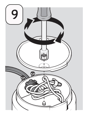
1. After turning off power supply, unbolt two nuts and remove end plate.
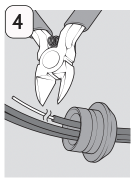
2. Using a flathead screwdriver or needle nose pliers, remove clip from strain relief portion of the cord.
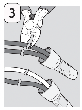
3. Using wire cutters, cut black (or brown) wire and white (or blue) wire near the connectors.
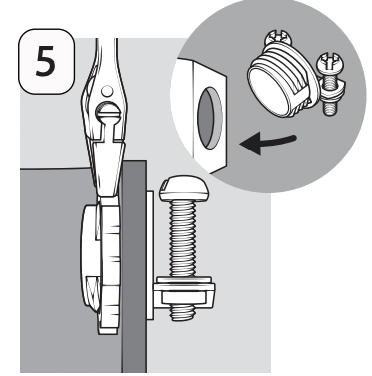
4. Pull cord strain relief out of endbell. Cut green ground wire near the cord strain relief.
5. Insert metal strain relief connector (not included) into the endbell hole and tighten the nut securely.
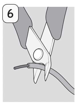
6. Strip the green, black, and white insulation from last ½” of each wire.
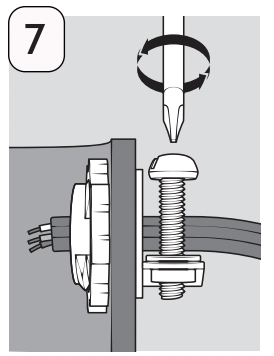
7. Insert the power supply cable, coming from the wall junction box, through the strain relief connector. Tighten connector.
8. Connect disposal wire leads (black and blue) to corresponding wire leads of the power supply cable. Green always connects to green.
9. Setting the wires into the endbell, replace the end plate and tighten the two bolts.
OPERATING INSTRUCTIONS
The Anti-Jam Swivel Impellers make a clicking sound as they initially swing into place. This indicates normal operation.
A. Remove sink stopper. Turn on a medium flow of cold water.
B. Turn switch to ON position; your motor is turning at full speed and ready to use.
C. Scrape in food waste. Down the drain go table scraps, peelings, rinds, seeds, pits, small bones and coffee grounds. To speed up food waste disposal, cut or break up large bones, rinds and cobs. Large bones and fibrous waste require considerable grinding time and are more easily thrown away with other trash. Do not be alarmed that the disposer slows down while grinding. The disposer is actually increasing torque grinding power) and is operating under normal conditions.
D. Before turning the disposer off, let water and disposer run for approximately 15 seconds after shredding or grinding stops. This assures that all waste is thoroughly flushed through trap and drain.
E. It is not recommended to use hot water while running disposer. Cold water will keep waste and fats solid so disposer can flush away particles.
TIPS FOR SUCCESSFUL OPERATION
A. Be sure disposer is empty before using your dishwasher so it may drain properly.
B. You may want to leave the stopper in the sink drain when not in use to prevent utensils and foreign objects from falling into the disposer.
C. Your disposer is ruggedly built to give you many years of trouble free service. It will handle all normal food wastes, but it will NOT grind or dispose of such items as plastic, tin cans, bottle caps, glass, china, leather, cloth, rubber, string, clam and oyster shells, aluminum foil or feathers.
CLEANING AND MAINTENANCE
DO NOT ATTEMPT TO LUBRICATE YOUR DISPOSER!
The motor is permanently lubricated. The disposer is self cleaning and scours its internal parts with each use. NEVER put lye or chemical drain cleaners into the disposer, as they cause serious corrosion of metal parts. If used, resulting damage can be easily detected and all warranties are void. Mineral deposits from your water can form on the stainless steel turntable, giving the appearance of rust. DO NOT BE ALARMED, the stainless steel turntables used will not corrode.
TROUBLESHOOTING
Before seeking repair or replacement, we recommend that you review the following:
LOUD NOISES: (Other than those during grinding of small bones and fruit pits): These are usually caused by accidental entry of a spoon, bottle cap or other foreign object. To correct this, turn off electrical switch and water.
After disposer has stopped, remove splash guard, remove object with long handled tongs, and replace splash guard.
UNIT DOES NOT START: Unplug power cord or turn either the wall switch or breaker box switch to “OFF” position, depending on your model and wiring configuration. Remove stopper and/or splash guard. Check to see if turntable will rotate freely using a wooden broom handle. If turntable rotates freely, replace splash guard and check reset button to see if it has been tripped. Reset button is red and located on the front of the disposer. Push button in until it clicks and remains depressed.
If reset button has not been tripped, check for shorted or broken wire connecting to disposer. Check electrical power switch, fuse box or circuit breaker. If wiring and electrical components are intact, the unit may have internal problems that require service or replacement.
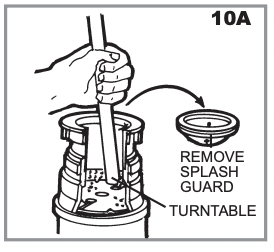
IF TURNTABLE DOES NOT ROTATE FREELY: Turn off disposer, then check for any foreign object lodged between the turntable and grind ring. Dislodge object by rotating table with a wooden broom handle (see 10A) and remove object. If no foreign object is present, there may be internal problems.
LEAKS: If the unit leaks at the top, it may be due to:
1. Improper seating of sink flange (gasket centering, putty or tightening).
2. Support ring not tightened properly.
3. Defective or improperly installed cushion mount. If unit leaks at the waste elbow, leak may be due to improper tightening of elbow flange screws.
 STOPPER or STOPPER/SCRAPER (750 & 1250 Model)
 REMOVABLE SPLASH GUARD
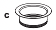 SINK FLANGE
 FIBER GASKET
 SUPPORT FLANGE
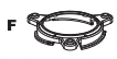 UPPER MOUNT RING
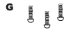 MOUNT SCREWS
 RETAINER RING
 CUSHION RING*
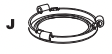 LOWER MOUNT RING*
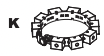 SILVER GUARD® MAGNETIC CATCH RING
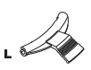 Snap-Fast® Tool for easy installation of the retainer ring.