Carefully check the unit for damage and/or missing parts prior to installation. If there is any damage or if you are missing parts, do not proceed with the installation. Report damage and/or missing parts immediately to our customer service team at cs@conglomkb com or 1-888-449-9194 (Service available in English and French, Monday - Friday from 8:30 am - 5:00 pm EST). Please do not dispose of packaging before you are satisfied with your new product.
Part
Description
Quantity
A
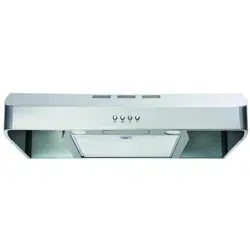
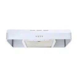
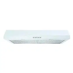
Range hood
1
B
Aluminum & charcoal filter
1
C
Rectangular damper (located inside the hood)
1
D
Round adapter (located inside the hood)
1
HARDWARE INCLUDED
NOTE:
Parts not shown in actual size.
Part
Description
Quantity
AA
Long tapping screws (ST4x18mm)
4
BB
Short tapping screws (ST4x10-F-Hmm)
8
CC
Wire Connectors
3
PLANNING INSTALLATION
Number of people required: 2 or more
1 . Before installation, measure all distances to ensure the proper position of the range hood (A).
- The minimum distance (1) from the cooking surface to the range hood is 18 in. (458 mm). If your range specifies a different distance, use the greater distance of the two. For best performance, this distance (1) should not exceed 25 in. (635 mm).
- Dimension (2) should be at least 30 in (762 mm). The range hood should be approximately the same size as the cook top .
2. If the bottom of the cabinet (3) above the location where the range hood is to be installed is recessed, attach appropriately sized wood filler strips (4) on each side using wood screws.
3 . Screws are provided to secure the range hood to most types of cabinets, but consult a qualified installer to verify that the supplied screws are suitable for your cabinets .
4 . Put a thick, protective covering over your counter, cooktop, or range to protect it from damage and dirt during installation . Remove any hazardous objects around the area .
WARNING: Always wear safety goggles and gloves during installation .
VENTING OPTIONS:
a . Determine if your existing venting system is top venting or back venting, and ensure that the openings in the cabinet or wall for the damper and for power access are in appropriate locations and are of appropriate sizes, as per Fig . 3 if it is top venting or Fig. 4 if it is back venting. For top venting option (Fig. 3), if you are using the round adapter, the opening should be A and B only . If you are using the rectangular damper, opening should be B and C only .
b . If this is a new installation, choose the venting method that suits your needs . Cut out openings for the damper and for power access in the cabinet bottom or exterior wall, depending on the direction of venting chosen .
FOLLOW THESE GUIDELINES WHEN INSTALLING DUCT WORK:
- Your venting system must vent to the outdoors either horizontally through the back wall (13) or vertically through the roof (14) (refer to Fig. 5/Fig. 6/Fig. 7).
- Use round metal duct work with a uniform diameter of 177 mm (7 in). The total duct run in the venting system should not be more than 10.7 m (35 ft).
- Calculate the total effective length of the duct work by adding the equivalent lengths in the table shown (Fig. 9). For each fitting used add the length of the equivalent straight duct used in the system.
- Fasten all connections between pieces of duct with sheet metal screws and tape all joints with certified duct tape.
- If you must turn the path of the duct work using elbows, keep the number of elbows to a minimum for effective performance and use no more than three 90° elbows. Ensure that there is a minimum of 458 mm (18 in) of straight vent between each elbow. Elbow as far away from the range hood’s exhaust opening as possible .
- Cap the exterior of the duct with a wall cap (15) or roof cap (16). Never use 102 mm (4 in) laundry-type wall caps. Use caulking to seal exterior wall or roof opening around the cap .
- The venting system must have a damper. If the roof or wall cap has a damper, do not use the damper supplied with the range hood
For inside venting system (air does not exhaust to outdoors) (Fig. 8):
Please refer to the Installation section .A vent cover plate will be removed and air will be exhausted through the charcoal filter and out from 17 .
Equivalent Length Chart
Type of duct
Length added
45° Elbow
0.91 m (3 ft)
90° Elbow
1.52 m (5 ft)
90° Flat elbow
3.66 m (12 ft)
2.74 m (9 ft) Straight duct
2.74 m (9 ft)
Wall cap
0 m (0 ft)
Fig .9
WIRING CONNECTION REQUIREMENTS
Installation work and electrical wiring must be done by a qualified person(s) in accordance with all applicable codes and standards, including fire-rated construction.
OBSERVE ALL GOVERNING CODES AND ORDINANCES WARNINGS
- Electrical grounding is required for this range hood . Check with a qualified electrician if you are not sure whether the range hood is properly grounded .
- Failure to follow electrical requirements may result in a fire.
- A fuse in the neutral or grounding circuit could result in electrical shock
- If the hot/cold water pipe is interrupted by plastic nonmetallic gaskets or other materials, DO NOT use for grounding .
- DO NOT GROUND TO A GAS PIPE .
IMPORTANT: It is the customer’s responsibility to contact a qualified electrical installer and assure that the electrical installation is adequate and complies with the National Electrical Code, or CSA standards, as well as all local codes and ordinances
3 . Save installation instructions for electrical inspector’s use .
4 . If codes permit and a separate ground wire is used, it is recommended that a qualified electrician determine if the ground path is adequate
5 . DO NOT use an extension cord or adapter plug with this appliance
6 . The range hood must be connected with copper wire only.
7 . The range hood should be connected directly to the junction (or circuit breaker) box through flexible, armoured or nonmetallic sheathed copper cable . Allow some slack in the cable so the appliance can be moved if servicing is ever necessary.
8 . A UL listed or CSA approved conduit connector must be provided at each end of the power supply cable (at the range hood and at the junction box).
9 . When making the electrical connection, cut a 3.2 cm (1- 1/4 in hole in the wall . A hole cut through wood must be sanded until smooth . A hole through metal must have a grommet
10. When cutting or drilling into the wall or ceilling, do not damage electrical wiring and other hidden utilities .
11. Wire size must conform to all local codes and ordinances . The latest edition requirements of the National Electrical Code ANSI/NFPA 70, or the latest edition CSA Standards C22.1-94, Canadian Electrical Code Part 1 and C22.2 No. 0-M91.
NOTE:
Temporarily wire the range hood to test it for proper operation. If the range hood does not operate correctly, do not proceed with the installation.
- Remove the electrical junction compartment door of the range hood to access the electrical wire leads .
- Use the power supply cable to connect the range hood (A) directly to the junction box or circuit breaker box. Use a flexible, armoured, or nonmetallic sheathed copper cable only. Never use an extension cord or adapter plug .
- Connect a UL-listed or CSA-approved conduit connector to each end of the power supply cable (at the range hood and at the junction box). Connect the 2 colored wires from the range hood (A) to the corresponding wires from the electrical source: black to black (live), white to white (neutral), and the house grounding wire to the green ground screw. Use either the top hole (1) or the back hole (2) of the range hood depending on your installation type as shown in Fig. 10.
- Reinstall the electric junction compartment door of the range hood
- Turn the power on, and ensure that the lights and the fan are operating correctly
- Once you have tested the electrical connection, disconnect the power supply cable and wires from the electrical source before proceeding with the rest of the installation .
Installation
WARNING: FUEL (GAS) BURNING RANGES MUST BE VENTED OUTDOORS USING, AT MINIMUM, METAL DUCTWORK AND RANGE HOODS OF SUFFICIENT CAPACITY. Follow your fuel burning equipment manufacturer's guidelines, as well as, all applicable safety standards published by the National Fire Protection Association (NFPA), and the American Society for Heating, Refrigeration and Air Conditioning Engineers (ASHRAE), and your local code authorities.
REMOVING THE ELECTRICAL KNOCKOUT HOLE
WARNING: Always wear safety goggles and gloves during installation.
- Choose the appropriate electrical knock-out hole to remove for your installation type. Use the top hole (1) if your electrical supply is in the cabinet and the back hole (2) if your electrical supply is on the wall below the cabinet (refer to Fig. 10).
- Use a hammer and a flathead screwdriver to gently punch out the electrical knock-out hole.
REMOVING THE VENTING HOLE
(FOR EXTERIOR VENTING)
- Choose the venting hole to remove for your installation type. Use the top holes (3 & 4) for a top venting installation and the back hole (5) for a back venting installation .
- Carefully remove the cover (3, 4 or 5) of the appropriate venting hole using a flat head screwdriver or needle nose pliers (refer Fig. 11). Be careful not to leave any debris inside the range hood (A).
(FOR INTERIOR VENTING)
- If you are venting indoors, unscrew the screw holding cover (6) in place and remove the cover as per Fig. 12 . DO NOT REMOVE ANY OTHER VENTING HOLE COVER .
INSTALLING THE DAMPER
(SKIP THIS STEP IF YOU ARE USING INTERIOR VENTING)
NOTE:
Only install the damper if you are using a venting system that does not already have a damper. If this hood replaces an existing unit, the location of the air exhaust can vary from one manufacturer to another. Ensure that the damper fits in the existing opening before installing.
- The damper and the adapter are located inside the range hood . To access these parts, remove the bottom panel (E) if you have not previously done so (see Fig. 13).
- Choose to install the damper (C) either in the top position (3) for top venting or in the back position (5)
for back venting. Adapter (D) installs to position 3 & 4 for top venting only.
- Attach damper (C) or adapter (D) over chosen knockout opening . Make sure the damper pivot is oriented on top such that the damper stays closed when not in use .
- Secure the damper (C) or adapter (D) to the range hood (A) with the short tapping screws (BB).
- Seal the damper (C) or adapter (D) to the range hood (A) on all four sides with duct tape .
INSTALLING THE RANGE HOOD
DANGER: Turn off the power circuit breaker or the power switch on the junction box before installing this unit . Touching circuitry inside the range hood while it is energized will result in death or serious injury .
DANGER: If installing this unit over a gas range, turn off the gas at the source before installing or servicing this unit
- Lift the range hood (A) up under the cabinet to determine its final position. Mark the location of the four keyhole mounting slots (1) on the underside of the cabinet .
- Set the range hood (A) aside on a protective surface .
- Drill four pilot holes in the locations that you marked .
- Screw the four long tapping screws (AA) into the pilot holes . Do not tighten the screws all the way -leave the screw heads about 7 mm (0.28 in) from the cabinet surface .
- Lift the range hood (A) into position, feeding the power cable and the electrical wires through the power access opening . Allow some slack in the cable and wires so that the appliance can be moved if servicing is ever necessary.
- Position the range hood (A) so the large end (2) of the keyhole mounting slots (1) are over the screws (AA). Then push the range hood (A) toward the wall so the screws (AA) are in the neck (3) of the keyhole slots. Tighten the screws (AA). Ensure that the range hood (A) is securely fastened to the cabinet before releasing it .
- If applicable, test the damper blade to ensure it rotates up and down freely.
- If applicable, connect the duct work to the range hood (A). Seal the joints with duct tape to ensure an airtight fit.
FINAL STEP
- Reconnect the power supply cable and wires to the electrical supply. Turn the power on and ensure that the lights and fan are operating correctly.
INSTALLING THE CHARCOAL FILTER
(SKIP THIS STEP IF YOU ARE USING EXTERIOR VENTING)
NOTE:
The charcoal filter should only be installed if you are not using an external venting system.
- Turn the filter clip to either side and lift the aluminum filter.
- Place the charcoal filter (B) in place, ensure that it covers the air outlet entirely.
- Turn the filter clip so that the end of the clip holds the filter firmly in place.
Operation
NOTE:
The fan and lights operate independently of each other.
TURNING ON/OFF THE UNIT
- To turn on the fan, press the appropriate speed control switch [Low Speed (3), High Speed (2)] to select the desired level of power . Once a button is pressed, the previous speed mode will be cancelled .
- Press the power switch (4) to turn off the fan.
TURNING ON/OFF THE LIGHTS
- Press the light switch (1) to turn on the lights.
Maintenance
REPLACING FILTERS
When filters need replacing, exchange with similar. Also replace filters that are damaged with punctures, bends, or broken frames .
- Turn off the range hood and disconnect the power.
- Replace with an equivalent filter, then reconnect the power.
DANGER: Turn off the power circuit breaker or the power switch on the junction box before performing maintenance . Touching circuitry inside the range hood while it is energized will result in death or serious injury .
WARNING: Failure to replace worn out or damaged filters will increase the risk of fire.
REPLACING LIGHT BULBS
When light bulbs burn out, replace them with a 5W GU10 base light bulb.
- Turn off the range hood, disconnect it from its power source, and ensure that the lights are cool .
- Turn the bulb (1) in the direction indicated and pull it out to remove it .
- Push in the new bulb (2) and turn it in the direction indicated until it locks into the socket .
Do not release the bulb until you are sure the bulb has been securely installed . Then reconnect the power
- If new bulbs do not operate, ensure that they are inserted correctly.
WARNING: Light bulbs can become hot when turned on . Do not touch bulbs until they are switched off and cooled . Touching hot bulbs could cause serious burns
Care and Cleaning
RANGE HOOD
WARNING: Failure to maintain basic standards of care and cleaning of the range hood will increase the risk of fire
The range hood should be cleaned (regularly internally and externally) to preserve its appearance and performance.
Do:
Do Not:
- Always clean in the direction of the grain (original polish lines).
- Clean the range hood periodically with hot, soapy water and a clean cotton cloth .
- Always rinse well with clean water two or three times after cleaning . Wipe completely dry with a soft non-abrasive cloth.
- After cleaning, you may polish with a nonabrasive stainless steel polish or cleaner. Always rub lightly and with the grain
- Ensure that the venting system is free of debris, if you have one .
- Do not use corrosive or abrasive detergents, steel wool, or scouring pads . These will scratch and damage the stainless steel surface
- Do not use any products containing chloride, fluoride, iodide, or bromide on this product, as they will deteriorate the surface rapidly
- Do not allow cleaning compounds, salt solutions, disinfectants, or bleaches to remain in contact with the product for extended periods of time
- Do not allow any deposits to remain for long periods of time on the range hood . Rinse with water immediately and wipe dry with a clean cloth
- Do not let plaster dust or any other construction residue enter the hood During construction or renovation, cover the hood
- Combustible products used for cleaning such as acetone, alcohol, ether, or benzol are highly explosive and should never be used close to a range or stove
FILTER
The filter fitted by the factory is intended to filter out residue and grease from cooking. You do not need to replace them on a regular basis, but you should keep them clean .
Do:
Do Not:
- Clean the filter once a month using nonabrasive detergents, either by hand or in the dishwasher . When using a dishwasher, set the dishwasher to a low temperature and a short cycle setting. The filter may become discoloured in a dishwasher, but this does not affect its performance .
- Allow filters to completely dry before reinstalling them in the range hood
- Do not allow oil to accumulate over more than 80% of the filter surface. Oil accumulations may drip oil onto the range.
- Do not wash charcoal filter. The charcoal filter should be replaced when it is covered in grease and has reached its maximum absorbancy
Troubleshooting
DANGER: Turn off the power circuit breaker or the power switch on the junction box before performing maintenance . Touching circuitry inside the range hood while it is energized may result in serious injury or death
Problem
Solution
The range hood does not operate .
- Check that the power supply cable and all electrical wiring are properly connected
- Check that the power is turned on at the junction box or circuit breaker.
- Check that the wiring between the switch control and the control board are connected properly
The range hood vibrates when the fan is operating
- Check that the range hood has been secured properly. Tighten into position, if necessary.
- Check that the motor is secured in place . If not, then tighten the motor in place
- Check that the fan is not damaged . If so, replace the fan .
The fans seem weak
- Check that the duct size used is at least 177 mm (7 in) round. The range hood will not function efficiently with insufficient duct size.
- Check that the duct is not clogged with debris and the tight mesh on the wall cap, if applicable, isn't restricting air flow.
- Check that the damper unit is opening properly.
- Check that no birds or animals have nested in the duct .
The lights work, but the fan is not spinning, is stuck, or is rattling .
- The thermal protection system detects if the motor is too hot to operate and shuts the motor down . In this case, the motor will function properly after the thermal protection system cools down (after approximately 10 min).
- Check that the fan isn't jammed or scraping the bottom.
- If nothing else works, the motor may be defective or seized. If so, replace the motor
The range hood is not venting properly
- Check that no birds or animals have nested in the duct .
- Check that the distance between the cooktop and the bottom of the range hood is between 458 mm (18 in) and 710 mm (28 in).
- Check that duct work follows all requirements . Use round metal duct work with a uniform diameter of 177 mm (7 in). The length of duct work must not exceed 35 ft (10.7 m). Reduce the length of duct work and the number of elbows if necessary. Ensure that all joints are properly connected, sealed, and taped
- Check that the duct does not open against the wind .
- Ensure that the power is on high speed for heavy cooking .
- Close all windows nearest to the range hood to eliminate sudden air gusts .
- To enhance the performance of the range hood, open slightly a window on the opposite side of the house where the range hood vents outdoors
A light does not work .
- Check to see if light bulb is burnt . If so, replace .
- Check the light bulb to see if it is loose . If so, tighten .
- Remove the problem bulb and insert one you know is working . If the properly functioning light does not come on, the problem may be the light assembly. Have the light assembly serviced or replaced .
Specifications
Model
Dimensions
Rating
Control
Type
Max. Fan CFM
Speeds
Light Bulb Wattage
Venting Options
QR271
29.8 in (757 mm) W
120V~60Hz
1.0A
Push
Button
250 ± 10%
High
2 x 5W LED GU10 base light bulb
Top venting Back venting Recirculating/ Inside venting