Loading ...
Loading ...
Loading ...
New Shallow Well Installation 6
For parts or assistance, call Simer Customer Service at 1-800-468-7867
so that it slopes slightly upward from the well to the pump (high spots
can cause air pockets which can air lock the pump). Seal the suction
pipe joints with Teflon™ tape or a Teflon™ based pipe joint compound.
Joints must be air- and water-tight. If the suction pipe can suck air, the
pump cannot pull water from the well.
You have just completed the suction piping for your new shallow well jet
pump. Please go to Page 8 for discharge pipe and tank connections.
Installation for Surface Water
Possible contamination. Do not use surface water for drinking.
The installation shown could be used for sprinkler applications.
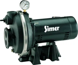
1. Install the control valve and pressure gauge in the pump body (see
Figure 7).
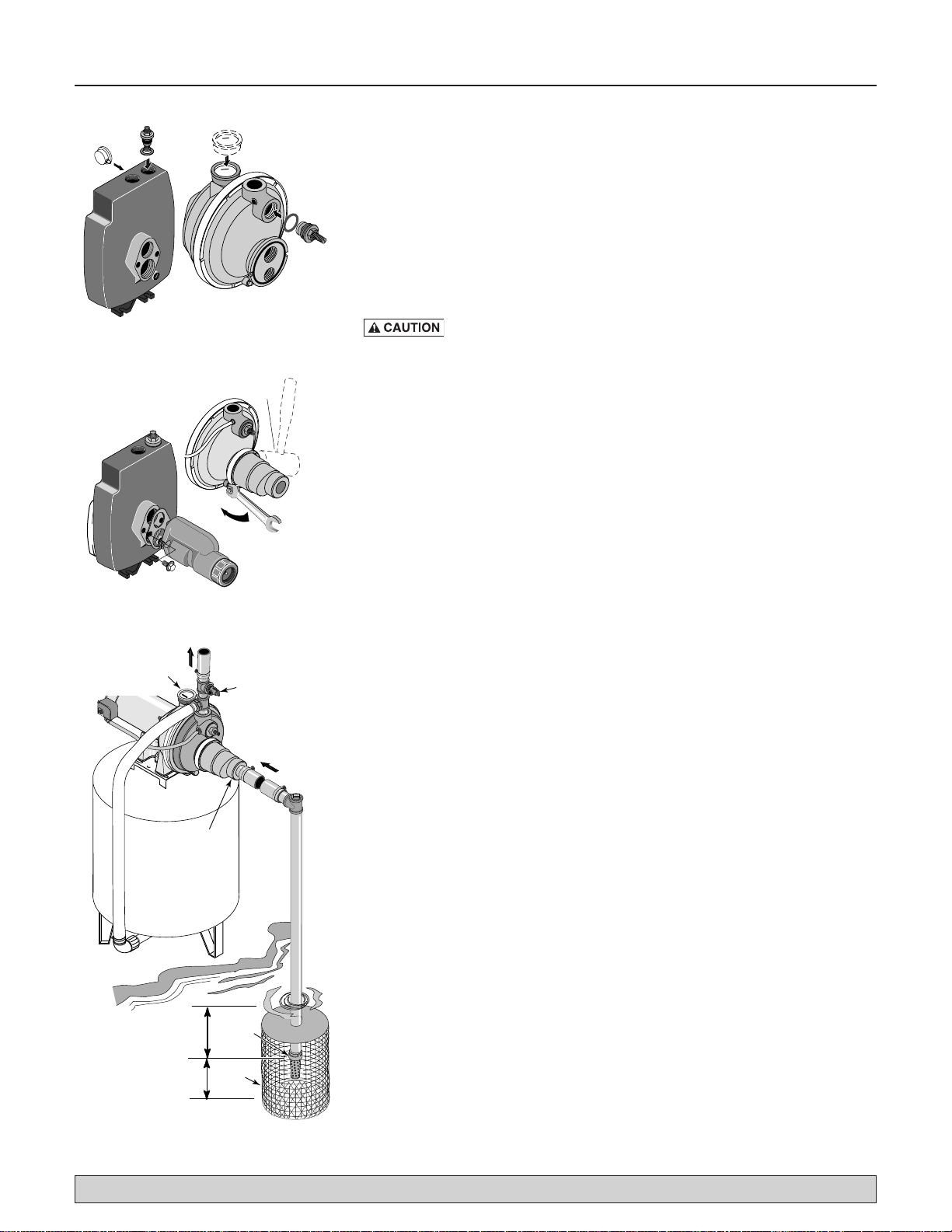
2. Install ejector kit FP4855 or kit FP4875 (kits are sold separately). Follow
the instructions provided with the kit. Align the venturi with the top
hole on the front of the pump (see Figure 8).
3. The pump should be installed as close to the water as possible, with
the fewest possible fittings (especially elbows) in the suction pipe. The
suction pipe should be at least as large as the suction port on thepump.
4. Assemble a foot valve and suction pipe (see Figure 9). Make sure that
the foot valve works freely. Use Teflon™ tape or a Teflon™-based
pipe joint compound on threaded pipe joints. Protect the foot valve
assembly from fish, trash, etc, by installing a screen around it (see
Figure 9).
5. Lower the pipe into the water until the strainer is five feet above the
bottom. It should also be at least 10 feet below the water level in order
to prevent the pump from sucking air.
6. Install a priming tee, priming plug, and suction pipe to the pump (see
Figure 9). Support the pipe so that there are no dips or sags in the pipe,
so it doesn’t strain the pump body, and so that it slopes slightly upward
from the well to the pump (high spots can cause air pockets which can
air lock the pump). Seal the suction pipe joints with Teflon™ tape or
a Teflon™ based pipe joint compound. Joints must be air- and water-
tight. If the suction pipe can suck air, the pump cannot pull water from
thewell.
You have just completed the plumbing for your new shallow well jet pump.
Please go to Page 8 for discharge pipe and tank connections.
Tap clamp
to seat it
To Household
Water System
Suction Pipe
From Well
Foot
Valve
Screen
Pressure Gauge
and Priming Port
Built-in
Check
Valve
Not
to
Scale
At least
10'
5 to 10'
Relief Valve
Figure 7: Install Control Valve and
Pressure Gauge
Figure 8: Install Ejector
Figure 9: Surface Water Installation
Loading ...
Loading ...
Loading ...