
Safety Instructions ........... 2–4
Operating Instructions
Controls ...........................5–8
Cycle Options ....................9, 10
Smart Appliance ....................13
Dryer Features ..................10, 11
Quick Start Guide ....................5
Settings Option ......................10
Using the Dryer .....................11
Installation Instructions
Before You Begin ................14, 15
Connecting the Inlet Hoses .........17
Connecting a Gas Dryer .........18–21
Connecting an
Electric Dryer ....................22–24
Exhausting the Dryer ............25–31
Final Setup ..........................32
Installing the Pedestal ...........43–45
Location of your Dryer ..........15, 16
Reversing the Door Swing .......33–39
Stacking the Washer
and Dryer .......................40–42
Troubleshooting Tips .......46–49
Consumer Support
Consumer Support ........ Back Cover
Warranty (Canada) ................. 51
Warranty (U.S.) ..................... 50
GEAppliances.com
Dryers
234D2010P001 49-90472 03-13 GE
Profile
Write the model and serial
numbers here:
Model # ______________
Serial # _______________
They are on the label on the front
of the dryer behind the door.
Owner’s Manual &
Installation Instructions
Sécheuses
Profile
Secadoras
Profile
Manuel d’utilisation et
d’installation
Manual del propietario e
instalación
La section française commence à la page 52
La sección en español empieza en la página 104
PFDS450
PFDS455
PFDN440
PFDN445
PFMS450
PFMS455
PFMN440
PFMN445
SAVE THESE INSTRUCTIONS
Printed in Mexico
Properly ground dryer to conform with all governing
codes and ordinances. Follow details in Installation
Instructions.
Install or store where it will not be exposed to
temperatures below freezing or exposed to water or
weather.
Connect to a properly rated, protected and sized
power supply circuit to avoid electrical overload.
Remove all sharp packing items and dispose of all
shipping materials properly.
Exhaust/Ducting
1
Dryers MUST be exhausted to the outside to prevent
large amounts of moisture and lint from being blown
into the room.
2
Use only rigid metal 4” diameter ductwork inside the
dryer cabinet. Use only UL approved rigid metal or
flexible metal 4-in diameter ductwork for exhausting
to the outdoors. Never use plastic or other
combustible, easy-to-puncture ductwork. USE OF
PLASTIC OR OTHER COMBUSTIBLE DUCTWORK CAN
CAUSE A FIRE. PUNCTURED DUCTWORK CAN CAUSE
A FIRE IF IT COLLAPSES OR BECOMES OTHERWISE
RESTRICTED IN USE OR DURING INSTALLATION.
For complete details, follow the Installation Instructions.
IMPORTANT SAFETY INFORMATION.
READ ALL INSTRUCTIONS BEFORE USING.
WARNING!
For your safety, the information in this manual must be followed to minimize the risk
of fire or explosion, electric shock, or to prevent property damage, personal injury, or
death.
WHAT TO DO IF YOU SMELL GAS:
1
Do not try to light a match, or cigarette,
or turn on any gas or electrical
appliance.
2
Do not touch any electrical switch; do
not use any phone in your building.
3
Clear the room, building or area of all
occupants.
4
Immediately call your gas supplier
from a neighbor’s phone. Follow the
gas supplier’s instructions carefully.
5
If you cannot reach your gas supplier,
call the fire department.
California Safe Drinking Water and Toxic Enforcement Act
This act requires the governor of California to publish a list of substances known to the state to cause cancer,
birth defects or other reproductive harm and requires businesses to warn customers of potential exposure to
such substances.
Gas appliances can cause minor exposure to four of these substances, namely benzene, carbon monoxide,
formaldehyde and soot, caused primarily by the incomplete combustion of natural gas or LP fuels.
Properly adjusted dryers will minimize incomplete combustion. Exposure to these substances can be minimized
further by properly venting the dryer to the outdoors.
PROPER INSTALLATION
This dryer must be properly installed and located in accordance with the Installation Instructions
before it is used. Installation Instructions are included in the back of this manual.
Do not store or use gasoline or other
flammable vapors and liquids in the
vicinity of this or any other appliance.
Installation and service must be
performed by a qualified installer,
service agency or the gas supplier.
2
3
WARNING!
YOUR LAUNDRY AREA
Keep the area underneath and around your
appliances free of combustible materials, (lint, paper,
rags, etc.), gasoline, chemicals and other flammable
vapors and liquids.
Keep the floor around your appliances clean and dry
to reduce the possibility of slipping.
Close supervision is necessary if this appliance is
used by or near children. Do not allow children to play
on, with or inside this or any other appliance.
Keep the area around the exhaust opening
and adjacent surrounding areas free from the
accumulation of lint, dust and dirt.
Keep all laundry aids (such as detergents, bleaches,
etc.) out of the reach of children, preferably in a
locked cabinet. Observe all warnings on container
labels to avoid injury.
Never climb on or stand on the dryer top.
WHEN USING YOUR DRYER
Never reach into the dryer while the drum is moving.
Before loading, unloading or adding clothes, wait until
the drum has completely stopped.
Clean the lint filter before each load to prevent lint
accumulation inside the dryer or in the room. DO NOT
OPERATE THE DRYER WITHOUT THE LINT FILTER IN
PLACE.
Do not wash or dry articles that have been cleaned in,
washed in, soaked in or spotted with combustible or
explosive substances (such as wax, oil, paint, gasoline,
degreasers, dry-cleaning solvents, kerosene, etc.).
These substances give off vapors that may ignite or
explode. Do not add these substances to the wash
water. Do not use or place these substances around
your washer or dryer during operation.
Do not place items exposed to cooking oils in your
dryer. Items contaminated with cooking oils may
contribute to a chemical reaction that could cause a
clothes load to catch fire.
Any article on which you have used a cleaning
solvent or that contains flammable materials (such
as cleaning cloths, mops, towels used in beauty
salons, restaurants or barber shops, etc.) must not
be placed in or near the dryer until solvents or
flammable materials have been removed. There are
many highly flammable items used in homes such
as acetone, denatured alcohol, gasoline, kerosene,
some household cleaners, some spot removers,
turpentines, waxes, wax removers and products
containing petroleum distillates.
The laundry process can reduce the flame retardancy
of fabrics. To avoid such a result, carefully follow the
garment manufacturer’s care instructions.
Do not dry articles containing rubber, plastic or
similar materials such as padded bras, tennis
shoes, galoshes, bath mats, rugs, bibs, baby pants,
plastic bags, pillows, etc. that may melt or burn.
Some rubber materials, when heated, can under
certain circumstances produce fire by spontaneous
combustion.
Do not store plastic, paper or clothing that may burn
or melt on top of the dryer during operation.
Garments labeled Dry Away from Heat or Do Not
Tumble Dry (such as life jackets containing Kapok)
must not be put in your dryer.
Do not dry fiberglass articles in your dryer. Skin
irritation could result from the remaining particles
that may be picked up by clothing during subsequent
dryer uses.
To minimize the possibility of electric shock, unplug
this appliance from the power supply or disconnect
the dryer at the household distribution panel by
removing the fuse or switching off the circuit breaker
before attempting any maintenance or cleaning
(except the removal and cleaning of the lint filter).
NOTE: Pressing START/PAUSE or POWER does NOT
disconnect the appliance from the power supply.
If you see water on the floor around the dryer, call for
service.
Do not obstruct the flow of ventilating air. Do not
stack or place laundry or throw rugs against the front
or back of the dryer.
IMPORTANT SAFETY INFORMATION.
READ ALL INSTRUCTIONS BEFORE USING. GEAppliances.com
WHEN NOT USING YOUR DRYER
Grasp the plug firmly when disconnecting this
appliance to avoid damage to the cord while pulling.
Place the cord away from traffic areas so it will not be
stepped on, tripped over or subjected to damage.
Do not attempt to repair or replace any part of this
appliance or attempt any servicing unless specifically
recommended in this Owner’s Manual or in published
user-repair instructions that you understand and have
the skills to carry out.
Before discarding a dryer, or removing it from service,
remove the dryer door to prevent children from hiding
inside.
Do not tamper with controls.
READ AND FOLLOW THIS SAFETY INFORMATION CAREFULLY.
SAVE THESE INSTRUCTIONS
WARNING!
WHEN USING YOUR DRYER (cont.)
Never attempt to operate this appliance if it is damaged,
malfunctioning, partially disassembled, or has missing
or broken parts, including a damaged cord or plug.
The interior of the machine and the exhaust duct
connection inside the dryer should be cleaned at least
once a year by a qualified technician. See the Sorting
and Loading Hints section on page 12.
If yours is a gas dryer, it is equipped with an
automatic electric ignition and does not have
a pilot light. DO NOT ATTEMPT TO LIGHT WITH A
MATCH. Burns may result from having your hand in
the vicinity of the burner when the automatic ignition
turns on.
Do not open the dryer door during steam cycles. The
steam is very hot and it will continue to exhaust from
the port for several seconds after opening. Do not
touch the steam port after a steam cycle.
Do not use a steam cycle with items such as wool,
leather, silk, lingerie, foam products or electric blankets.
Do not use steam cycles on new clothes without first
washing.
You may wish to soften your laundered fabrics or
reduce the static electricity in them by using a dryer-
applied fabric softener or an anti-static conditioner.
We recommend you use either a fabric softener
in the wash cycle, according to the manufacturer’s
instructions for those products, or try a dryer-added
product for which the manufacturer gives written
assurance on the package that their product can
be safely used in your dryer. Service or performance
problems caused by use of these products are the
responsibility of the manufacturers of those products
and are not covered under the warranty of this
appliance.
Never attempt to use the Steam Dewrinkle or Steam
Refresh cycles without clothes in the drum. Additionally,
it is highly recommended to select the appropriate
load size for best results. Selecting large load cycles
for small loads may result in wetting of clothes, and
selecting small load cycles for large loads may result
in poor dewrinkling performance.
Do not spray any type of aerosol into, on, or near dryer
at any trime. Do not use any type of spray cleaner
when cleaning dryer interior. Hazardous fumes or
electrical shock could occur.
IMPORTANT SAFETY INFORMATION.
READ ALL INSTRUCTIONS BEFORE USING.
4
5
WARNING! To reduce the risk of fire, electric shock, or injury to persons, read the IMPORTANT
SAFETY INSTRUCTIONS before operating this appliance.
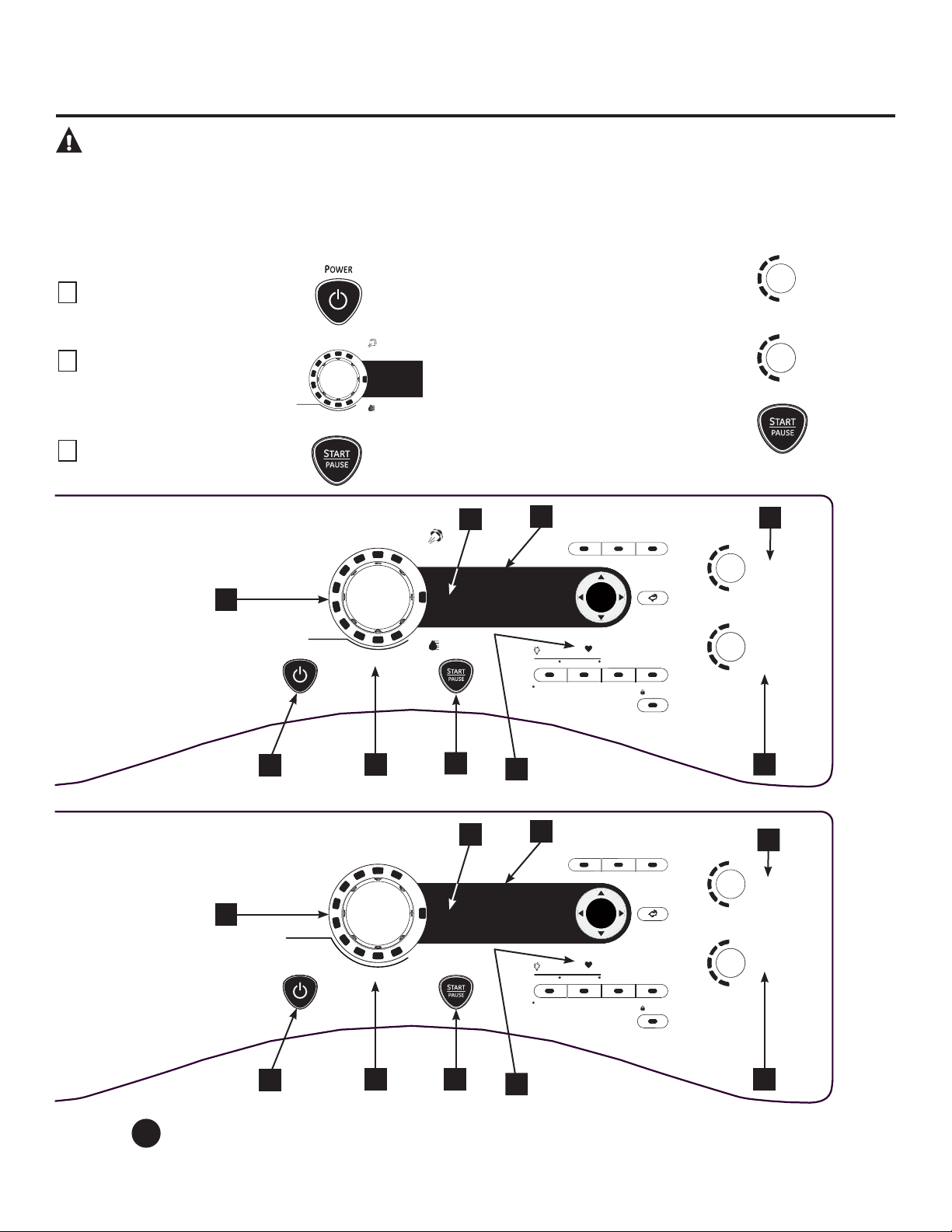
About the dryer control panel.
GEAppliances.com
Throughout this manual, features and appearance may vary from your model.
Quick Start
S
TEAM
R
EFRESH
S
PEED
D
RY
W
ARM
U
P
A
CTIVE
W
EAR
W
RINKLE
F
REE
D
ELICATES
N
ORMAL /
M
IXED
L
OADS
SENSOR DRY
TIME DRY
C
OTTONS
SPECIALTY
CYCLES
T
IMED
D
RY
S
TEAM
D
EWRINKLE
HIGH
MEDIUM
LOW
EXTRA LOW
ANTI -
BACTERIAL
DRY
TEMP
SENSOR
DRY
M
ORE DRY
DRY
LESS DRY
DAMP
EXTRA DRY
If the screen is dark, press the POWER button to “wake up”
the display.
1
Press the
POWER
button.
2
Select a cycle by turning the
Cycle Knob.
3
If you selected a SENSOR CYCLE –
just press the START/PAUSE button.
If you selected a TIME DRY CYCLE
-select your heat setting and the
amount of time you want your items
to dry by using the cursor buttons.
Then press the START/PAUSE button.
ENTER
HIGH
MEDIUM
LOW
EXTRA LOW
ANTI -
BACTERIAL
DRY
TEMP
SENSOR
DRY
MORE DRY
DRY
LESS DRY
DAMP
EXTRA DRY
POWER
DELAY
S
TAR T
Push to Lock Control
Hold 3 Secs to Unlock
e
DRY
DRYER
RACK
LOCK
BACKBACK
SPECIALTY
CYCLES
PRESS & HOLD 3 seconds for secondary OPTIONS
STORE MY CYCLE
EXTENDED
TUMBLE
DRUM
LIGHT
SETTINGS
MY
CYCLE
DAMP
ALERT
STEAMREFRESH
SPEED DRY
WARM UP
ACTIVE WEAR
WRINKLE FREE
DELICATES
NORMAL /
MIXED LOADS
SENSOR DRY
TIME DRY
TIMED DRY
STEAM
DEWRINKLE
COTTONS
1
2
3
6
7
8
9
ENTER
HIGH
MEDIUM
LOW
EXTRA LOW
ANTI -
BACTERIAL
DRY
TEMP
SENSOR
DRY
MORE DRY
DRY
LESS DRY
DAMP
EXTRA DRY
POWER
DELAY
STAR T
Push to Lock Control
Hold 3 Secs to Unlock
e
DRY
DRYER
RACK
LOCK
BACKBACK
SPECIALTY
CYCLES
PRESS & HOLD 3 seconds for secondary OPTIONS
STORE MY CYCLE
EXTENDED
TUMBLE
DRUM
LIGHT
SETTINGS
MY
CYCLE
DAMP
ALERT
SPEED DRY
ACTIVE WEAR
WRINKLE FREE
DELICATES
NORMAL /
MIXED LOADS
COTTONS
SENSOR DRY
TIME DRY
DEWRINKLE
WARM UP
TIMED DRY
AIR FLUFF
NO HEAT
1
2
3
7
8
9
Models: PFDS450 / PFDS455 / PFMS450 / PFMS455
Models: PFDN440 / PFDN445 / PFMN440 / PFMN445
Power
Press to “wake up” the display. If the display is active, press to turn the dryer off.
NOTE: Pressing POWER does not disconnect the appliance from the power supply.
1
6
5
5
4
4
About the dryer control panel.
Dry Cycles
The dry cycle controls the cycle time for the drying process. The chart below will help you match the dry setting with the
loads.
Sensor Cycles
COTTONS For cottons and most linens.
NORMAL/ For loads consisting of cottons and poly-blends.
MIXED LOAD
WRINKLE FREE For wrinkle-free/easy care and permanent press items.
ACTIVE WEAR Clothing worn for active sports exercise and some casual wear. Fabrics include new
technology finishes and stretch fibers such as Spandex.
DELICATES For lingerie and special-care fabrics.
SPEED DRY For small loads that are needed in a hurry, such as sports or school uniforms. Can also be
used if the previous cycle left some items damp, such as collars or waistbands.
Timed Dry Cycles
STEAM For slightly wrinkled dry garments. Significantly reduces wrinkles on 1–5 garments.
REFRESH Selecting a higher number of garments for the cycle (e.g., selecting 5-garment load for a 1-garment load) may result in excessive wetting
of clothes. After the STEAM REFRESH Cycle, the unit will beep and display “Garments Ready” and “0:00.” If the unit is not turned off or if the
door is not opened, the dryer will continue to tumble for 30 minutes. At the end of 30 minutes, it will display “0:00” and “Cycle Complete.”
NOTE: When STEAM REFRESH is selected, “EXTENDED TUMBLE” will automatically turn on and cannot be turned off.
A single extremely light fabric item may need to have an additional item included in the steam refresh cycle to achieve optimum results.
DEWRINKLE For removing wrinkles from items that are dry or slightly damp. This cycle is not reccomended for delicate
(on some models) fabrics.
STEAM For use with larger loads than STEAM REFRESH. Ideal for loads left in dryer for an extended
DEWRINKLE time. Selecting a larger cycle than needed (e.g., selecting Large Load for a half-full dryer)
(on some models) may result in excessive wetting of clothes.
WARM UP Provides 10 minutes of warming time to warm up clothes.
My Cycle (on some models)
MY CYCLE Press to use, create or modify custom dry cycles.
Timed Dry
Use to set your own dry time. TIMED DRY is also recommended for small loads.
To use TIMED DRY:
1. Turn dry cycle dial to TIMED DRY.
2. Select the drying time by pressing the S and T buttons. You can increase the time in 10-minute increments up to 2 hours, 5 minutes.
3. Select the DRY TEMP.
4. Close the door.
5. Press START/PAUSE.
Sensor Dry
The sensor continuously monitors the amount of moisture in the load. When the moisture in your clothes reaches your selected dry level, the dryer will stop.
EXTRA DRY Use for heavy-duty fabrics or items that should be very dry, such as towels.
MORE DRY Use for heavy or mixed type of fabrics.
DRY Use for normal dryness level suitable for most loads. This is the preferred cycle
for energy saving.
LESS DRY Use for lighter fabric (ideal for ironing).
DAMP For leaving items partially damp.
4
(on some models)
6
2
3
7
GEAppliances.com
Dry Temp
You can change the temperature of your dry cycle.
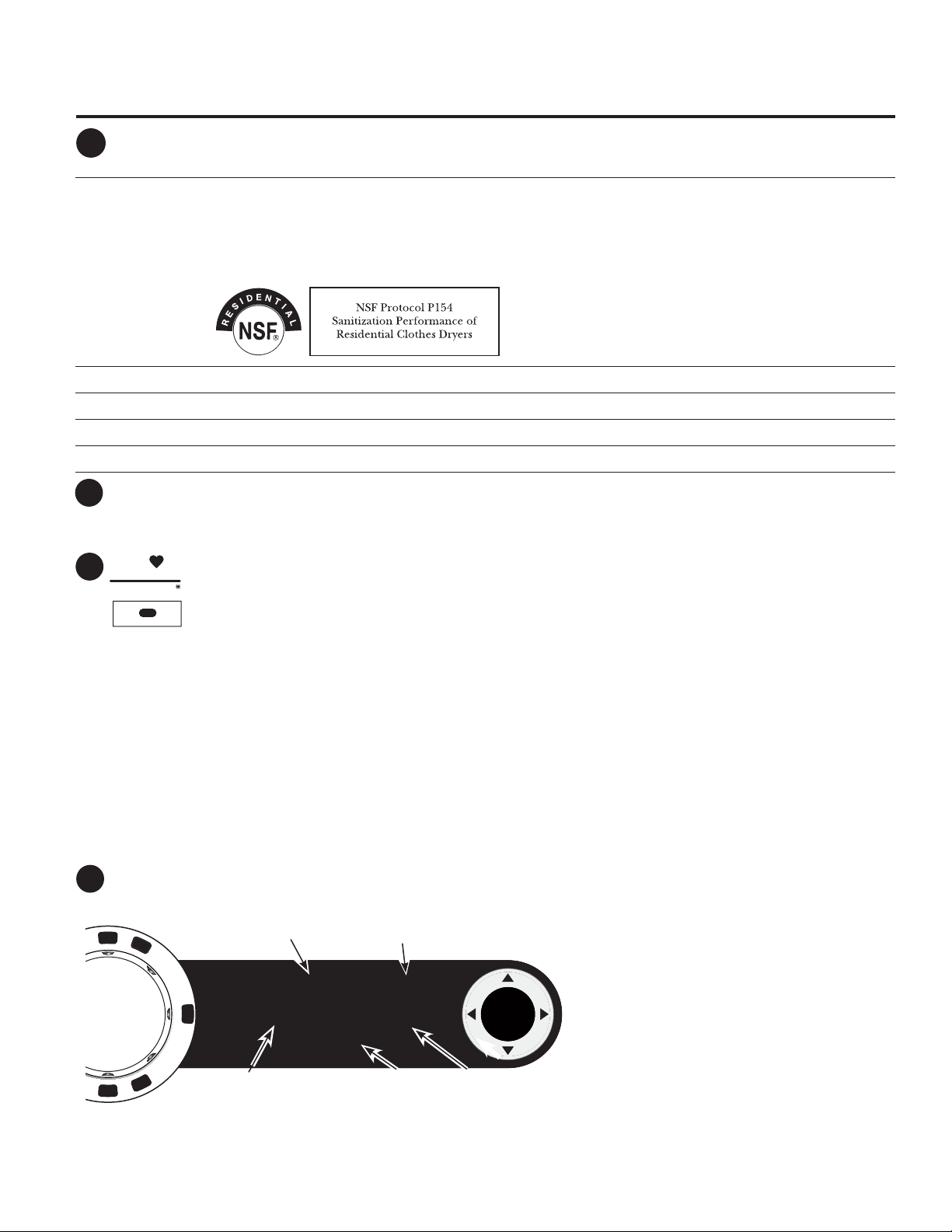
ANTI-BACTERIAL This option may only be used with COTTONS or MIXED LOAD cycles. This option reduces certain types of bacteria by
99.9%, including: Staphylococcus aureus, Pseudomonas aeruginosa and Klebsiella pneumoniae*. The anti-bacterial
process occurs when high heat is used during a portion of this drying cycle.
NOTE: Do not use this cycle on delicate fabrics.
* The Anti-Bacterial Cycle is Certified by NSF International (formerly National Sanitation Foundation) to NSF Protocol
P154 Sanitization Performance of Residential Clothes Dryers.
HIGH For regular to heavy cottons.
MEDIUM For synthetics, blends and items labeled permanent press.
LOW For delicates, synthetics and items labeled Tumble Dry Low.
EXTRA LOW For lingerie and special-care fabrics.
START/PAUSE
Press to start a dry cycle. If the dryer is running, press it once and it will pause the dryer. Press it again to resume the dry
cycle.
My Cycle (on some models)
Set up your favorite combination of settings and save them here for one touch recall. These custom
settings can be set while a cycle is in progress.
To store a MY CYCLE combination of settings:
1. Select your drying cycle.
2. Change DRY TEMP and SENSOR DRY settings to fit your needs.
3. Select any drying OPTIONS you want.
4. Press and hold the MY CYCLE button for 3 seconds to store your selection. A beep will sound the button will light up, and
the unit will display “My cycle is now programed with the current cycle settings”.
To recall your stored MY CYCLE combination:
Press the MY CYCLE button before drying a load. The light in the center of the button will light up when MY CYCLE is selected.
To change your stored MY CYCLE combination:
Follow Steps 1–4 in “To store a MY CYCLE combination of settings.”
Display
“CLEAN LINT FILTER” (message)
This message appears periodically. It is only a reminder.
5
ENTER
SPECIALTY
CYCLES
SPECIALTY CYCLE 1:10
Comforters
Delay Time 1:00
Clean Lint Filter
0
Special Cycle Status OR
Dryer Rack OR Timed Dry
Est. Cycle Time
OR Time to Dry
Delay Time
Status
Lint Filter Status
Screen
DELAY TIME
STORE MY CYCLE
MY
CYCLE
After the POWER button is pressed, the CLEAN
LINT FILTER message could appear if the
previous cycle was not finished. This message
will disappear after the START button is pressed.
Even though you have already cleaned the
filter (before the POWER button was pressed),
the CLEAN LINT FILTER message will still be
displayed until the START button is activated.
6
7
8

About the dryer control panel.
Specialty Cycles
1. Turn the CYCLE knob to SPECIALTY CYCLES. A list of cycle options will appear in the display.
2. Using the cursor buttons, select a CATEGORY.
3. Using the cursor buttons, select a CYCLE.
Press the BACK button to take you back to the CATEGORIES.
4. Press ENTER to select.
5. Press the START/PAUSE button.
SPECIALTY CYCLES include:
Garment
Coats
Hosiery/Bras (use mesh bag)
Jeans
Khakis
Bed and Bath
Blankets (Cotton)
Comforters
Sheets
Towels
Specialty Cycles
Air Fluff
Dryel
Fleece
Fragile Cottons
Performance Fabrics
Pet Bedding
Play Clothes
Rack Dry
Sleeping Bag
Throw Rugs
9
Washer Communicated Cycles
To turn on communication, press the SETTINGS button
on the washer control panel. When “DRYER LINK”
appears in the display, press ENTER. Using the arrow
keys, select ON; then press ENTER.
When the washer cycle is completed, the washer will
communicate with the dryer when any button on the
control panel is touched or the door is opened.
The washer will display, “TRANSFERRING CYCLE
INFORMATION TO THE DRYER” and the dryer will
display, “RECEIVING CYCLE INFORMATION TO THE
DRYER”.
The dryer will only communicate with the washer if
the dryer is not running a cycle.
If the washer starts a new cycle before the dryer has
a chance to communicate with it, the information will
be lost.
8
9
About cycle options.
NOTE: Not all features are available on all dryer models.
GEAppliances.com
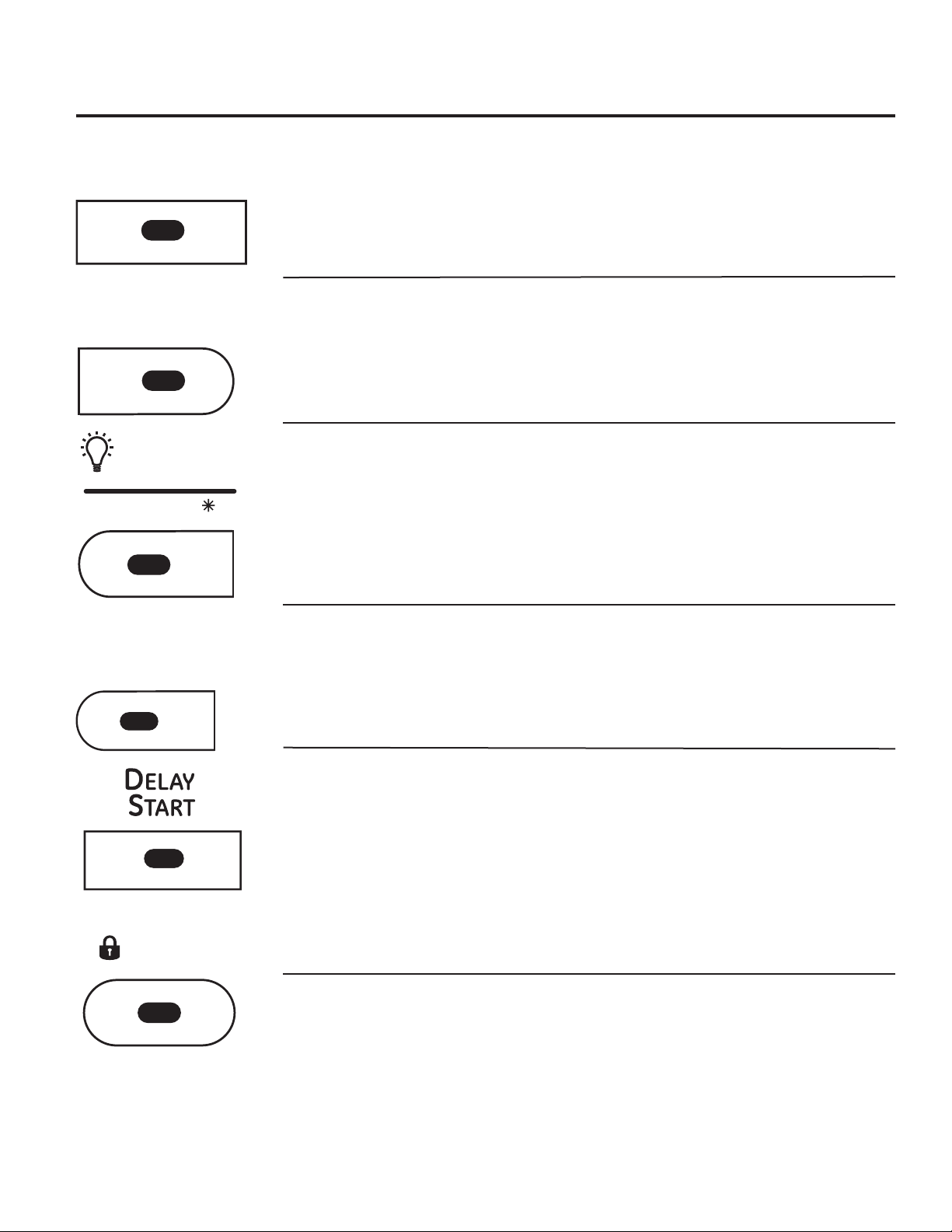
Extended Tumble
Minimizes wrinkles by adding approximately 60
minutes of no-heat tumbling after clothes are
dry.
The light in center of the button will light up
when EXTENDED TUMBLE is on.
Extended Tumble is automatically selected for the
SteamRefresh cycle and cannot be deselected.
Dryer will beep and display “Garments Ready”
when SteamRefresh is complete. The dryer will
continue in Extended Tumble until the door is
opened.
Damp Alert
This option causes the dryer to beep when
clothes have dried to a damp level. Remove
items that you wish to hang dry. The DAMP
ALERT will only beep when this option is selected.
Removing clothes and hanging them when they
are damp can reduce the need to iron some
items.
The light in center of the button will light up
when DAMP ALERT is on.
Drum Light
Press this button to turn on the light in the dryer.
Press the button again to turn the light off.
This only controls the light when the door is shut.
NOTE: The light will turn off by itself after one
minute when the door is shut.
When the door is opened, the light comes on
automatically.
The light in center of the button will light up
when DRUM LIGHT is on.
NOTE: Hold down the DRUM LIGHT button for
3 seconds to access the SETTINGS menu. (See
page 10 for more details)
Delay Start
Use to delay the start of your dryer.
1. Choose your dry cycle and any options.
2. Press DELAY START. You can change the
delay time in 1/2-hour increments, using the
S or T arrow pads.
3. Press the START/PAUSE button to start the
countdown.
The countdown time will be shown in the
ESTIMATED TIME REMAINING display.
NOTES:
If the door is opened while the dryer is
in DELAY, the countdown time will not
restart unless the door is closed and
START/PAUSE button has been pressed
again.
You can delay the start of a dry cycle up
to 24 hours.
The light in center of the button will light up
when DELAY START is on.
e-Dry
Reduces the total energy consumption of
specific dryer cycles by adjusting certain heat
settings.
NOTE: Cycle times will change when e-DRY is
selected
This cycle can be used with DELICATES, ACTIVE
WEAR, EASY CARE, NORMAL/MIXED LOADS
and COTTONS.
EXTENDED
TUMBLE
D
AMP
ALERT
e
DRY
Lock
You can lock the controls to prevent any
selections from being made. Or you can lock
the controls after you have started a cycle.
Children cannot accidentally start the dryer by
touching pads with this option selected.
To lock the dryer, press the LOCK button. To
unlock the dryer, press and hold the LOCK
button for 3 seconds.
The light in center of the LOCK button will light
up when the controls are locked.
Even though the controls are locked, the POWER
button is still active in case you have to turn the
unit off.
Push to Lock Control
Hold 3 Secs to Unlock
LOCK
DRUM
LIGHT
SETTINGS
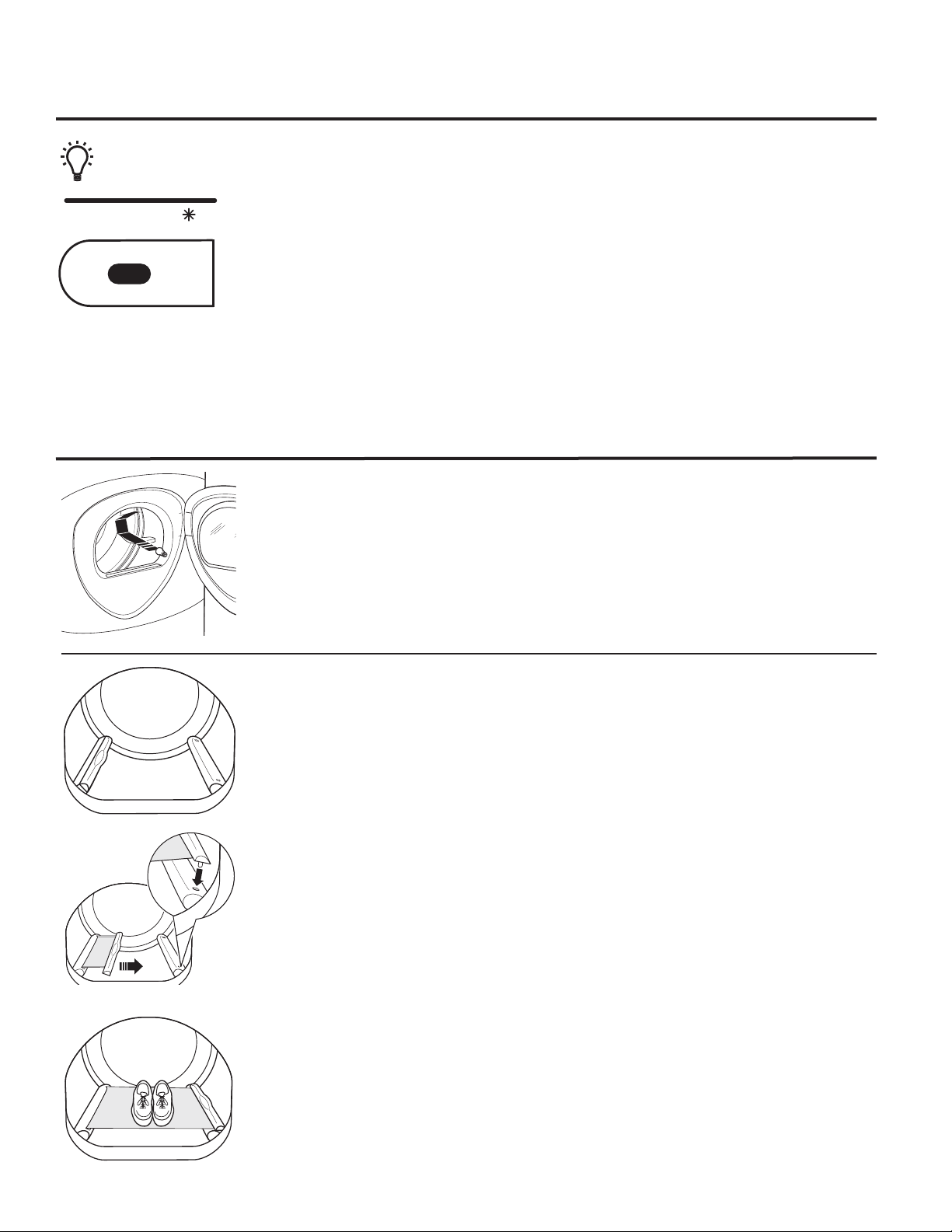
Built-In Rack Dry System
A handy drying rack may be used for drying items such as tennis shoes. Place items flat on the
drying rack and block such items as wool sweaters and delicate fabrics. Dry with low heat.
To install the Built-In Rack Dry System
1. Make sure the drum of the dryer is oriented so the rack drying system is on the left side of the
dryer.
2. Pull the drying rack screen out from the left side and engage the handle “posts” in the
opposite baffle slots.
3. Place the garment on the rack and close the door.
4. Press the DRYER RACK button.
5. Select desired time.
6. Press the START/PAUSE button.
NOTE:
Do not use this drying rack when there are other clothes in the dryer.
Make sure to detach the drying rack at the end of the cycle and fully retract the screen back
into the baffle.
Engage the handle posts
Settings
Under the SETTINGS option, you can
adjust the volume or the brightness of
the display.
VOLUME
End of Cycle (signal) volume can be set from
HIGH, MED, LOW or OFF.
Control Sounds volume can be set from
HIGH, MED, LOW or OFF.
DISPLAY BRIGHTNESS can be set from HIGH,
MED or LOW.
After you have made your selection, press
ENTER.
NOTE: To access the SETTINGS menu, hold
down the DRUM LIGHT button for 3 seconds.
About dryer features.
Drum Lamp
Before replacing the light bulb, be sure to unplug the dryer power cord or disconnect the dryer at
the household distribution panel by removing the fuse or switching off the circuit breaker. Reach
above dryer
opening from inside the drum. Remove the
bulb and replace with the same size bulb.
About cycle options.
NOTE: Not all features are available on all dryer models.
DRUM
LIGHT
SETTINGS
Press & hold for 3
seconds for secondary
options
10
11
About dryer features (cont.).
GEAppliances.com
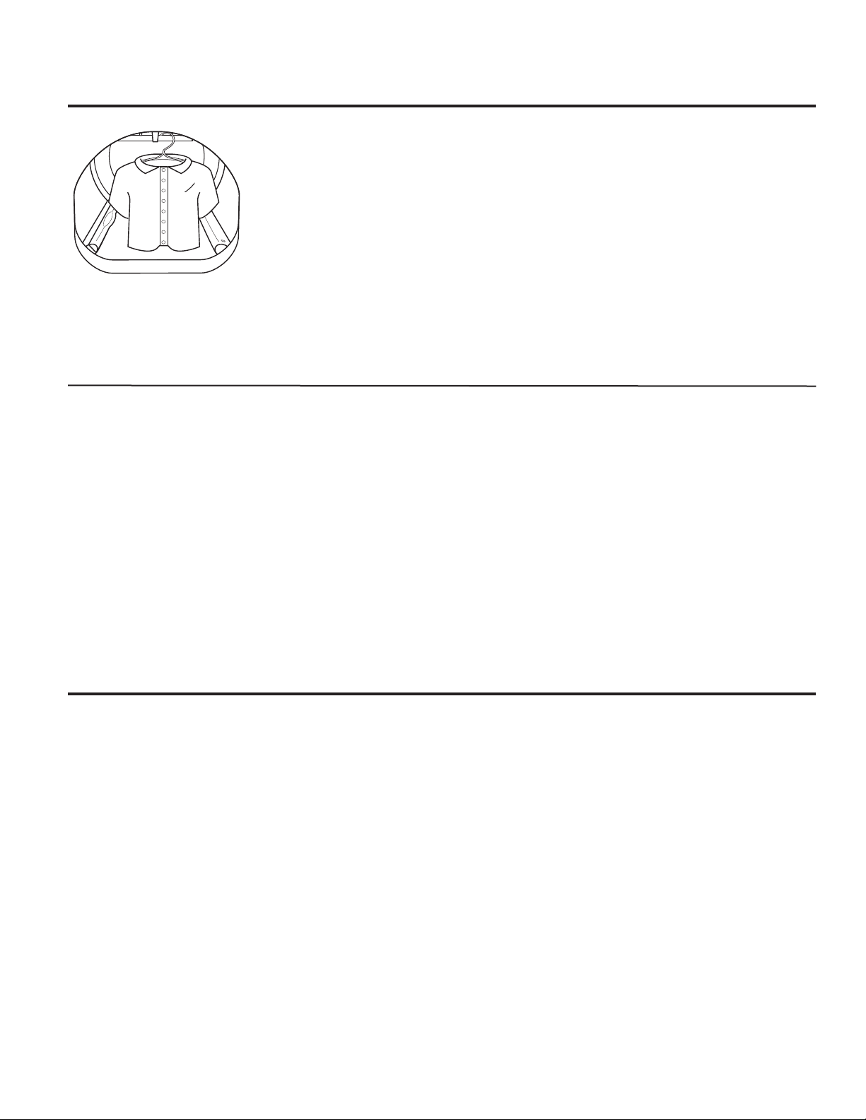
To Use the Built-In Hook for
Hanging Garments
1. Make sure the drum of the dryer is
oriented so the hook is on the top
center of the dryer.
2. Using your finger, pull the hook out of
the baffle.
3. Hang the garment on a hanger, hang
the hanger on the hook and close the
door.
4. Press the DRYER RACK button.
5. Select the desired time.
6. Press the START/PAUSE button.
Reverse Tumble
™
All Profile front-load matching dryers are equipped with the Reverse Tumble
™
feature,
as part of the Duo Dry Plus system
™
. By reversing the direction of drum rotation during
the drying cycle, your dryer will tangle the clothes load less, dry more evenly and
improve drying times. Typical loads such as bed and bath mixed loads, where sheets,
towels and pillow cases are laundered together, benefit from this capability. When
the dryer reverses direction, there will be a slight pause and sound change. This is
normal. All dryer cycles utilize this feature, except when the rack dry option is selected,
in which case the drum does not tumble.
Using the dryer.
Always follow fabric manufacturer’s care label when laundering.
Sorting and Loading Hints
As a general rule, if clothes are sorted
properly for the washer, they are sorted
properly for the dryer. Try also to sort items
according to size. For example, do not dry a
sheet with socks or other small items.
Do not add fabric softener sheets once
the load has become warm. They may
cause fabric softener stains. Bounce
®
Fabric Conditioner Dryer Sheets have been
approved for use in this dryer when used
in accordance with the manufacturer’s
instructions.
See below for lint filter cleaning instructions.
Do not overload. This wastes energy and
causes wrinkling.
Do not dry the following items: fiberglass
items, woolens, rubber-coated items, plastics,
items with plastic trim and foam-filled items.
Using the dryer.
Care and Cleaning of the Dryer
Dryer Interior and Duct: The interior of
the appliance and exhaust duct should be
cleaned once a year by qualified service
personnel.
The Exterior: Wipe or dust any spills or
washing compounds with a damp cloth.
Dryer control panel and finishes may be
damaged by some laundry pretreatment
soil and stain remover products. Apply these
products away from the dryer. The fabric
may then be washed and dried normally.
Damage to your dryer caused by these
products is not covered by your warranty.
Do not touch the surface or the display with
sharp objects.
The Lint Filter: Clean the lint filter before
each use. Remove by pulling straight up.
Run your fingers across the filter. A waxy
buildup may form on the lint filter from
using dryer-added fabric softener sheets.
To remove this buildup, wash the lint screen
in warm, soapy water. Dry thoroughly and
replace. Do not operate the dryer without the
lint filter in place.
Vacuum the lint from the dryer lint filter if you
notice a change in dryer performance.
Stainless Steel: To clean stainless steel
surfaces, use a damp cloth with a mild,
nonabrasive cleaner suitable for stainless
steel surfaces. Remove the cleaner residue,
and then dry with a clean cloth.
The stainless steel used to make the dryer drum
provides the highest reliability available in a GE
dryer. If the dryer drum should be scratched or
dented during normal use, the drum will not rust
or corrode. These surface blemishes will not affect
the function or durability of the drum.
The Exhaust Hood: Check with a mirror that
the inside flaps of the hood move freely
when operating. Make sure that there is no
wildlife (birds, insects, etc.) nesting inside the
duct or hood.
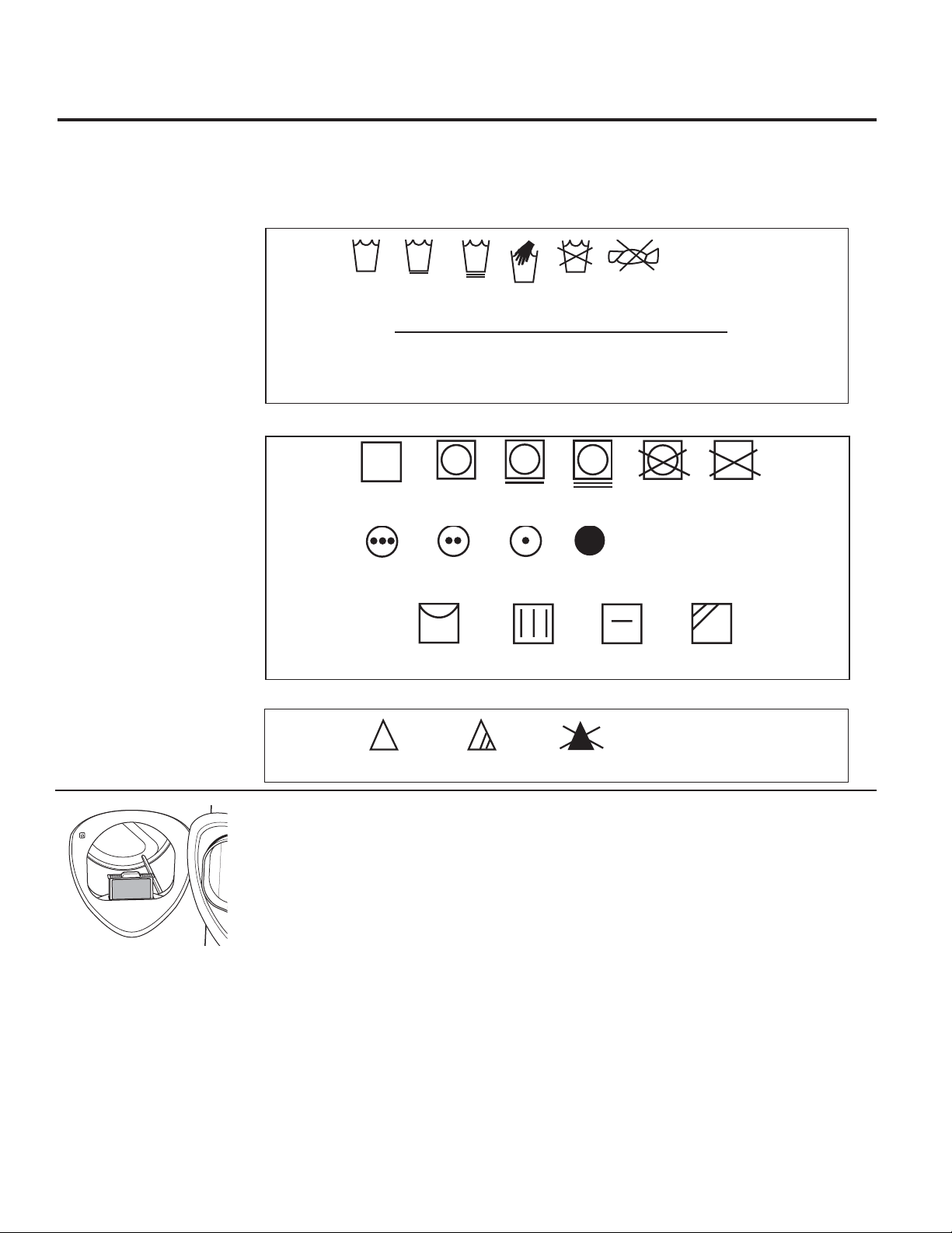
12
Tumble
dry
Dry
Normal
Permanent Press/
wrinkle resistant
Gentle/
delicate
Do not tumble dry
Do not dry
(used with
do not wash)
Heat
setting
High
Medium
Low
No heat/air
Special
instructions
Line dry/
hang to dry
Drip dry
Dry flat
In the shade
Dry Labels
Bleach Labels
Wash Labels
Fabric Care Labels
Below are fabric care label “symbols” that affect the clothing you will be laundering.
Machine
wash
cycle
Normal
Permanent Press/
wrinkle resistant
Gentle/
delicate
Hand wash
Do not wash Do not wring
Front load
target water
temperature
Target Automatic
Category Water Temperature Temperature Control
Tap Cold Inlet Water Temperature Not used
Cold 27°C/80°F Used
Warm 40°C/105°F Used
Hot 50°C/120°F Used
Sanitize 70°C/160°F Used
Bleach
symbols
Any bleach
(when needed)
Only non-chlorine bleach
(when needed)
Do not bleach
Models PFDS450, PFDS455, PFDN440, PFDN445 are compatible with the
GE Smart Appliance Module (SAM) which can be purchased separately.
Contact your local utility or visit www.GEAppliances.com/smart-appliances
to see if your area is using Demand Response (DR) technology.
Installation
The preferred location for the module installation is on top of the clothes
dryer. Details on how to connect the cables to the module are in the
instructions that come with the module.
Wait 5 minutes; then press the Settings button. Scroll and look for the
energy management screen as seen below.
This screen means the module is attached correctly and you can begin to
use your Smart Appliance following the instructions below.
If the Energy Management Screen is not available, refer to the SAM module
troubleshooting guide.
Quick Guide
There are 4 power levels available: Critical, High, Medium and Low. On the
Medium and Low levels, the unit runs as normal. The following steps show
how the unit reacts during startup at Critical and High power levels.
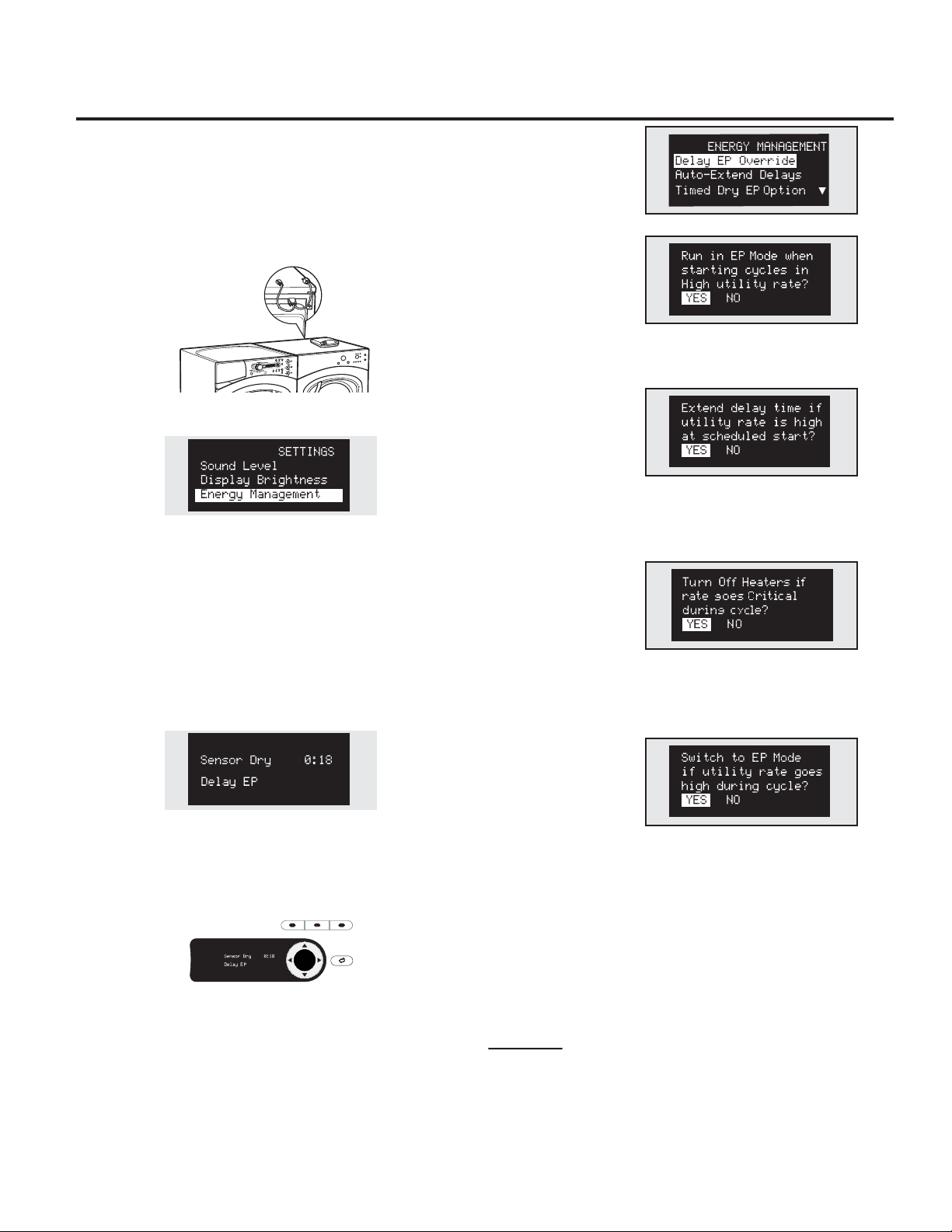
Option 1 (Delay EP)
During startups at Critical and High levels, the unit will delay
starting until the level becomes Medium or Low. Press the START/PAUSE
button.
Option 2 (Override Delay EP)
To start the unit when Delay EP is shown, press the DELAY START button to
turn the delay off. Then press START/PAUSE to begin the cycle.
During a Critical Rate period, the Critical Response Mode** will also be
activated to maximize energy savings. EP will be displayed.
Option 3 (Override “e” DRY)
After overriding the delay function, pressing the “e”DRY button will disable
the “e”DRY setting. Pressing the START/PAUSE key will begin the selected
cycle.
During a Critical Rate period, the Critical Response Mode** will be activated
to maximize energy savings. EP will be displayed.
**Note: The Critical Response Mode can be disabled at any time by
pressing and holding the “e”DRY Button for 3 seconds. EP will be removed
from the display
Settings Menu
Press SETTINGS; then select
Energy Management.
Delay EP Override
If you are starting a cycle in
a Critical or High utility rate,
this option allows the unit
to automatically run on an
EP Cycle. This setting will
operate with less energy than normal cycles. Default setting is YES.
Auto-Extend Delays
If a timed delay is selected,
this option allows for the
scheduled start to extend
if the utility rate is Critical or
High at the scheduled start. The default setting will automatically extend
these cycles.
Critical Rate Option
This option allows your smart
appliance to respond to
Critical Rate information by
automatically engaging the
Critical Response Mode. The
Critical Response Mode is designed to maximize energy savings when a
cycle is run during a Critical Rate period. The default setting is YES. Setting
this option to NO will disable the Critical Response Mode.
Timed Dry EP Option
If the unit is running in Timed
Dry Mode and the utility rate
switches to Critical or High,
the unit will conserve energy
by decreasing heat if YES (default) is selected. If NO is selected, the unit will
operate normally.
NOTE: When YES (default) is selected, your load may be damp
at the end of the cycle.
In order for the Smart Appliance features on the appliance to work,
additional equipment is required to be installed to interface with the local
utility. Such equipment may be sold separately and/or is available through
your utility as part of the pilot test program. Check with your utility company
to see if a pilot test program is available in your area and for full details.
PLEASE NOTE: If you move to an area where the program is not available,
the demand response features cannot be activated and utilized on the
appliance. The appliance will function as normal after the demand response
equipment has been deactivated or disconnected.
SMART APPLIANCE (on some models) GEAppliances.com
ENTER
DELAY
STAR T
e
DRY
DRYER
RACK
BACKBACK
13
Installation Dryer
Instructions
BEFORE YOU BEGIN
Read these instructions completely and carefully.
•
IMPORTANT – Save these instructions for local
electrical inspector’s use.
•
IMPORTANT – Observe all governing codes and
ordinances.
•
Install the clothes dryer according to the manufacturer’s
instructions and local codes.
•
Note to Installer – Be sure to leave these instructions
with the Consumer.
•
Note to Consumer – Keep these instructions for future
reference.
•
Clothes dryer installation must be performed by a
qualified installer.
•
This dryer must be exhausted to the outdoors.
•
Before the old dryer is removed from service or
discarded, remove the dryer door.
•
Service information and the wiring diagram are located
in the control console.
•
Do not allow children on or in the appliance. Close
supervision of children is necessary when the appliance
is used near children.
•
Proper installation is the responsibility of the installer.
•
Product failure due to improper installation is not
covered under the Warranty
.
• Install the dryer where the temperature is above 50°F
for satisfactory operation of the dryer control system.
• Remove and discard existing plastic or metal foil duct
and replace with UL-listed duct.
Questions? Call 800.GE.CARES (800.432.2737) or visit our Web site at: GEAppliances.com
In Canada, call 1.800.561.3344 or visit www.GEAppliances.ca
FOR YOUR SAFETY:
WARNING –
Risk of Fire
•
To reduce the risk of severe injury or death, follow all
installation instructions.
•
Clothes dryer installation must be performed by a
qualified installer.
•
Install the clothes dryer according to these
instructions and in accordance with local codes.
•
This dryer must be exhausted to the outdoors.
•
Use only rigid metal 4
”
diameter ductwork inside the
dryer cabinet and use only UL approved transition
ducting between the dryer and the home duct.
•
DO NOT install a clothes dryer with flexible plastic
ducting materials. If flexible metal (semi-rigid or
foil-type) duct is installed, it must be UL-listed and
installed in accordance with the instructions found
in “Connecting the Dryer to House Vent” on page 26
of this manual. Flexible ducting materials are known
to collapse, be easily crushed and trap lint. These
conditions will obstruct dryer airflow and increase
the risk of fire.
•
Do not install or store this appliance in any location
where it could be exposed to water and/or weather.
•
Save these instructions. (Installers: Be sure to leave
these instructions with the customer.)
FOR GAS MODELS ONLY:
NOTE: Installation and service of this dryer must be
performed by a qualified installer, service agency or
the gas supplier.
In the Commonwealth of Massachusetts:
•
This product must be installed by a licensed
plumber or gas fitter.
•
When using ball-type gas shut-off valves, they
shall be T-handle-type.
•
A flexible gas connector, when used, must not
exceed 3 feet.
CALIFORNIA SAFE DRINKING WATER AND
TOXIC ENFORCEMENT ACT
This act requires the governor of California to publish a
list of substances known to the state to cause cancer,
birth defects or other reproductive harm and requires
businesses to warn customers of potential exposure to such
substances. Gas appliances can cause minor exposure to
four of these substances, namely benzene, carbon monoxide,
formaldehyde and soot, caused primarily by the incomplete
combustion of natural gas or LP fuels. Properly adjusted
dryers will minimize incomplete combustion. Exposure to
these substances can be minimized further by properly
venting the dryer to the outdoors.
14
PFDS450 / PFDS455 /PFDN440 / PFDN445 /
PFMS450 / PFMS455 / PFMN440 / PFMN445
15
Installation Instructions
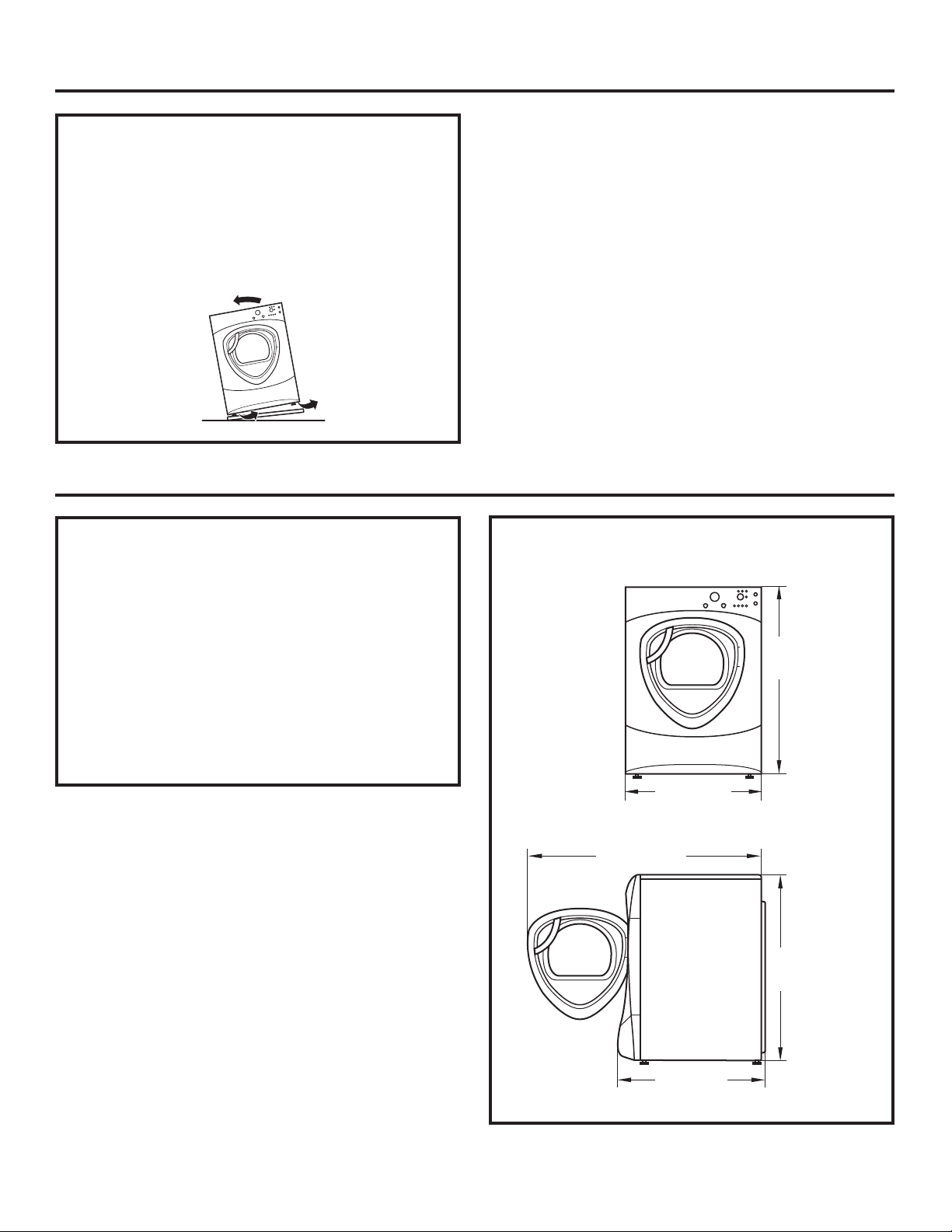
UNPACKING YOUR DRYER
Tilt the dryer sideways and remove the foam
shipping pads by pulling at the sides and breaking
them away from the dryer legs. Be sure to remove
all of the foam pieces around the legs.
Remove the bag containing the literature and serial
cable.
DRYER DIMENSIONS
51″
(129.5 cm)
39.1″
(993 cm)
32.34″
(847 cm)
27″
(68.6 cm)
39.1″
(993 cm)
27”
(68.6 cm)
39.5”
(100.3 cm)
33.5”
(85.1 cm)
39.5”
(100.3 cm)
Side View
Front View
LOCATION OF YOUR DRYER
MINIMUM CLEARANCE OTHER THAN
ALCOVE OR CLOSET INSTALLATION
Minimum clearance to combustible surfaces and for
air openings are:
•
0 inch clearance both sides
•
1 inch front
•
3 inches rear
Consideration must be given to provide adequate
clearance for proper operation and service.
53”
(134.6 cm)
Installation Instructions
REQUIREMENTS FOR ALCOVE OR
CLOSET INSTALLATION
• Your dryer is approved for installation in an
alcove or closet, as stated on a label on the dryer
back.
•
The dryer MUST be vented to the outdoors. See
the EXHAUSTING THE DRYER section.
•
Minimum clearance between dryer cabinet and
adjacent walls or other surfaces is:
0” either side
3” front and rear
•
Minimum vertical space from floor to overhead
shelves, cabinets, ceilings, etc., is 52”.
•
Closet doors must be louvered or otherwise
ventilated and have at least 60 square inches
of open area equally distributed. If the closet
contains both a washer and a dryer, doors must
contain a minimum of 120 square inches of open
area equally distributed.
•
The closet should be vented to the outdoors to
prevent gas pocketing in case of gas in the supply
line.
•
No other fuel-burning appliance shall be installed
in the same closet with the dryer (gas models
only).
NOTE: WHEN THE EXHAUST DUCT IS LOCATED AT
THE REAR OF THE DRYER, MINIMUM CLEARANCE
FROM THE WALL IS 5.5 INCHES.
BATHROOM OR BEDROOM INSTALLATION
• The dryer MUST be vented to the outdoors. See
EXHAUSTING THE DRYER.
•
The installation must conform with local codes or,
in the absence of local codes, with the NATIONAL
ELECTRICAL CODE, ANSI/NFPA NO. 70 (for electric
dryers) or NATIONAL FUEL GAS CODE, ANSI Z223
(for gas dryers).
MOBILE OR MANUFACTURED HOME
INSTALLATION
• The installation must conform to the
MANUFACTURED HOME CONSTRUCTION &
SAFETY STANDARD, TITLE 24, PART 32–80 or, when
such standard is not applicable, with AMERICAN
NATIONAL STANDARD FOR MOBILE HOME, NO.
501B.
•
The dryer MUST be vented to the outdoors with
the termination securely fastened to the mobile
home structure. (See EXHAUSTING THE DRYER.)
•
The vent MUST NOT be terminated beneath a
mobile or manufactured home.
•
The vent duct material MUST BE METAL.
•
FOR GAS MODELS ONLY: KIT 14-D346-33 MUST be
used to attach the dryer securely to the structure.
•
FOR GAS MODELS ONLY: The vent MUST NOT be
connected to any other duct, vent or chimney.
•
Do not use sheet metal screws or other refastening
devices which extend into the interior of the
exhaust vent.
•
Provide an opening with a free area of at least 25
sq. in. for introduction of outside air into the dryer
room.
16
GARAGE INSTALLATION (IF ALLOWED
BY LOCAL CODES)
• Dryers installed in garages must be elevated 18
inches (46cm) above the floor.
17
Installation Instructions
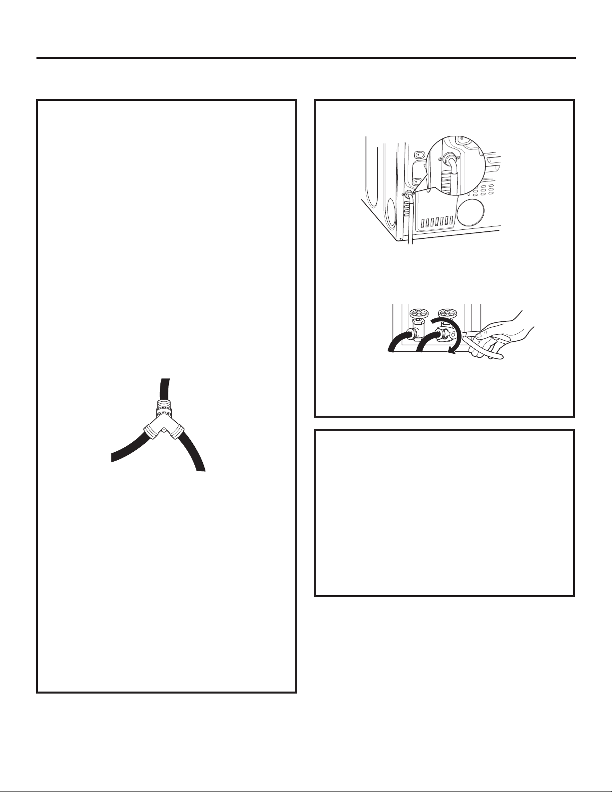
CONNECTING INLET HOSES
CONNECTING INLET HOSES
To produce steam, the dryer must connect to
the cold water supply. Since the washer must
also connect to the cold water, a “Y” connector
is inserted to allow both inlet hoses to make that
connection at the same time.
NOTE: Use the new inlet hoses provided; never use
old hoses.
1. Turn the cold water faucet off. Remove the
washer inlet hose from the washer fill valve
connector (cold).
2. Ensure the rubber flat washer is in place and
screw the female coupling of the short hose onto
the washer fill valve connector. Tighten by hand
until firmly seated.
3. Attach the female end of the ‘’Y’’ connector to
the male coupling of the short hose. Ensure the
rubber flat washer is in place. Tighten by hand
until firmly seated.
4. Insert the filter screen in the coupling of the
washer’s inlet hose. If a rubber flat washer is
already in place remove it before installing the
filter screen. Attach this coupling to one male end
of the ‘’Y’’ connector. Tighten by hand until firmly
seated.
5. Ensure the rubber flat washer is in place and
attach the dryer’s long inlet hose to the other
male end of the ‘’Y’’ connector. Tighten by hand
until firmly seated.
6. Ensure the rubber flat washer is in place and
attach the other end of the dryer’s long inlet
hose to the fill valve connector at the bottom of
the dryer back panel. Tighten by hand until firmly
seated.
CONNECTING INLET HOSES (cont.)
7. Using pliers, tighten all the couplings with an
additional two–thirds turn.
NOTE: Do not overtighten. Damage to the couplings
may result.
8. Turn the water faucet on.
9. Check for leaks around the ‘’Y’’ connector, faucet
and hose couplings.
WATER SUPPLY REQUIREMENTS
Hot and cold water faucets MUST be installed
within 42 in. (107 cm) of your washer’s water
inlet. The faucets MUST be 3/4 in. (1.9 cm) garden
hose-type so inlet hoses can be connected. Water
pressure MUST be between 10 and 120 pounds per
square inch. Your water department can advise you
of your water pressure.
NOTE: A water softener is recommended to reduce
buildup of scale inside the steam generator if the
home water supply is very hard.
18
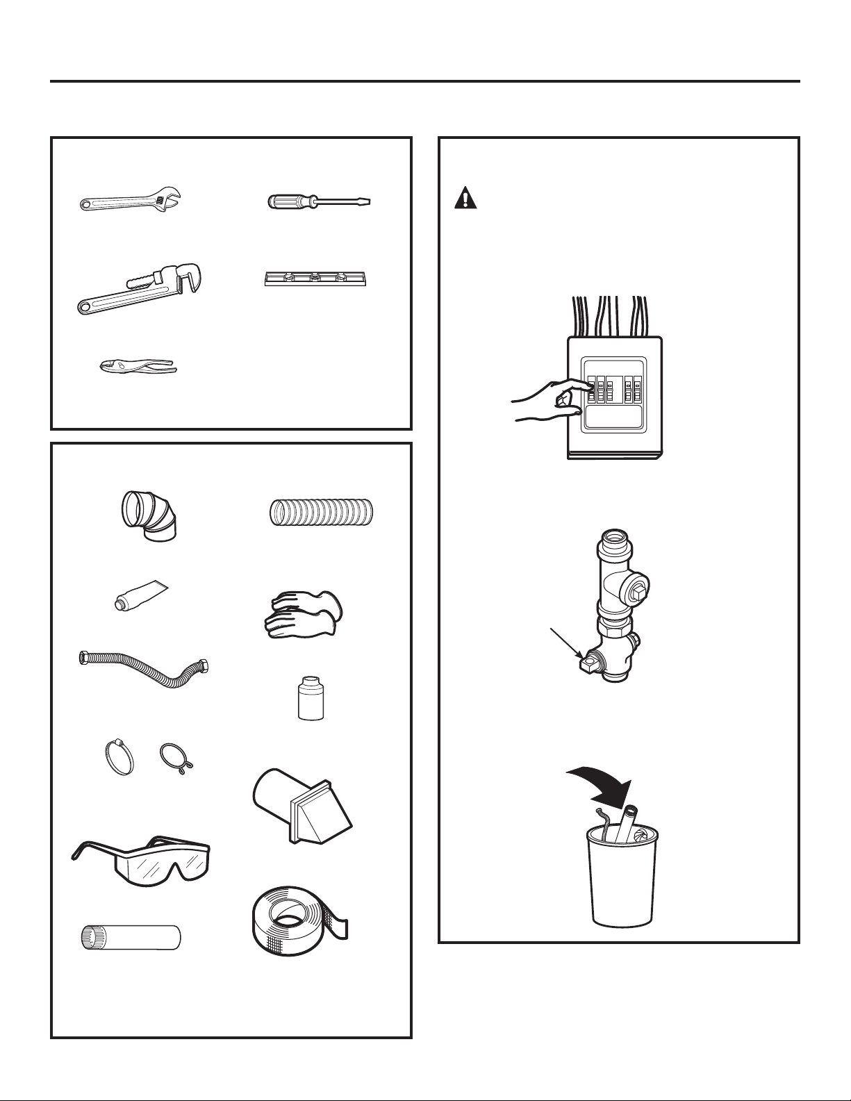
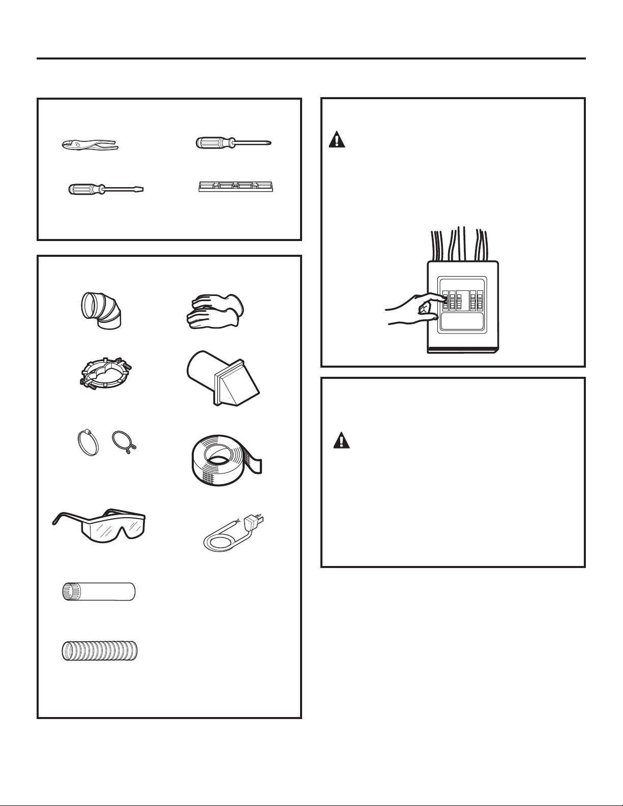
10” Adjustable
wrenches (2)
8” Pipe wrench
Slip-joint pliers
Flat-blade
screwdriver
Level
Installation Instructions
TOOLS YOU WILL NEED
CONNECTING A GAS DRYER (skip for electric dryers)
FOR YOUR SAFETY:
WARNING
Before beginning the installation, turn off
the circuit breaker(s) or remove the dryer’s circuit
fuse(s) at the electrical box. Be sure the dryer cord
is unplugged from the wall.
Turn the dryer’s gas shut-off valve in the supply
line to the OFF position.
Disconnect and discard old flexible gas connector
and ducting material.
Shut-off
Valve
MATERIALS YOU WILL NEED
4” dia. metal elbow
Pipe compound
Flexible gas line
connector
Duct clamps (2) or
Spring clamps (2)
Safety glasses
4” dia. metal duct
(recommended)
4” dia., UL-listed
flexible metal duct (if
needed)
Gloves
Soap solution for
leak detection
Exhaust hood
Duct tape
19
Installation Instructions
GAS REQUIREMENTS
WARNING
• Installation must conform to local codes and
ordinances, or in their absence, with the National
Fuel Gas Code, ANSI Z223.1/NFPA 54, or the Natural
Gas and Propane Installation Code, CSA B149.1.
•
This gas dryer is equipped with a Valve and
Burner Assembly for use only with natural gas.
Using conversion kit 14-A048, your local service
organization can convert this dryer for use with
propane (LP) gas. ALL CONVERSIONS MUST BE MADE
BY PROPERLY TRAINED AND QUALIFIED PERSONNEL
AND IN ACCORDANCE WITH LOCAL CODES AND
ORDINANCE REQUIREMENTS.
•
The dryer must be disconnected from the gas supply
piping system during any pressure testing of that
system at a test pressure in excess of 0.5 PSI (3.4
KPa).
•
The dryer must be isolated from the gas supply
piping system by closing the equipment shut-off
valve during any pressure testing of the gas supply
piping of test pressure equal to or less than 0.5 PSI
(3.4KPa).
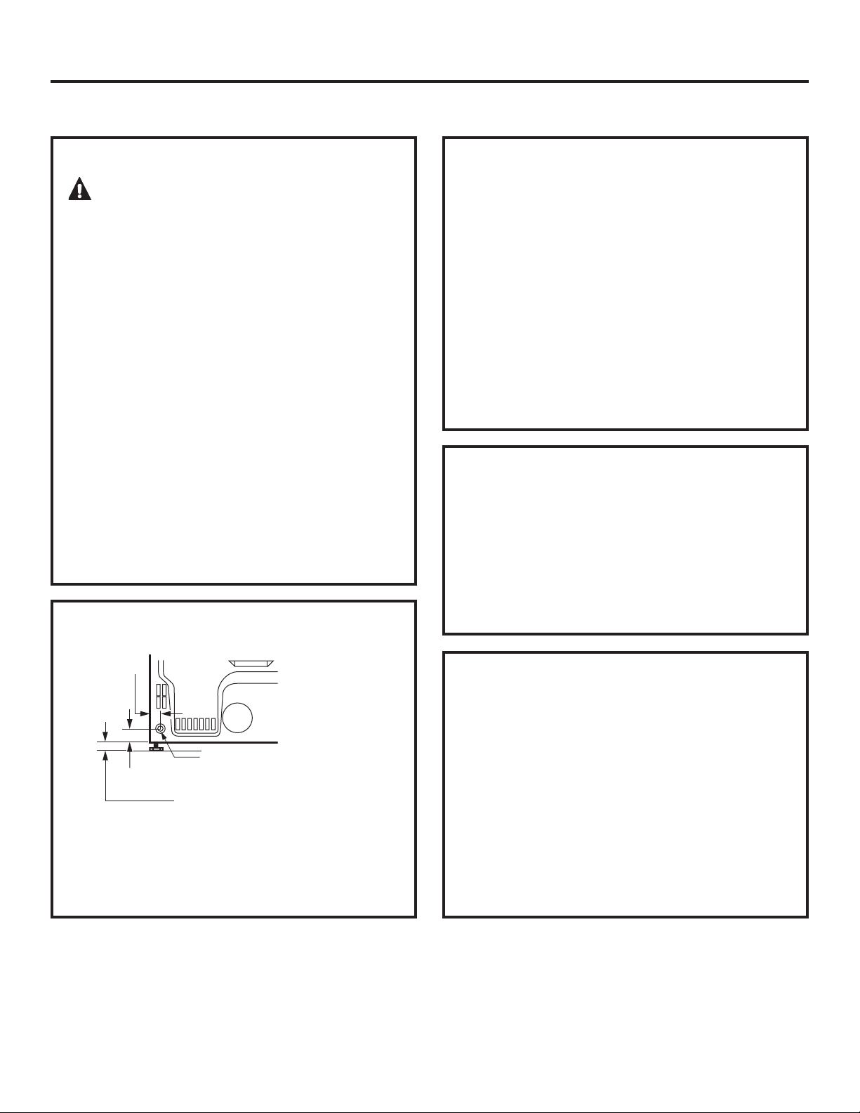
DRYER GAS SUPPLY CONNECTION
3/8” NPT MALE THREAD GAS SUPPLY
NOTE: Add to vertical dimension
the distance between cabinet
bottom to floor.
GAS SUPPLY
• A 1/8” National Pipe Taper thread plugged
tapping, accessible for test gauge connection,
must be installed immediately upstream of the
gas supply connection to the dryer. Contact
your local gas utility should you have questions
on the installation of the plugged tapping.
•
Supply line is to be 1/2” rigid pipe and equipped
with an accessible shutoff within 6 feet of, and
in the same room with, the dryer.
•
Use pipe thread compound appropriate for
natural or LP gas or use Teflon
®
tape.
•
Connect flexible metal connector to dryer and
gas supply.
IN THE COMMONWEALTH OF
MASSACHUSETTS
• This product must be installed by a licensed
plumber or gas fitter.
•
When using ball-type gas shut-off valves, they
shall be the T-handle type.
•
A flexible gas connector, when used, must not
exceed 3 feet.
2
5
ø8” (6.7 cm)
2” (5.1 cm)
ADJUSTING FOR ELEVATION
• Gas clothes dryers input ratings are based on
sea level operation and need not be adjusted
for operation at or below 2000 ft. elevation. For
operation at elevations above 2000 ft., input
ratings should be reduced at a rate of 4 percent
for each 1000 ft. above sea level.
•
Installation must conform to local codes and
ordinances or, in their absence, with the National
Fuel Gas Code, ANSI Z223.1/NFPA 54, or the
Natural Gas and Propane Installation Code, CSA
B149.1
You must use with this dryer a flexible metal
connector (listed connector ANSI Z21.24 / CSA 6.10).
The length of the connect shall not exceed 3 ft.
Install a 1/8” NPT plugged tapping to the dryer
gas line shut-off valve for checking gas inlet
pressure.
Install a flare union adapter to the plugged
tapping.
NOTE: Apply pipe compound or Teflon
®
tape
to the threads of the adapter and plugged
tapping.
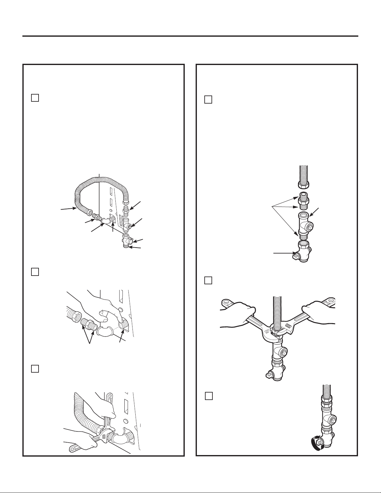
Installation Instructions
Attach the flexible metal gas line connector to
the adapter.
B
Tighten the flexible gas line connection, using
two adjustable wrenches.
C
D
Tighten all connections, using two adjustable
wrenches. Do not overtighten.
E
CONNECTING THE DRYER TO THE GAS
SUPPLY (cont.)
Apply pipe compound
or Teflon
®
tape to all
male threads.
Open the gas shut-off valve.
F
Shut-Off
Valve
Plugged
Tapping
CONNECTING THE DRYER TO THE GAS
SUPPLY
Install a female 3/8” NPT elbow at the end of the
dryer gas inlet.
Install a 3/8” flare union adapter to the female
elbow.
IMPORTANT: Use a pipe wrench to securely
hold on to the end of the dryer gas inlet to
prevent twisting the inlet.
NOTE: Apply pipe compound or Teflon
®
tape to
the threads of the adapter and dryer gas inlet.
A
Apply pipe compound to the
adapter and dryer gas inlet.
Elbow
Adapter
Items not supplied
Adapter
1/8” NPT
Pipe Plug for
Checking Gas
Inlet Pressure
Shut-Off Valve
Pipe size at
least 1/2”
3/8” NPT
New Metal
Flexible Gas
Line Connector
CONNECTING A GAS DRYER (cont.)
20
21
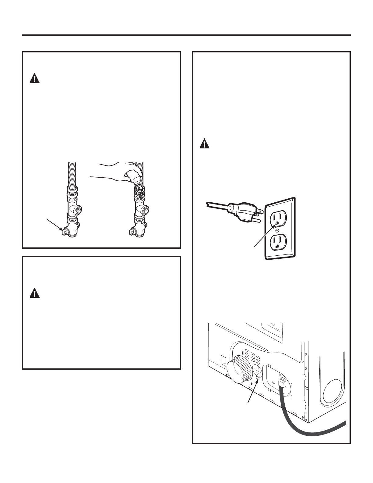
Installation Instructions
TEST FOR LEAKS
WARNING – Never use an open
flame to test for gas leaks.
Check all connections for leaks with soapy solution
or equivalent.
Apply a soap solution. The leak test solution must
not contain ammonia, which could cause damage
to the brass fittings.
If leaks are found, close the valve, retighten the joint
and repeat the soap test.
Open Gas
Valve
ELECTRICAL CONNECTION
INFORMATION FOR GAS DRYERS
WARNING – To reduce the risk of
fire, electrical shock and personal injury:
•
Do not use an extension cord or an adapter plug
with this appliance.
•
The dryer must be electrically grounded in
accordance with local codes and ordinances, or
in the absence of local codes, in accordance with
the NATIONAL ELECTRICAL CODE, ANSI/NFPA NO.
70 or Canadian Electrical Code, CSA C22.1
ELECTRICAL REQUIREMENTS FOR GAS
DRYERS
This appliance must be supplied with 120V, 60Hz,
and connected to a properly grounded branch
circuit, protected by a 15- or 20-amp circuit breaker
or time-delay fuse.
If electrical supply provided does not meet the
above specifications, it is recommended that a
licensed electrician install an approved outlet.
WARNING – This dryer is equipped
with a three-prong (grounding) plug for your
protection against shock hazard and should be
plugged directly into a properly grounded
three-prong receptacle. Do not cut or remove the
grounding terminal from this plug.
Ensure proper
ground exists
before use.
If local codes permit, an external ground wire (not
provided), which meets local codes, may be added
by attaching to the green ground screw on the rear
of the dryer, and to an alternate established ground.
Ensure proper ground exists before use.
Ground
Screw
Installation Instructions
CONNECTING AN ELECTRIC DRYER (skip for gas dryers)
ELECTRICAL CONNECTION
INFORMATION FOR ELECTRIC DRYERS
WARNING – To reduce the risk of
fire, electrical shock and personal injury:
•
Do not use an extension cord or an adapter plug
with this appliance.
•
The dryer must be electrically grounded in
accordance with local codes, or in the absence
of local codes, with the National Electrical Code,
ANSI/NFPA NO. 70 or Canadian Electrical Code,
CSA C22.1.
FOR YOUR SAFETY:
WARNING
Before making the electrical connection, turn off
the circuit breaker(s) or remove the dryer’s circuit
fuse(s) at the electrical box. Be sure the dryer cord
is unplugged from the wall. NEVER LEAVE THE
ACCESS COVER OFF THE TERMINAL BLOCK.
Slip-joint pliers
Flat-blade crewdriver
Phillips screwdriver
Level
TOOLS YOU WILL NEED
MATERIALS YOU WILL NEED
4” dia. metal elbow
3/4” strain relief
(UL recognized)
4”duct clamps (2) or
4”spring clamps (2)
Safety glasses
4” dia. metal duct
(recommended)
4” dia., UL-listed
flexible metal duct (if
needed)
Gloves
Exhaust hood
Duct tape
Dryer power cord kit
(not provided with
dryer)
UL rated 120/240V,
30A with 3 or 4 prongs.
Identify the plug type
as per the house
receptacle before
purchasing line cord.
22
23
Installation Instructions
ELECTRICAL REQUIREMENTS FOR
ELECTRIC DRYERS
This dryer must be connected to an individual
branch circuit, protected by the required time-delay
fuses or circuit breakers. A three- or four-wire,
single-phase, 120/240V or 120/208V, 60Hz, 30-amp
circuit is required.
If the electric supply does not meet the above
specifications, then call a licensed electrician.
This dryer must be connected to a grounded
metal, permanent wiring system, or an equipment-
grounding conductor must be run with the circuit
conductors and connected to the equipment
grounding terminal on the appliance.
NOTE: Since January 1, 1996, the National Electrical
Code requires that new constructions utilize a
4-wire connection to an electric dryer. A 4-wire cord
must also be used where local codes do not permit
grounding through the neutral.
3-wire connection is NOT for use on new
construction.
WARNING – NEVER LEAVE THE
COVER OFF OF THE TERMINAL BLOCK.
1. Turn off the circuit breaker(s) (30 amp) or remove
the dryer’s circuit fuse at the electrical box.
2.
Be sure the dryer cord is unplugged from the wall
receptacle.
3.
Remove the power cord cover located at the
lower back.
4.
Remove and discard ground strap. Keep the
green ground screw for Step 7.
5.
Install 3/4 in. UL-recognized strain relief to power
cord entry hole. Bring power cord through strain
relief.
6.
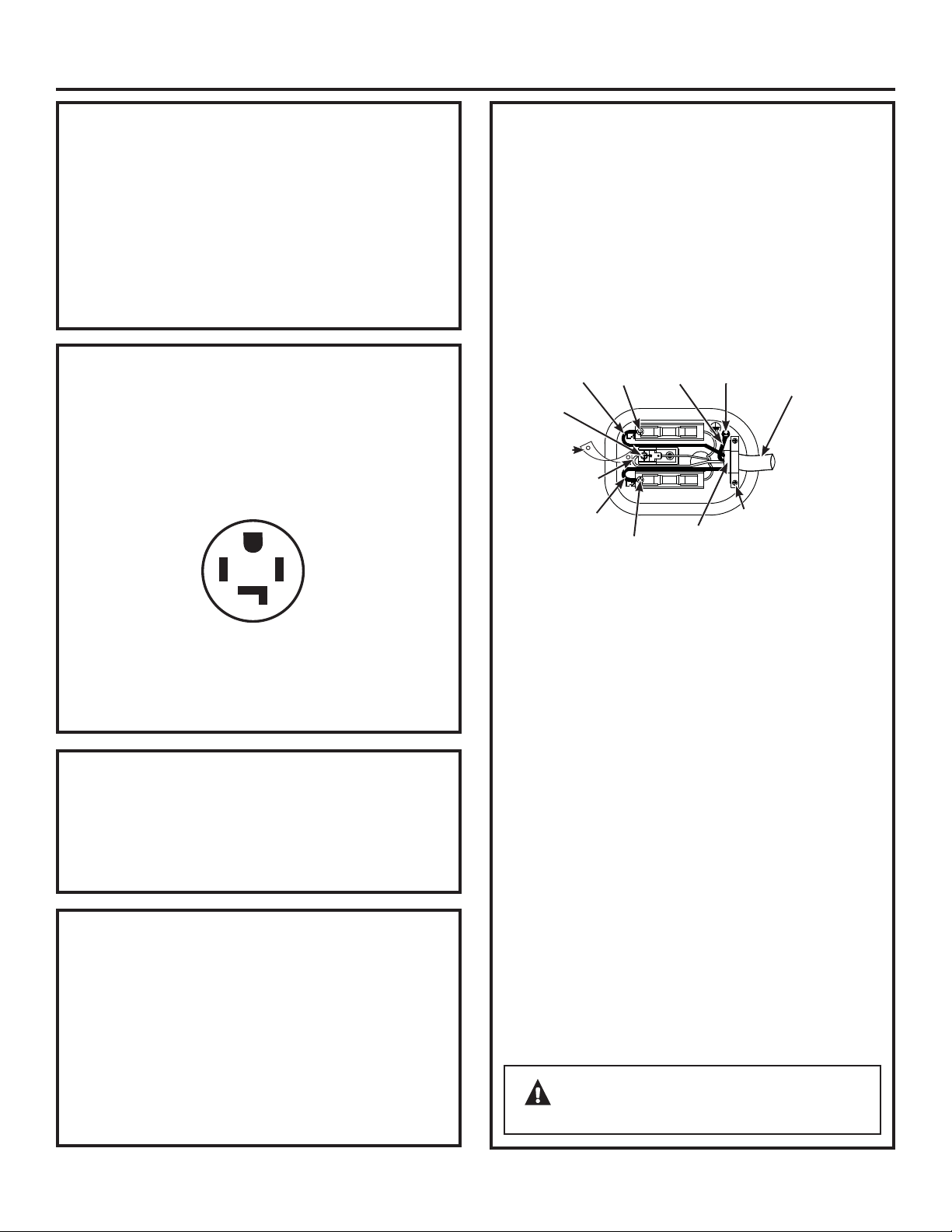
Connect power cord as follows:
A. Connect the 2 hot lines to the outer screws of
the terminal block (marked L1 and L2).
B. Connect the neutral (white) line to the center of
the terminal block (marked N).
7.
Attach ground wire of power cord with the green
ground screw (hole above strain relief bracket).
Tighten all terminal block screws (3) securely.
8.
Properly secure power cord to strain relief.
9.
Reinstall the cover.
4 #10 AWG
minimum
copper
conductors
or 120/240V
30A
power
supply cord
kit
marked for use
with dryers
and provided
with closed
loop or spade
terminals with
upturned ends
(not supplied)
Hot Wire
Hot Wire
Green
Wire
Relocatre
green ground
screw here
Neutral
(white)
3/4” UL
Recognized
Strain Relief
Strain
Relief
Bracket
Screw
Screw
Screw
Remove
ground strap
and discard.
Keep green
ground
screw.
CONNECTING DRYER USING 4-WIRE
CONNECTION (MUST BE USED FOR
MOBILE HOME INSTALLATION)
This appliance must be grounded. In the event
of malfunction or breakdown, grounding will
reduce the risk of electrical shock by providing
a path of least resistance for electrical current.
This appliance is equipped with a cord having an
equipment-grounding conductor and a grounding
plug. The plug must be plugged into an appropriate
outlet that is properly installed and grounded in
accordance with all local codes and ordinances.
ELECTRICAL REQUIREMENTS FOR
ELECTRIC DRYERS (CANADA)
This dryer must be connected to an individual
branch circuit, protected by the required time-delay
fuses or circuit breakers. The power supply must
be of 120/240 volts, 60Hz circuit with the wall
receptacle as shown below.
The power supply must be protected with 30 Amp
fuses or breakers. It must be well grounded and
conform to local codes.
TYPICAL 30 AMP
RECEPTACLE FOR DRYER
G
XY
W
GROUNDING INSTRUCTIONS
GROUNDING INSTRUCTIONS
(CANADA)
Installation Instructions
CONNECTING DRYER USING 3-WIRE
CONNECTION
CONNECTING DRYER USING 3-WIRE
CONNECTION (cont.)
WARNING – NEVER LEAVE THE
COVER OFF OF THE TERMINAL BLOCK.
CONNECTING AN ELECTRIC DRYER (cont.)
24
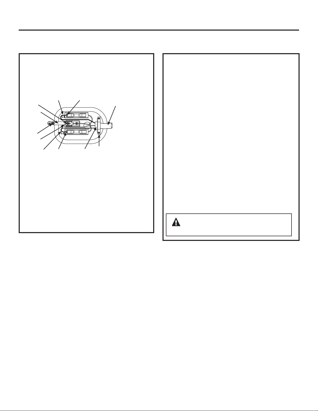
3-wire Connection
Not for use in Canada.
DO NOT use for Mobile Home Installations.
NOT for use on new construction.
NOT for use on recreational vehicles.
NOT for use in areas where local codes prohibit
grounding through the neutral conduction.
1.
Turn off the circuit breaker(s) (30 amp) or remove
the dryer’s circuit fuse at the electrical box.
2.
Be sure the dryer cord is unplugged from the wall
receptacle.
3.
Remove the power cord cover located at the lower
back.
4.
Install 3/4-in. UL-recognized strain relief to power
cord entry hole. Bring power cord through strain
relief.
5.
Connect power cord as follows:
A. Connect the 2 hot lines to the outer screws of
the terminal block (marked L1 and L2).
B. Connect the neutral (white) line to the center of
the terminal block (marked N).
6.
Be sure ground strap is connected to neutral
(center) terminal of block and to green ground
screw on cabinet rear. Tighten all terminal block
screws (3) securely.
7.
Properly secure power cord to strain relief.
8.
Reinstall the cover.
3 #10 AWG
minimum
copper
conductors or
120/240V 30A
power supply
cord kit marked
for use with
dryers and
provided with
closed loop or
spade terminals
with upturned
ends (not
supplied)
Hot Wire
Hot Wire
Green
ground
screw
Neutral
(white)
3/4” UL
Recognized
Strain Relief
Strain
Relief
Bracket
Screw
Screw
Screw
If required, by local code, install external ground (not
provided) to grounded metal, cold water pipe, or other
established ground determined by a qualified electrician.
Ground
Strap
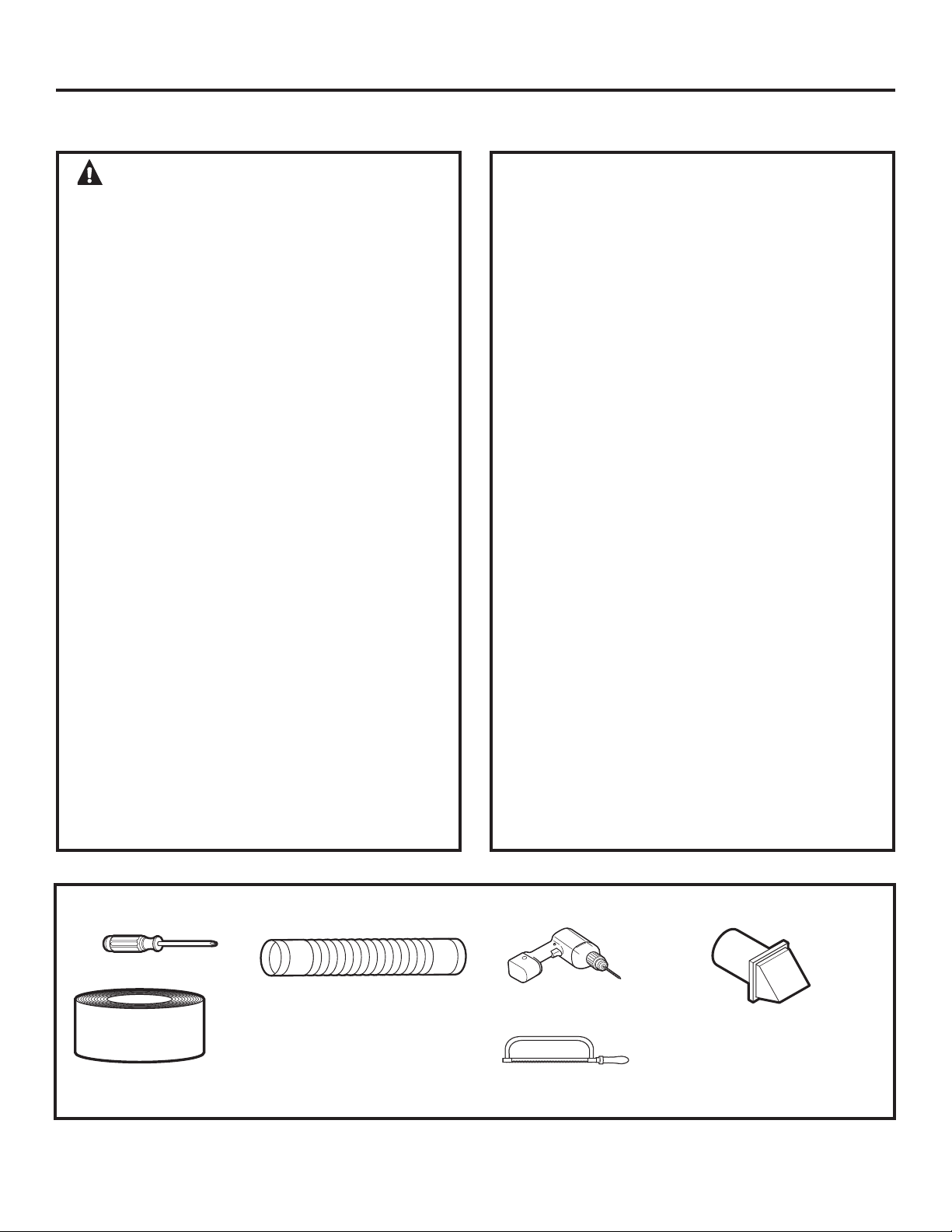
Phillips-head screwdriver
Duct tape or duct
clamp
Rigid or UL-listed
flexible metal 4” (10.2
cm) duct
Drill with 1/8” drill bit
(for bottom venting)
Hacksaw
Vent hood
25
Installation Instructions
EXHAUSTING THE DRYER
WARNING – To reduce the risk of fire
or personal injury:
•
This clothes dryer must be exhausted to the outdoors.
•
Use only 4” rigid metal ducting for the home exhaust
duct.
•
Use only 4” rigid metal or UL-listed flexible metal
(semi-rigid or foil-type) duct to connect the dryer
to the home exhaust duct. It must be installed
in accordance with the instructions found in
“Connecting the Dryer to House Vent” on page 26 of
this manual.
•
Do not terminate exhaust in a chimney, a wall,
a ceiling, gas vent, crawl space, attic, under an
enclosed floor, or in any other concealed space
of a building. The accumulated lint could cause a
potential fire hazard.
•
Never terminate the exhaust into a common duct
with a kitchen exhaust system. A combination of
grease and lint creates a potential fire hazard.
•
Do not use duct longer than specified in the exhaust
length table. Longer ducts can accumulate lint,
creating a potential fire hazard.
•
Never install a screen in or over the exhaust duct. This
will cause lint to accumulate, creating a potential fire
hazard.
•
Do not assemble ductwork with any fasteners
that extend into the duct. These fasteners can
accumulate lint, creating a potential fire hazard.
•
Do not obstruct incoming or exhausted air.
•
Provide an access for inspection and cleaning of
the exhaust system, especially at turns and joints.
Exhaust system shall be inspected and cleaned at
least once a year.
•
This dryer comes ready for rear exhausting. If space
is limited, use the instructions on pages 29–31 to
exhaust directly from the sides or bottom of the
cabinet.
EXHAUST SYSTEM CHECKLIST
HOOD OR WALL CAP
•
Terminate in a manner to prevent back drafts or entry
of birds or other wildlife.
•
Termination should present minimal resistance to
the exhaust airflow and should require little or no
maintenance to prevent clogging.
•
Never install a screen in or over the exhaust duct.
•
Wall caps must be installed at least 12” above ground
level or any other obstruction with the opening pointed
down.
SEPARATION OF TURNS
•
For best performance, separate all turns by at least 4
ft. of straight duct, including distance between last turn
and dampened wall cap.
SEALING OF JOINTS
•
All joints should be tight to avoid leaks. The male end of
each section of duct must point away from the dryer.
•
Do not assemble the ductwork with fasteners that
extend into the duct. They will serve as a collection
point for lint.
•
Duct joints should be made air- and moisture-tight
by wrapping the overlapped joints with duct tape or
aluminum tape.
•
Horizontal runs should slope down towards the
outdoors 1/4” per foot.
INSULATION
•
Ductwork that runs through an unheated area or is
near air conditioning should be insulated to reduce
condensation and lint buildup.
TOOLS AND MATERIALS YOU WILL NEED TO INSTALL EXHAUST DUCT
EXHAUSTING THE DRYER (cont.)
Installation Instructions
CONNECTING THE DRYER TO HOUSE
VENT
RIGID METAL TRANSITION DUCT
•
For best drying performance, a rigid metal transition
duct is recommended.
•
Rigid metal transition ducts reduce the risk of crushing
and kinking.
UL-LISTED FLEXIBLE METAL (SEMI-RIGID) TRANSITION
DUCT
•
If rigid metal duct cannot be used, then UL-listed
flexible metal (semi-rigid) ducting can be used (Kit
WX08X10077).
•
Never install flexible metal duct in walls, ceilings, floors
or other enclosed spaces.
•
Total length of flexible metal duct should not exceed 8
feet (2.4 m).
•
For many applications, installing elbows at both
the dryer and the wall is highly recommended (see
illustrations at right). Elbows allow the dryer to sit
close to the wall without kinking and/or crushing the
transition duct, maximizing drying performance.
•
Avoid resting the duct on sharp objects.
UL-LISTED FLEXIBLE METAL (FOIL-TYPE) TRANSITION
DUCT
•
In special installations, it may be necessary to connect
the dryer to the house vent using a flexible metal
(foil-type) duct. A UL-listed flexible metal (foil-type) duct
may be used ONLY in installations where rigid metal or
flexible metal (semi-rigid) ducting cannot be used AND
where a 4
”
diameter can be maintained throughout
the entire length of the transition duct.
•
In Canada and the United States, only the flexible
metal (foil-type) ducts that comply with the “Outline for
Clothes Dryer Transition Duct Subject 2158A” shall be
used.
•
Never install flexible metal duct in walls, ceilings, floors
or other enclosed spaces.
•
Total length of flexible metal duct should not exceed 8
feet (2.4 m).
•
Avoid resting the duct on sharp objects.
•
For best drying performance:
1. Slide one end of the duct over the clothes dryer
outlet pipe.
2. Secure the duct with a clamp.
3. With the dryer in its permanent position, extend
the duct to its full length. Allow 2
”
of duct to
overlap the exhaust pipe. Cut off and remove
excess duct. Keep the duct as straight as possible
for maximum airflow.
4. Secure the duct to the exhaust pipe with the
other clamp.
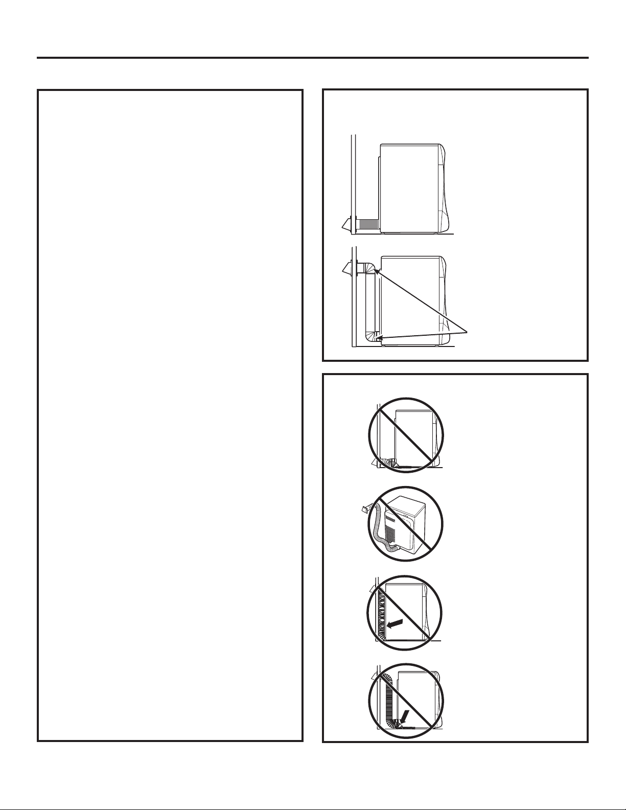
FOR TRANSITION VENTING (DRYER TO
WALL), DO:
• DO cut duct as
short as possible
and install
straight into wall.
•
DO use elbows
when turns are
necessary.
DO NOT:
Elbows
26
• DO NOT bend or
collapse ducting.
Use elbows
if turns are
necessary.
•
DO NOT use
excessive
exhaust length.
Cut duct as short
as possible.
• DO NOT crush
duct against the
wall.
•
DO NOT set
dryer on duct.
27
Installation Instructions
EXHAUST SYSTEM CHECKLIST
HOOD OR WALL CAP
•
Terminate in a manner to prevent back drafts or
entry of birds or other wildlife.
•
Termination should present minimal resistance
to the exhaust airflow and should require little or
no maintenance to prevent clogging.
•
Never install a screen in or over the exhaust
duct. This could cause lint buildup.
•
Wall caps must be installed at least 12” above
ground level or any other obstruction with the
opening pointed down.
SEPARATION OF TURNS
For best performance, separate all turns by at
least 4 ft. of straight duct, including the distance
between the last turn and the exhaust hood.
TURNS OTHER THAN 90º
• One turn of 45º or less may be ignored.
•
Two 45º turns should be treated as one 90º turn.
•
Each turn over 45º should be treated as one 90º
turn.
SEALING OF JOINTS
•
All joints should be tight to avoid leaks. The male
end of each section of duct must point away
from the dryer.
•
Do not assemble the ductwork with fasteners
that extend into the duct. They will serve as a
collection point for lint.
•
Duct joints can be made air- and moisture-tight
by wrapping the overlapped joints with duct
tape.
•
Horizontal runs should slope down toward the
outdoors 1/4” per foot.
INSULATION
Ductwork that runs through an unheated area or is
near air conditioning should be insulated to reduce
condensation and lint buildup.
WARNING – USE ONLY METAL 4”
DUCT. DO NOT USE DUCT LONGER THAN
SPECIFIED IN THE EXHAUST LENGTH TABLE.
Using exhaust longer than specified length will:
•
Increase the drying times and the energy cost.
•
Reduce the dryer life.
•
Accumulate lint, creating a potential fire
hazard.
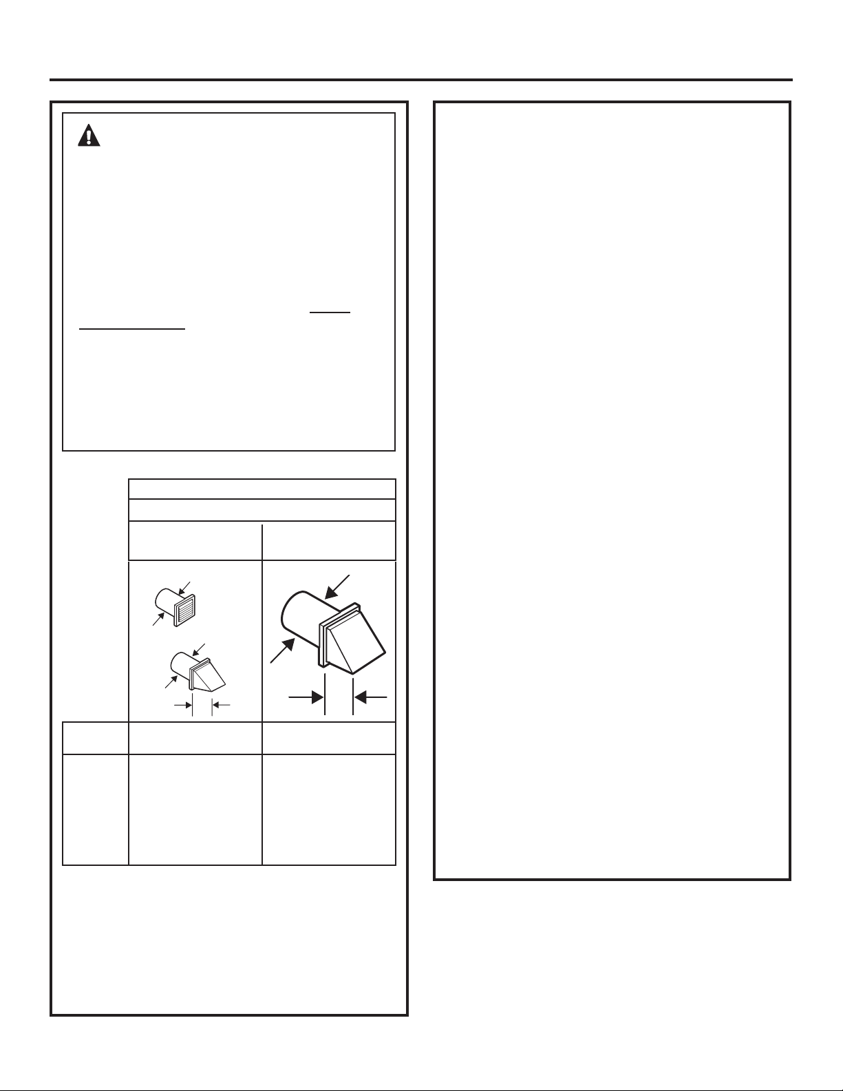
The correct exhaust installation is YOUR
RESPONSIBILITY.
Problems due to incorrect installation are not
covered by the warranty.
The MAXIMUM ALLOWABLE length of the
exhaust system depends upon the type of duct,
number of turns, the type of exhaust hood (wall
cap) and all conditions noted below.
EXHAUST LENGTH
RECOMMENDED MAXIMUM LENGTH
Exhaust Hood Types
Recommended Use only for short- run
installations
No. of 90º Rigid Rigid
Elbows Metal Metal
0 150 Feet 125 Feet
1 135 Feet 115 Feet
2 125 Feet 105 Feet
3 115 Feet 95 Feet
4 105 Feet 85 Feet
5 95 Feet 75 Feet
4
”
DIA
4
”
2
1
ø2”
4
”
DIA
4
”
DIA
• For every extra 90° elbow, reduce the allowable vent
system length by 10 ft.
• Two 45° elbows will be treated like one 90° elbow.
• For the side exhaust installations, add one 90° elbow to
the chart.
• The total vent system length includes all the straight
portions and elbows of the system (transition duct
included).
EXHAUSTING THE DRYER (cont.)
Installation Instructions
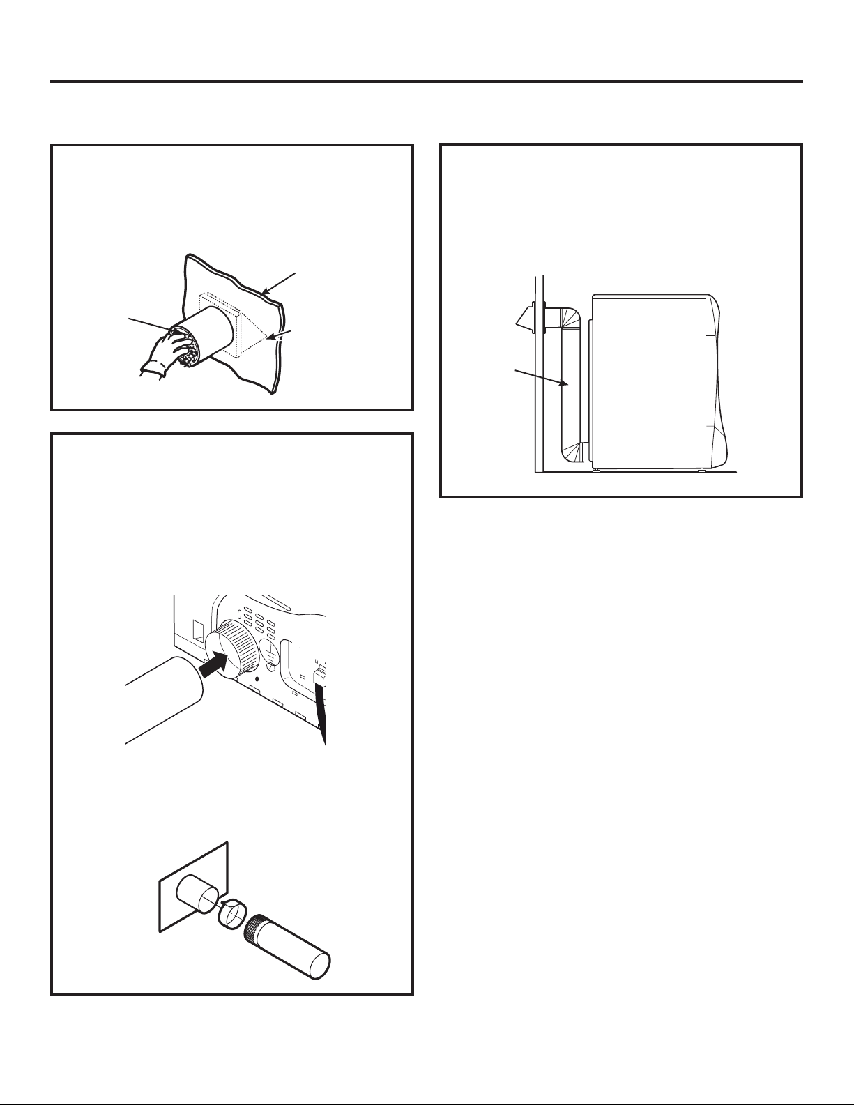
BEFORE YOU BEGIN
• Remove and discard existing plastic or metal foil
duct and replace with UL-listed duct.
•
Remove any lint from the wall exhaust opening.
Internal
Duct
Opening
Wall
Check that exhaust
hood damper opens
and closes freely.
STANDARD REAR EXHAUST
We recommend that you install your dryer before
installing your washer. This will permit direct
access for easier exhaust connection.
Slide the end of the exhaust duct on the back of the
dryer and secure with duct tape or a hose clamp.
NOTE: We strongly recommend using rigid metal
exhaust duct.
•
For straight-line installation, connect the dryer
exhaust to the wall, using duct tape.
RECOMMENDED CONFIGURATION TO
MINIMIZE EXHAUST BLOCKAGE
Using duct elbows will prevent duct kinking and
collapsing.
Duct
Transition
Ducting
Wall Side
Dryer
Side
28
29
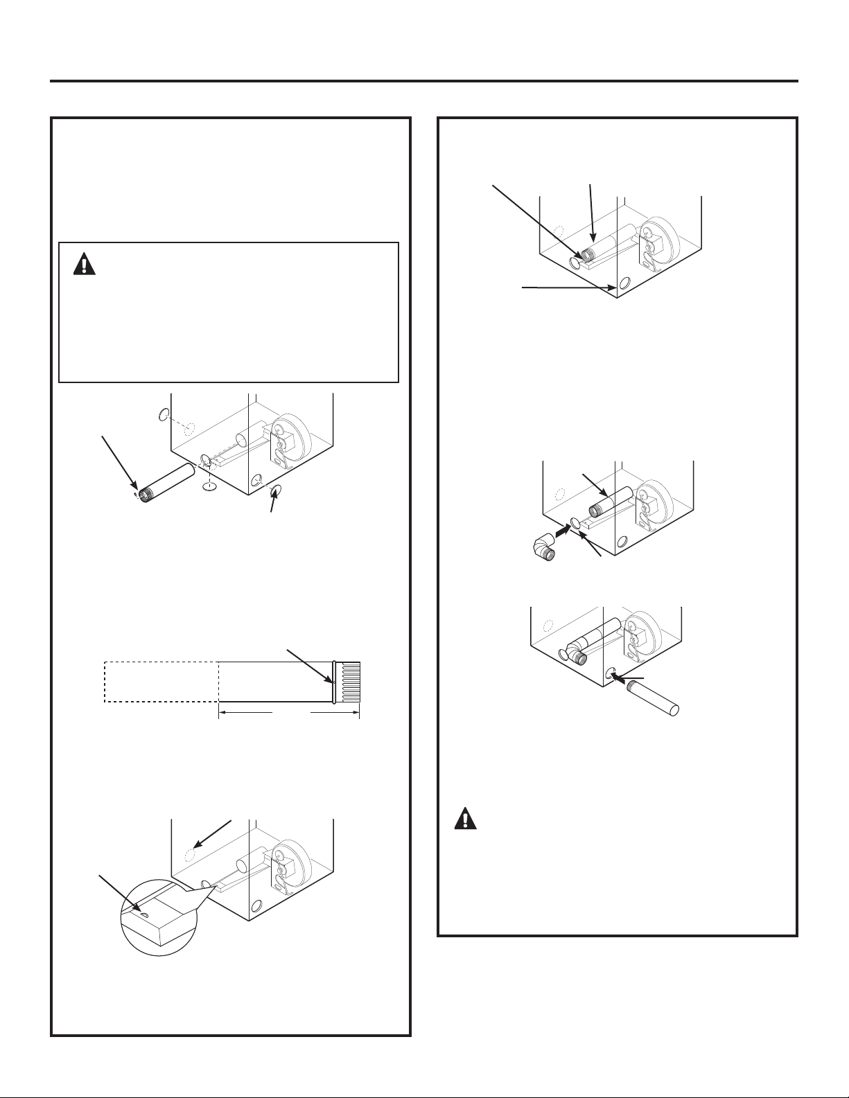
WARNING – BEFORE PERFORMING
THIS EXHAUST INSTALLATION, BE SURE TO
DISCONNECT THE DRYER FROM ITS ELECTRICAL
SUPPLY. PROTECT YOUR HANDS AND ARMS
FROM SHARP EDGES WHEN WORKING INSIDE
THE CABINET. BE SURE TO WEAR GLOVES.
Installation Instructions
SIDE VENTING:
Dryer Exhaust to right of cabinet for Electric
models only.
Dryer Exhaust to left of cabinet for Gas and
Electric models.
Detach and remove the bottom, right or left side
knockout as desired. Remove the screw inside the
dryer exhaust duct and save. Pull the duct out of
the dryer.
Remove
screw
and save
Remove desired
knockout (one only)
Fixing hole
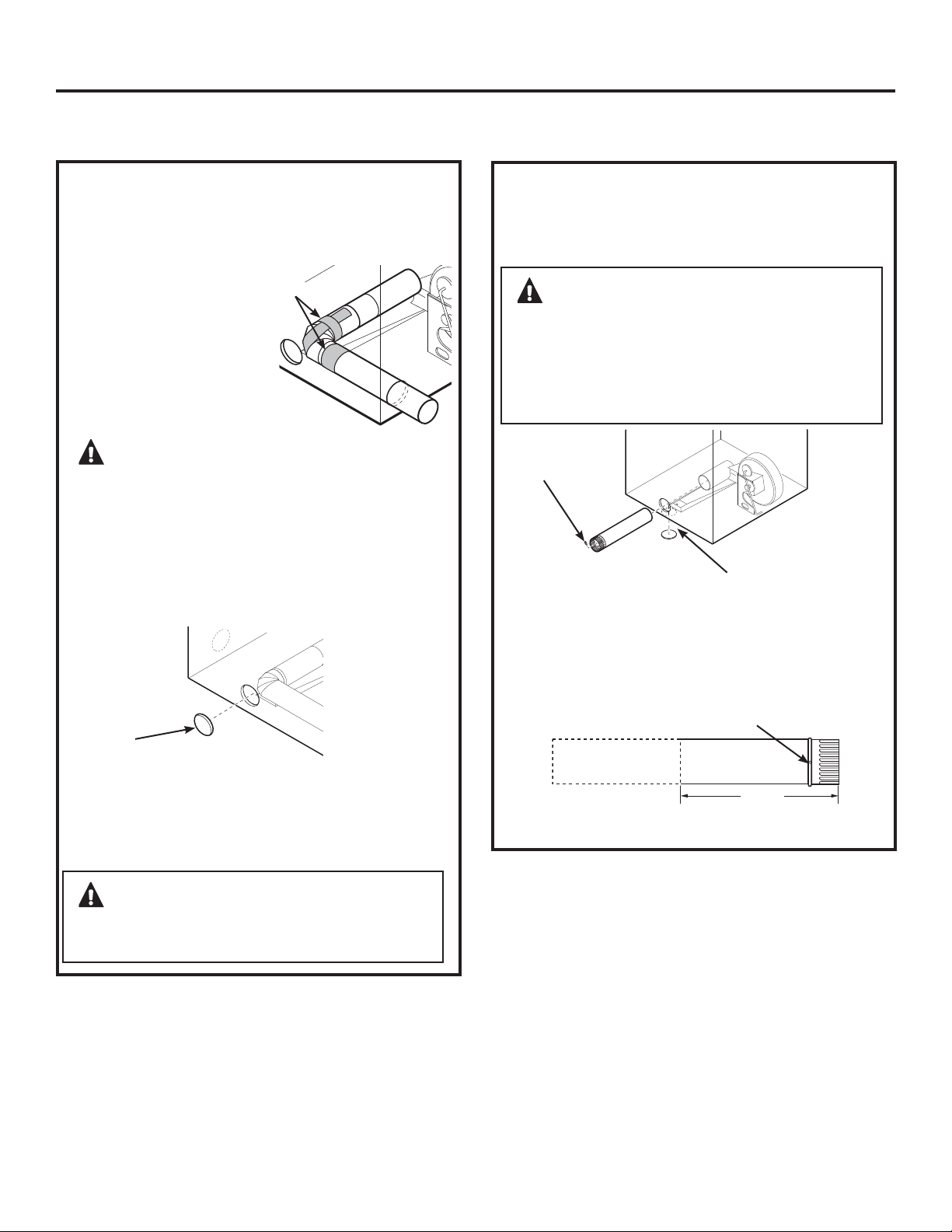
Cut the duct as shown and keep portion A.
TAB LOCATION
Bend tab
up 45°
Through the rear opening, locate the tab in the
middle of the appliance base. Lift the tab to about
45°,
using a flat-blade screwdriver.
ADDING A NEW DUCT
Reconnect the cut portion (A) of the duct to the
blower housing. Make sure that the shortened
duct is aligned with the tab in the base. Use the
screw saved previously to secure the duct in place
through the tab on the appliance base.
ADDING ELBOW AND DUCT FOR EXHAUST TO
LEFT OR RIGHT SIDE OF CABINET
• Insert the 4” elbow through the rear opening and
connect the elbow to the dryer internal duct.
•
Insert the 4” duct through the side opening and
connect it to the elbow.
CAUTION: Do not pull or damage the
electrical wires and do not remove the vinyl cover
from the electrical components inside the dryer
when inserting the duct. A slight interference may
occur between the exhaust and the wire
components.
Portion “A”
Left side
exhaust
Fixing hole
Internal duct
Not for gas
A
13
1
ø2”
Right
Left
Bottom
Rear opening
Side opening
EXHAUSTING THE DRYER (cont.)
WARNING – NEVER LEAVE THE
BACK OPENING WITHOUT THE PLATE.
(Kit
WE1M454)
Installation Instructions
SIDE VENTING (cont.)
Connect standard metal elbows and ducts to
complete the exhaust system. Cover back opening
with a plate (Kit WE1M454) available from your
local service provider. Place dryer in final location.
ADDING COVER PLATE TO REAR OF CABINET
(SIDE EXHAUST)
ADDING ELBOW AND DUCT FOR EXHAUST TO
LEFT OR RIGHT SIDE OF CABINET (cont.)
Plate
(Kit WE1M454)
• Apply duct tape as
shown on the joint
between the dryer
internal duct and the
elbow, and also the
joint between the
elbow and the side
duct.
CAUTION: Use 4” rigid metal ducting
only inside the dryer. Internal duct joints must be
secured with tape, otherwise they may separate
and cause a safety hazard.
Duct tape
WARNING – BEFORE PERFORMING
THIS EXHAUST INSTALLATION, BE SURE TO
DISCONNECT THE DRYER FROM ITS ELECTRICAL
SUPPLY. PROTECT YOUR HANDS AND ARMS
FROM SHARP EDGES WHEN WORKING INSIDE
THE CABINET. BE SURE TO WEAR GLOVES.
BOTTOM VENTING:
Dryer Exhaust to the bottom of cabinet for
Gas and Electric models.
Remove the screw inside the dryer exhaust duct
and save. Pull the duct out of the dryer. Detach and
remove the bottom knockout.
Remove
screw
and save
Remove desired
knockout (one only)
Fixing hole
Cut the duct as shown and keep portion A.
A
13
1
ø4”
Bottom
30
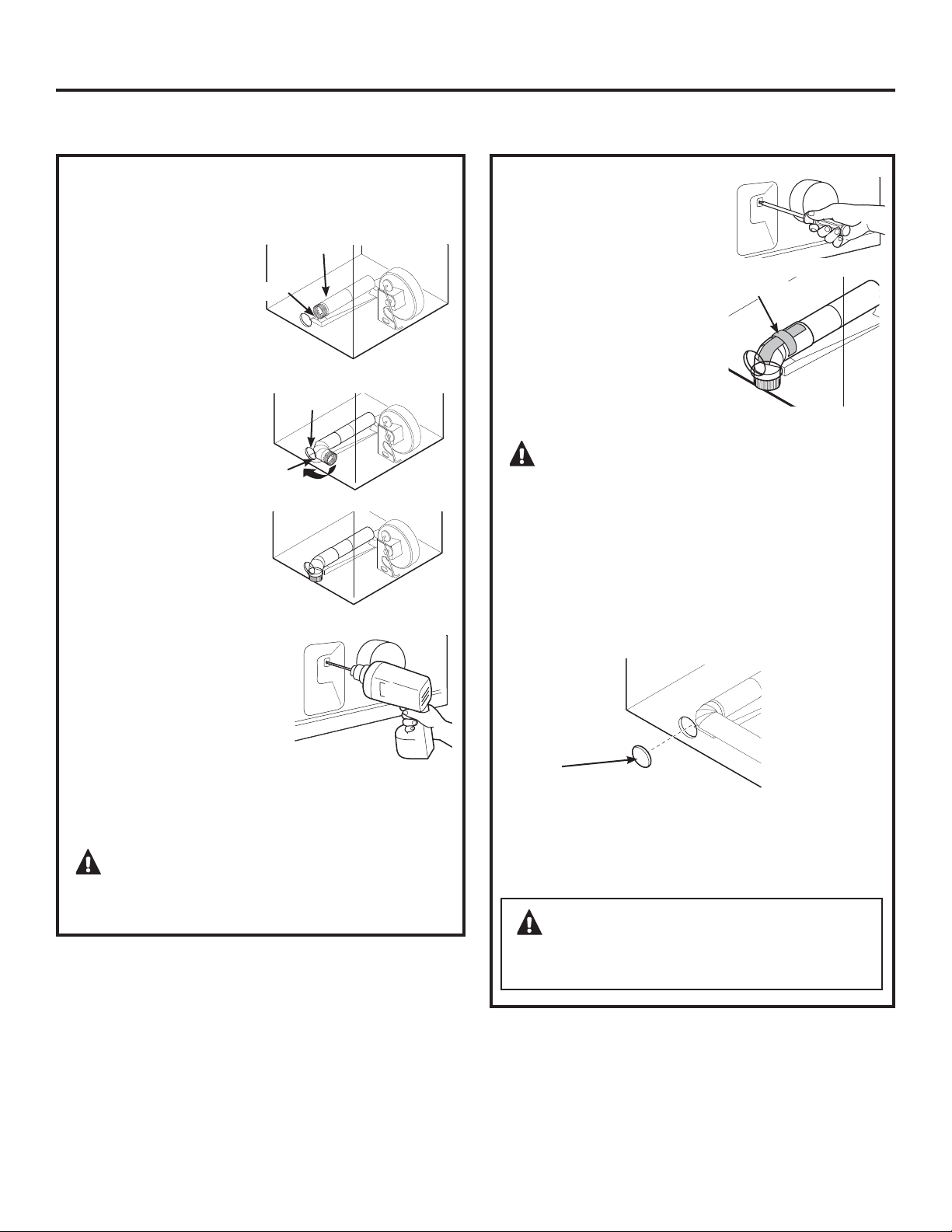
• Reconnect the cut
portion A of the
duct to the blower
housing.
•
Tape the elbow
in a 90-degree
position to prevent
rotation.
•
Insert the elbow
through the rear
hole and connect
it to portion A.
Rotate the elbow
through the
bottom opening.
•
While holding down
the pipe and elbow,
using your hand
through the rear
opening, drill a 1/8”
hole through the
bottom tab hole and
the pipe as shown
in the illustration.
NOTE: Make sure the hole is drilled all the way
through the elbow and pipe.
CAUTION: Be sure not to pull or
damage the electrical wires inside the dryer when
inserting the duct.
31
WARNING – NEVER LEAVE THE
BACK OPENING WITHOUT THE PLATE.
(Kit
WE1M454)
Dryer Exhaust to the bottom of cabinet for
Gas and Electric models.
BOTTOM VENTING (cont.)
Connect standard metal elbows and ducts to
complete the exhaust system. Cover back opening
with a plate (Kit WE1M454) available from your
local service provider. Place dryer in final location.
ADDING COVER PLATE TO REAR OF CABINET
(BOTTOM EXHAUST)
Plate
(Kit WE1M454)
Installation Instructions
• While still holding down
the pipe and elbow from
the rear opening, screw
the pipes in place with the
previously saved screw.
•
Apply duct tape as shown
on the joint between the
dryer internal duct and the
elbow.
NOTE: Make sure the tape
covers the screw hole in
portion A where it connects
to the elbow.
CAUTION: Internal duct joints must
be secured with tape; otherwise, they may
separate and cause a safety hazard.
Duct tape
Rear hole
Bottom
opening
Bottom view
Portion “A”
Fixing hole
ADDING A NEW DUCT
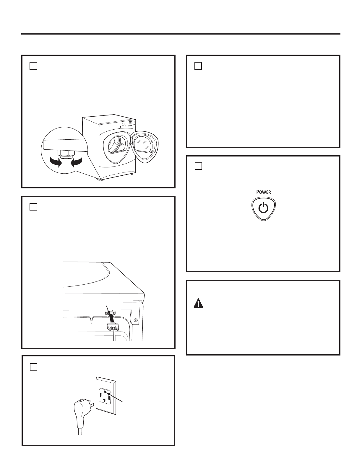
FINAL SETUP
Installation Instructions
LEVEL THE DRYER
Stand the dryer upright near the final location
and adjust the four leveling legs at the corners to
ensure that the dryer is level from side to side and
front to rear.
Lower
Raise
ATTACH SERIAL CABLE
Attach the serial cable for washer and dryer
connection to the serial port on the back of the
dryer.
Attach the other end of the cable to the washer
before pushing the washer into its final position.
PLUG DRYER IN
Ensure proper
ground exists
before use.
Rear of
Dryer
1
2
3
Serial Port
GROUNDING INSTRUCTIONS
This appliance must be grounded. In the event of
malfunction or breakdown, grounding will reduce
the risk of electric shock by providing a path of
least resistance for electric current. This appliance
is equipped with a cord having an equipment-
grounding conductor and a grounding plug.
The plug must be plugged into an appropriate
outlet that is properly installed and grounded in
accordance with all local codes and ordinances.
4
DRYER STARTUP
Press the POWER button.
NOTE: If the dryer has been exposed to temperatures
below freezing for an extended period of time, allow
it to warm up before pressing POWER. Otherwise,
the display will not come on.
The dryer is now ready for use.
5
SERVICING
WARNING – Label all wires prior to
disconnection when servicing controls. Wiring
errors can cause improper and dangerous
operation after servicing/installation.
For replacement parts and other information, refer
to the back cover for servicing phone numbers.
32
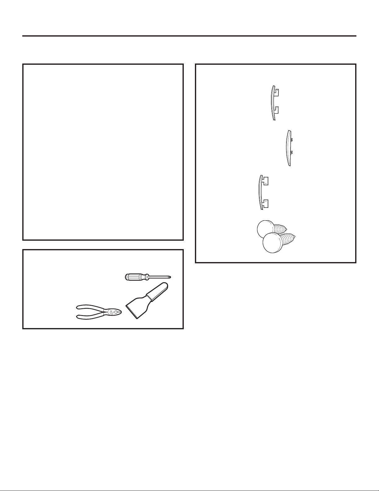
33
Phillips-head screwdriver or
quadrex head screwdriver
Putty knife or thin-blade
screwdriver
Pliers
Installation Instructions
REVERSING THE DOOR SWING (if desired)
IMPORTANT NOTES
• Read the instructions all the way through before
starting.
• Handle parts carefully to avoid scratching paint.
• Provide a non-scratching work surface for
the doors.
• Set screws down by their related parts to avoid
using them in the wrong places.
• All screws must be hand-tightened.
• Normal completion time to reverse the door
swing is 30–60 minutes.
IMPORTANT: Once you begin, do not move the
cabinet until door-swing reversal is completed.
These instructions are for changing the hinges
IURP WKH ULJKW VLGH WR WKH OHIW VLGH³LI \RX HYHU
want to switch them back to the right side, follow
these same instructions and reverse all references
to the left and right.
TOOLS YOU WILL NEED
STANDARD REVERSIBILITY KIT
Chrome door cap
Chrome door hinge cap
Inner door cap
2 Plug buttons
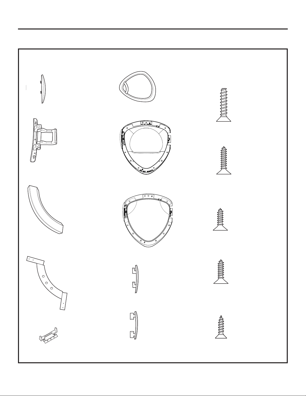
REVERSING THE DOOR SWING (if desired)
DOOR PARTS
Hinge cap
Hinge assembly
Outer handle
Inner handle
2 Handle caps
Chrome door cover
Inner cover (Mask)
Outer window
Chrome door cap
Inner door cap
A Large tapping screws
7 – #10 x 1.125”
B Large tapping screws
2 – #10 x 0.750”
C Small tapping screw
1 – #8 x 0.375”
D Small tapping screws
11 – #8 x 0.625”
E Machine screws
4 – #8 x 0.50”
Installation Instructions
34
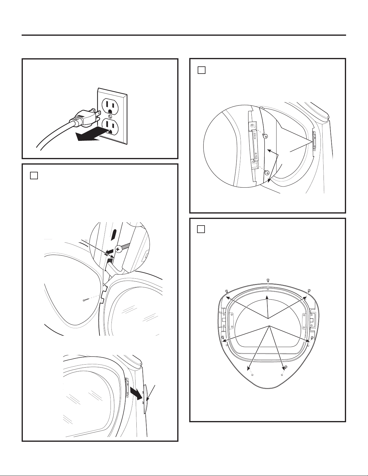
35
REMOVE THE DOOR ASSEMBLY
Remove the side hinge cap by opening the dryer
door and removing the screw from behind the
hinge (#8 x .375” tapping screw). Then using your
hand, pop the hinge cap off the dryer.
Hinge
cap
1
DISASSEMBLE THE DOOR ASSEMBLY
2
Turn the door assembly over and separate the
chrome cover from the inner door. Put the inner
door aside on a soft, protected flat surface.
Lay the door down on a soft, protected, flat surface
so that the inner part faces upward (door resting on
the handle side).
Remove the 7 screws (#10 x 1.125” tapping screws)
located around the perimeter of the door.
7 x A Screws
Installation Instructions
BEFORE YOU START
Unplug the dryer from its electrical outlet.
REMOVE THE DOOR ASSEMBLY (cont.)
1
Close and hold the door, remove the 2 hinge screws
(#10 x 0.75” tapping screws). Pull the door away
from the dryer front panel.
2 x B
Screws
1 x C Screw
REVERSING THE DOOR SWING (if desired)
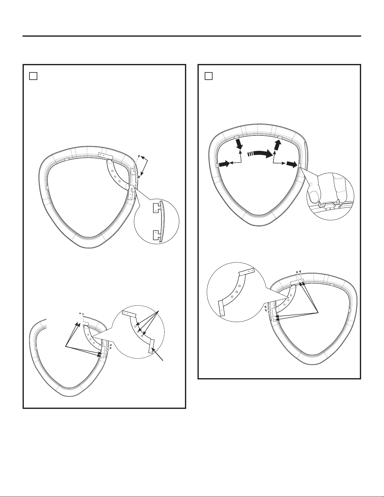
REVERSING THE DOOR SWING (if desired)
Installation Instructions
REVERSE DOOR HANDLE AND CAPS
A Lay the chrome cover down on a soft, protected,
flat surface so that the inner part faces upward
(resting on the handle side). Disassemble the
door cap from the chrome cover on the handle
side by removing 2 screws (#8 x 0.625” tapping
screws).
Door cap
3
D Assemble the inner handle onto the opposite
side of the chrome cover, using 4 screws (#8 x
0.625” tapping screws).
REVERSE DOOR HANDLE AND CAPS
(CONT.)
C Pop the 2 handle caps out toward you and
reassemble on the opposite side of the chrome
cover, where you removed the outer handle.
3
B Disassemble the outer handle from the inner
handle by removing 3 screws (#8 x 0.625” tapping
screws). Disassemble the inner handle from the
chrome cover by removing 4 screws (#8 x 0.625”
tapping screws).
2 x D
Screws
Remove
4 x D screws
(Inner handle)
Handle caps
Replace
4 x D
screws
(Inner
handle)
Inner
handle
3 x D
Screws
(Outer
handle)
Inner
handle
36
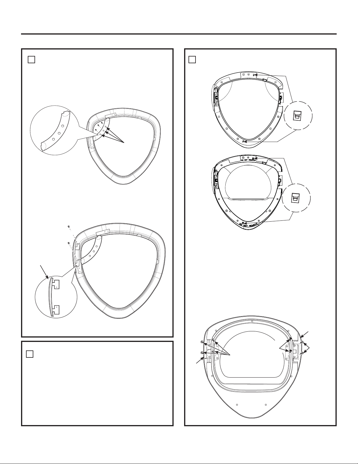
REVERSE DOOR HANDLE AND CAPS
(CONT.)
Put the chrome cover aside on a soft, protected
flat surface.
Door cap
3
F Assemble the new right-side door cap (from
reversibility kit), using 2 screws (#8 x 0.625” tapping
screws).
REVERSE HINGE AND CAPS (CONT.)
Installation Instructions
2 x D Screws
3 x D
Screws
(inner
handle)
E Reassemble the outer handle to the inner handle,
using 3 screws (#8 x 0.625” tapping screws).
Outer
handle
REVERSE HINGE AND CAPS
• Lay the inner door down on a soft , protected
flat surface so that the inner part faces down.
Disassemble the outer window by opening 2 snaps,
lay the outer window on a soft, protected flat
surface.
• Disassemble the inner cover (mask) by opening
2 snaps, lay the inner cover (mask) on a soft,
protected flat surface.
4
Outer window
Inner cover
(Mask)
• Turn the inner door on a soft , protected flat
surface so that the inner part faces up.
• Remove the screws, nuts and washers on the
opposite side of the hinge, using a quadrex
screwdriver.
• Disassemble the inner door cap from the inner
door by removing 2 screws (#8 x 0.75” tapping
screws).
• Disassemble the hinge from the inner door by
removing 4 screws (#8-32 x 0.50” machine screws).
Hinge
Remove
4 x E screws
2 x D
Screws
Inner
door cap
2 screws,
2 nuts and
2 washers
Snap
Snap
37
4
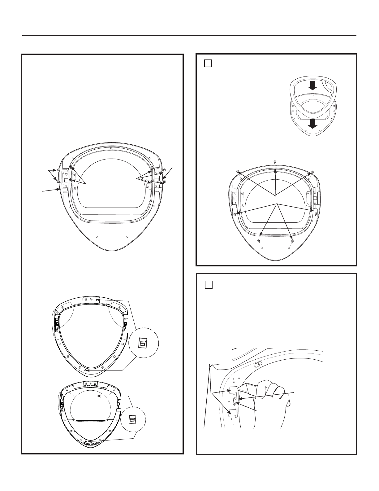
REVERSING THE DOOR SWING (if desired)
REVERSE HINGE AND CAPS (CONT.)
• Assemble the hinge to the opposite side of the
inner door, using 4 screws (#8-32 x 0.50” machine
screws).
• Assemble the new inner door cap (from reversibility
kit) on the opposite side of the hinge, using 2
screws (#8 x 0.75” tapping screws).
• Install the the screws, nuts and washers on the
opposite side of the hinge in the 2 remaining holes.
• Flip the inner door so that the inner part faces down.
Assemble the inner cover (mask), be sure the snaps
have clamped the inner cover. Assemble the outer
window, be sure the 2 snaps have clamped the outer
window.
Replace
4 x E
screws
Replace
2 x D
screws
Inner
door
cap
Replace
2 screws,
2 nuts and
2 washers
Installation Instructions
REASSEMBLE DOOR ASSEMBLY
Turn the inner door over
and place on a soft,
protected flat surface
so that the inner part is
facing down. Assemble
the chrome cover to the
inner door by placing
them together. Flip the
door assembly over and
assemble, using 7 screws
(#10 x 1.125” tapping
screws).
5
7 x A Screws
REVERSE FRONT PANEL PLUG
BUTTONS AND STRIKE PLATE
Remove the 2 plug buttons on the dryer front
panel, using a putty knife or other flat tool as
shown, and reinstall on the opposite side. Switch
the strike bracket and its cover by removing 2
screws (#8 x 0.625” tapping screws) for each and
reinstalling on opposite sides.
6
Strike
bracket
2 Plug
buttons
Protective
piece of tape
NOTE: Apply a protective piece of tape to the side
of the plug button where the putty knife blade will
be inserted to prevent scratching.
38
Outer window
Inner cover
(Mask)
Hinge
Snap
Snap
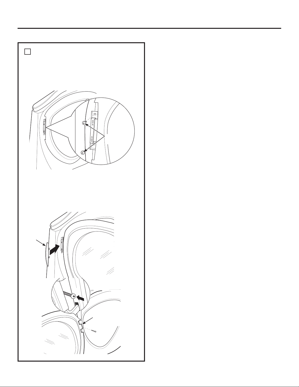
REVERSING THE DOOR SWING (if desired)
39
REINSTALL DOOR ASSEMBLY
Place the door back on the dryer front panel, making
sure the latch is engaged and the hinge is sitting in
the two openings in the dryer front. Assemble the
door to the front cabinet, using 2 screws (#10 x 0.75”
tapping screws).
Install 2 x B
screws
7
Install the new left-hand hinge cap (from the
reversibility kit) onto the hinge, by opening the
dryer door and screwing the hinge cap into place.
NOTE: Save the remaining caps and covers in
case you want to reverse the hinge again.
1 x C Screw
in hinge cap
Hinge cap
Installation Instructions
40
STACKING THE WASHER AND DRYER (if desired)
BEFORE YOU BEGIN
Read these instructions completely and carefully.
•
IMPORTANT – Save these instructions for
local electrical inspector’s use.
•
IMPORTANT – Observe all governing
codes and ordinances.
•
Note to Installer – Be sure to leave these
instructions with the Consumer.
•
Note to Consumer – Keep these instructions for
future reference.
•
Service must be performed by a qualified installer.
•
Proper installation is the responsibility of the
installer.
FOR YOUR SAFETY:
WARNING
• Electric Shock Hazard. Disconnect power before
installing. Failure to do so could result in serious
injury or death.
• Potential Personal Injury. More than two people
are recommended to lift the dryer into position
because of its weight and size. Failure to do so
could result in personal injury or death.
• Avoid Tipping and Rupture of Utility Services.
Dryer must be securely attached to the washer.
DO NOT place the washer on top of the dryer.
Failure to do so could result in personal injury/
death or property damage.
• Mobile Home or Manufactured Home Installation
– Stacking of a gas dryer is not permitted in a
mobile home or manufactured home.
MINIMUM CLEARANCE OTHER THAN
ALCOVE OR CLOSET INSTALLATION
Minimum clearance to combustible surfaces and
for air opening are: 0” both sides, 1” front and
3” rear. Consideration must be given to provide
adequate clearance for installation and service.
REQUIREMENTS FOR ALCOVE OR
CLOSET INSTALLATION
• Your dryer is approved for installation in an
alcove or closet, as stated on a label on the dryer
back.
•
The dryer MUST be vented to the outdoors. See
the EXHAUSTING THE DRYER section.
•
Minimum clearance between dryer cabinet and
adjacent walls or other surfaces is:
0” either side
3” front and rear
•
Minimum vertical space from floor to overhead
shelves, cabinets, ceilings, etc., is 52”.
•
Closet doors must be louvered or otherwise
ventilated and have at least 60 square inches
of open area equally distributed. If the closet
contains both a washer and a dryer, doors must
contain a minimum of 120 square inches of open
area equally distributed.
•
The closet should be vented to the outdoors to
prevent gas pocketing in case of gas in the supply
line.
•
No other fuel-burning appliance shall be installed
in the same closet with the dryer (gas models
only).
NOTE: WHEN THE EXHAUST DUCT IS LOCATED AT
THE REAR OF THE DRYER, MINIMUM CLEARANCE
FROM THE WALL IS 5.5 INCHES.
Installation Instructions
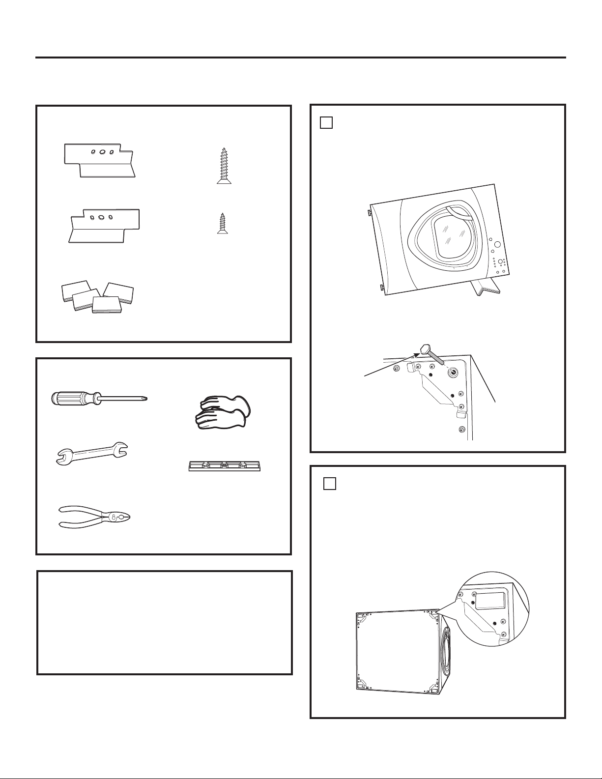
STACKING THE WASHER AND
DRYER (if desired) (cont.)
Installation Instructions
INSTALLATION PREPARATION
Remove the packaging.
Flatten the product carton to use as a pad to
lay the dryer down on its side. Continue using
the carton to protect the finished floor in front of
the installation location.
KIT GE FL STACK CONTENTS
Right hand bracket
Left hand bracket
4 rubber pads
4 #12 x 1” screws
4 #8 x 1/2” screws
TOOLS YOU WILL NEED
Phillips screwdriver
Open-ended wrench
Pliers
Gloves
Level
INSTALLING THE STACK BRACKET
KIT
REMOVE THE DRYER LEVELING LEGS
A. Carefully lay the dryer on its side. Use the packing
material so you don’t scratch the finish on the
dryer.
1
B. Use an open-end wrench or pliers to remove the
dryer leveling legs.
Back out and remove
all 4 leveling legs
INSTALL RUBBER PADS TO DRYER
BASE
Locate the 4 rubber pads in the parts package.
Remove the adhesive backing and firmly place
over on the bracket where you removed the
leveling legs.
2
41
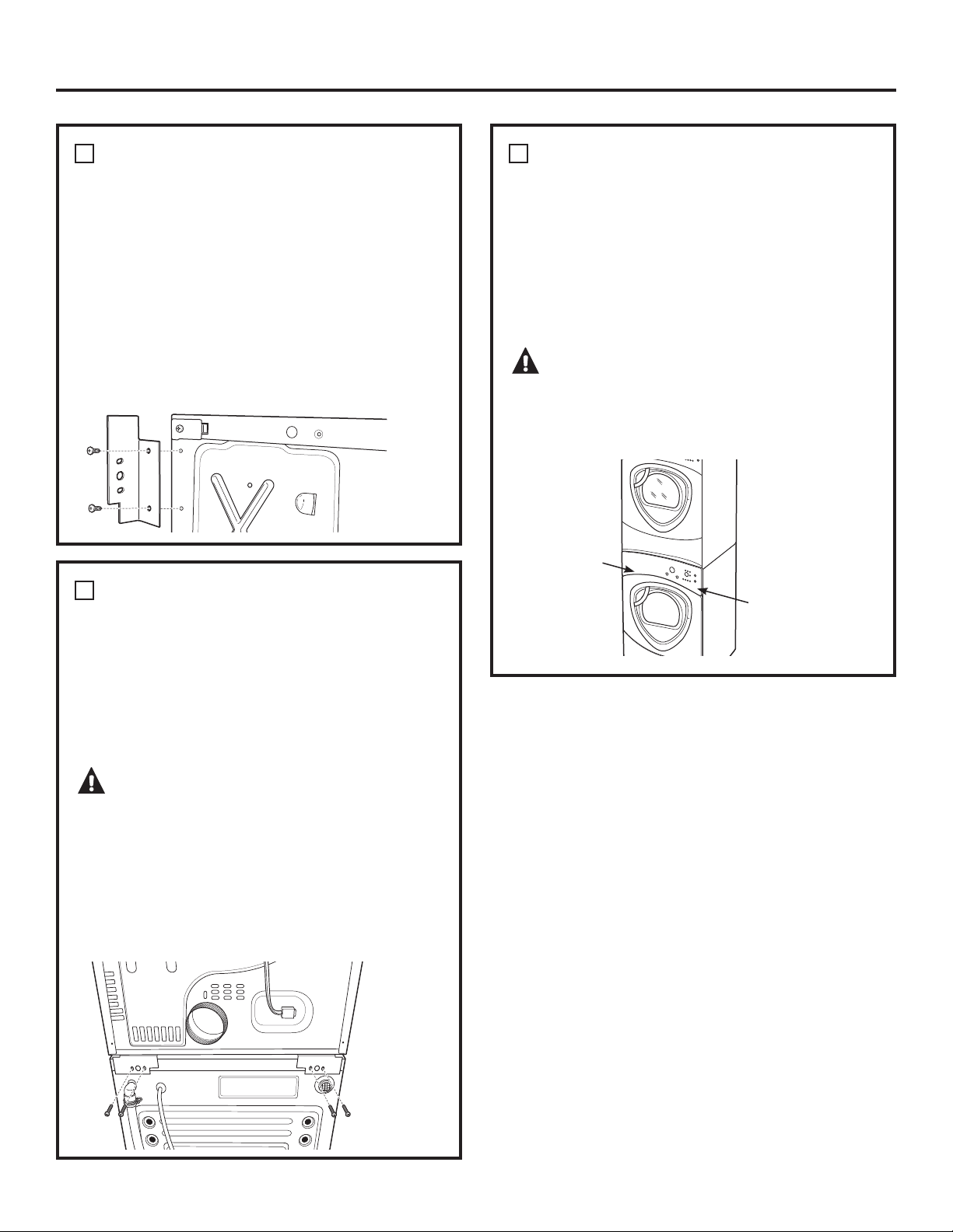
42
INSTALL BRACKET TO DRYER
A. Align the holes in the left bracket with the holes
in the bottom left corner of the dryer. Use a
Phillips screwdriver to install the 2 #12 x 1”
tapping screws.
B. Repeat the above step with the right bracket on
the bottom right corner of the dryer.
C. Set the dryer upright.
NOTE: Make sure to set the dryer on a piece of
packing material so the brackets that are attached
to the bottom of the dryer do not damage the floor.
3
INSTALL DRYER AND BRACKET ON
WASHER
A. Lift the dryer on top of the washer. Be careful
not to scratch the top of the washer with the
brackets. Protect the washer control panel with
cardboard or other protection. Be sure to lift the
dryer high enough to clear the washer control
panel.
WARNING – Potential Personal
Injury. More than two people are recommended
to lift the dryer into position because of its weight
and size. Failure to do so could result in personal
injury or death.
B. Align the holes in the bracket with the holes
in the back of the washer. Using a Phillips
screwdriver, attach the 2 #8 x 1/2” tapping
screws. Repeat on both sides of the washer
.
4
FINALIZE THE INSTALLATION
A. Refer to the washer Installation Instructions to
complete the washer installation.
B. Refer to the dryer Installation Instructions to
complete the dryer installation.
C. Carefully slide or walk the stacked washer and
dryer into place. Use felt pads or other sliding
device to assist moving and to protect flooring.
WARNING – Potential Personal
Injury. Do not push on the dryer once installed to
top of the washer. Pushing on the dryer may
result in pinched fingers.
5
Place
hands
here
Place
hands
here
Installation Instructions
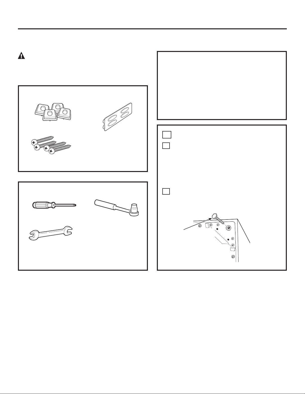
Installation Instructions
1
REMOVE THE LEVELING LEGS
A
Carefully lay the washer or dryer on its side to
access the leveling legs on the bottom of the
appliance.
IMPORTANT: Do not lay the washer or dryer on its
back! Do not remove the shipping bolts on the back
side of the washer. The bolts must remain in place
until the washer is returned to an upright position.
B
Use an open-end wrench to remove the washer
or dryer leveling legs.
INSTALLATION PREPARATION
Remove the packaging.
The drawer divider is taped at the top of the shipping
carton. Remove the divider and set aside for final
installation.
Flatten the product carton to use as a pad to lay
the washer or dryer down on its side. Continue using
the carton to protect the finished floor in front of the
installation location.
CAUTION ³'XHWRWKHVL]HDQGZHLJKWRI
these products, and to reduce the risk of personal
injury or damage to the product, TWO PEOPLE ARE
REQUIRED FOR PROPER INSTALLATION.
INSTALLING THE PEDESTAL (if desired)
KIT CONTENTS
4 Support pads
4 Mounting screws
Drawer divider
TOOLS YOU WILL NEED
Phillips-head
screwdriver
9/16” Open-end
wrench or adjustable
wrench
7 mm Socket wrench
Back out and remove
all 4 leveling legs
43
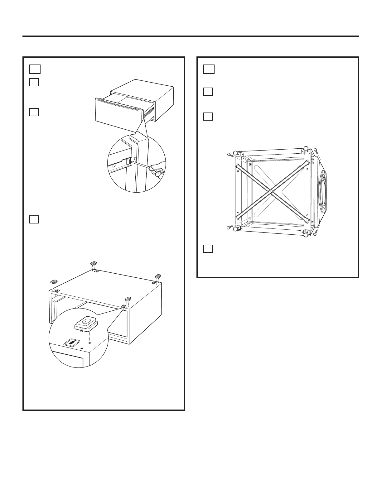
44
3
INSTALL THE PEDESTAL TO THE
WASHER OR DRYER
A
Place the pedestal against the bottom of the
unit. Check to be sure the drawer front is at the
front of the washer.
B
Align the holes in the pedestal with the holes in
the bottom of the unit. Use a Phillips screwdriver
to install the 4 bolts through the pedestal and
LQWRWKHXQLW³GRQRWWLJKWHQ
C
Slide the pedestal toward the unit, until it is
aligned front to back. Use a 7 mm socket
wrench to securely tighten the bolts.
2
PREPARE THE PEDESTAL
A
Pull the drawer
out as far as it
will go.
B
Remove
screws from
drawer slides.
Slide drawer
out of the
base and set
aside.
FOR DRYERS ONLY:
C
Locate the 4 support pads from the parts
package. Each pad has 2 protrusions that fit
into the holes on top of the pedestal. Press the
rubber pads into each set of corner holes on
the top of the pedestal as shown.
NOTE: The support pads should be installed on the
dryer only. DO NOT INSTALL THESE PADS ON THE
WASHER PEDESTAL.
Installation Instructions
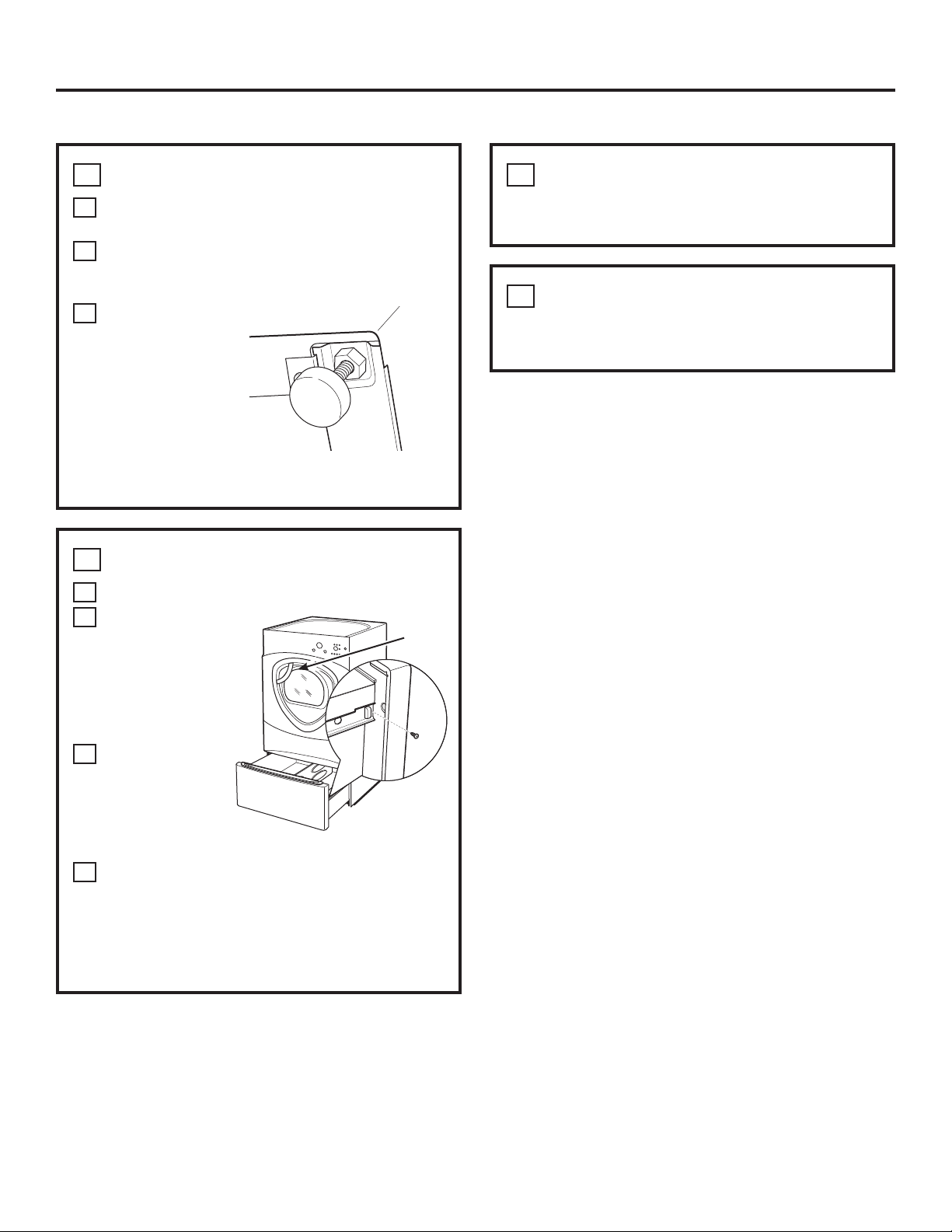
INSTALLING THE PEDESTAL (if desired) (cont.)
Installation Instructions
4
LEVEL THE WASHER OR DRYER
A
Stand the washer or dryer upright. Move it
close to its final location.
B
Make sure that the washer or dryer is level by
placing a level on top. Check side to side and
front to back.
C
Use an open
ended wrench
to adjust the
legs in and out.
Tighten the
lock nut against
the bottom of
the pedestal.
NOTE: To minimize vibration, the locking nuts must
be tight.
6
REMOVE SHIPPING SCREWS
Remove the 4 shipping screws on the back side of the
washer.
5
REINSTALL THE DRAWER
A
Check to be sure the slides are closed.
B
Slide the drawer
into the
opening. Align
the drawer
supports to the
slides on each
side.
C
Reinstall the
original screws
into each
drawer slide.
Tighten both
screws.
D
Open the drawer fully. Slide drawer divider
into slots in the center of the drawer. The
drawer should slide smoothly when you push
it closed.
7
FINALIZE THE INSTALLATION
Refer to the washer or dryer Installation Instructions
to complete the installation.
Drawer
Divider
45
46
Troubleshooting Tips
Save time and money! Review the charts on the following pages,
or visit GEAppliances.com. You may not need to call for service.
Before you call for service…
PROBLEM Possible Causes What To Do
Dryer shakes or Some shaking/noise is normal. • Move dryer to an even floor space, or adjust leveling legs
makes noise Dryer may be sitting unevenly as necessary until even.
Clothes take too long Improper or obstructed ducting • Check the Installation Instructions to make sure the
to dry dryer venting is correct.
• Make sure ducting is clean, free of kinks and
unobstructed.
• Check to see if outside wall damper operates easily.
Improper sorting • Separate heavy items from lightweight items (generally,
a well-sorted washer load is a well-sorted dryer load).
Large loads of heavy fabrics • Large, heavy fabrics contain more moisture and take
(like beach towels) longer to dry. Separate large, heavy fabrics into smaller
loads to speed drying time.
Controls improperly set • Match control settings to the load you are drying.
Lint filter is full • Clean lint filter before every load.
Blown fuses or tripped circuit • Replace fuses or reset circuit breakers. Since most
breaker dryers use 2 fuses/breakers, make sure both are
operating.
Overloading/combining loads • Do not put more than one washer load in the dryer at
a time.
Underloading • If you are drying only one or two items, add a few items
to ensure proper tumbling.
The DRY dryness level Load consists of a mixture • When combining heavy and light fabrics in a load,
was chosen but load is of heavy and light fabrics choose MORE DRY.
still damp
Exhaust system is blocked • Inspect and clean exhaust system.
Control pads not Controls accidentally put in • Press START/PAUSE.
responding service mode
Controls accidentally put in • Hold the LOCK button for 3 seconds to unlock the dryer.
lock mode
Controls performed an • Reset the in-house breaker.
incorrect operation
Dryer doesn’t start Control panel is “asleep” • This is normal. Press POWER to activate the control panel.
Dryer is unplugged • Make sure the dryer plug is pushed completely into
the outlet.
Fuse is blown/circuit breaker • Check the building’s fuse/circuit breaker box and
is tripped replace fuse or reset breaker. NOTE: Electric dryers
use two fuses or breakers.
Dryer was accidentally paused • If the light on the START/PAUSE button is flashing,
when starting Delay Start the dryer is paused. Press START/PAUSE to restart
the countdown.
No numbers displayed Dryer is continuously • This is normal. When the dryer senses a low level of
during cycle, only lights monitoring the amount of moisture in the load, the dryer will display the dry time
moisture in the clothes remaining.
47
Before you call for service… GEAppliances.com
PROBLEM Possible Causes What To Do
Time Remaining The estimated time may change • This is normal.
jumped to a when a smaller load than usual
lower number is drying
Cannot make a The DRYNESS LEVEL, TEMP • This is normal.
selection and the or OPTION that you are
dryer beeps twice trying to select is incompatible
with the chosen dry cycle
Dryer is running but The EXTEND TUMBLE • This is normal. During extended tumbling, the time
00 is displayed in option was chosen remaining is not displayed. The extended tumbling
Time Remaining option lasts approximately 20 minutes.
Clean Lint Filter (message) POWER button was activated • Press START/PAUSE to begin a dry cycle and the message
will disappear.
Dryer doesn’t heat Fuse is blown/circuit breaker • Check the building’s fuse/circuit breaker box and
is tripped; the dryer may tumble replace both fuses or reset both breakers. Your dryer
but not heat may tumble if only one fuse is blown or one breaker
tripped.
Gas service is off • Make sure gas shutoff at dryer and main shutoff are
fully open.
LP gas supply tank is empty • Refill or replace tank. Dryer should heat when utility
or there has been a utility service is restored.
interruption of natural gas
(gas models)
Inconsistent drying times Type of heat • Drying time will vary according to the type of heat used.
If you recently changed from an electric to a gas
(natural or LP) dryer, or vice versa, the drying time
could be different.
Type of load and • The load size, types of fabric, wetness of clothes and the
drying conditions length and condition of the exhaust system will affect
drying times.
Glow at the rear Heaters behind the drum • This is normal. Under certain drying conditions and
of the drum room ambient lighting, the glow of the heaters may be
visible at the rear of the drum.
Clothes are still wet The door was opened mid-cycle. • A dry cycle must be reselected each time a new load
and dryer shut off The load was then removed from is put in.
after a short time the dryer and a new load put in
without selecting a new cycle
Small load • When drying 3 items or less, choose SPEED DRY or
TIMED DRY.
Load was already dry except • Choose SPEED DRY or TIMED DRY to dry damp collars
for collars and waistbands and waistbands. In the future, when drying a load with
collars and waistbands, choose MORE DRY.
Dryer is not level • Move dryer to an even floor space or adjust leveling legs
as necessary until even.
Clothes are wrinkled Overdrying • Select a shorter drying time.
• Remove items while they still hold a slight amount of
moisture. Select a LESS DRY or DAMP setting.
Letting items sit in dryer after • Remove items when cycle ends and fold or hang
cycle ends immediately, or use the EXTEND TUMBLE option.
Overloading • Separate large loads into smaller ones.
PROBLEM Possible Causes What To Do
Clothes shrink Some fabrics will naturally shrink • To avoid shrinkage, follow garment care labels exactly.
when washed. Others can be
safely washed, but will shrink
• Some items may be pressed back into shape after drying.
in the dryer.
• If you are concerned about shrinkage in a particular
item, do not machine wash or tumble dry it.
Greasy spots on clothes Improper use of fabric softener • Follow directions on fabric softener package.
Drying dirty items • Use your dryer to dry only clean items. Dirty items can
with clean ones stain clean items and the dryer.
Clothes were not • Sometimes stains which cannot be seen when the
completely clean clothes are wet appear after drying. Use proper washing
procedures before drying.
Lint on clothes Lint filter is full • Clean lint screen before each load.
Improper sorting • Sort lint producers (like chenille) from lint collectors
(like corduroy).
Static electricity can attract lint • See suggestions in this section under STATIC.
Overloading • Separate large loads into smaller ones.
Paper, tissue, etc., left in pockets • Empty all pockets before laundering clothes.
Static occurs No fabric softener was used • Try a fabric softener.
• Bounce
®
Fabric Conditioner Dryer Sheets have been
approved for use in all GE Dryers when used in
accordance with the manufacturer’s instructions.
Overdrying • Try a fabric softener.
• Adjust setting to LESS DRY or DAMP.
Synthetics, permanent press • Try a fabric softener.
and blends can cause static
Collars and waistbands The dryness monitor senses • Choose SPEED DRY or TIMED DRY to dry damp collars
still wet at end of cycle that the body of the clothes and waistbands. In the future, when drying a load with
is dry collars and waistbands, choose MORE DRY.
Slight variation This is normal • Due to the metallic properties of paint used for this unique
in metallic color product, slight variations of color may occur due to
viewing angles and lighting conditions.
Door is too foggy to see Steam condenses on inner door • This is normal.
clothes during a steam
cycle
Water seen on inside of Steam condenses on these • This is normal.
door and top of lint filter surfaces
when opening door after
steam cycle
Small areas on clothes are Steam condenses on inner drum • Select a shorter cycle.
damp after steam cycle
Cycle or cycle time selected too • Manually reduce cycle time for given cycle.
long for size of load
Before you call for service…
48
PROBLEM Possible Causes What To Do
Small amount of water Inadequate load size for steam • Select a shorter cycle. Manually reduce cycle time
on floor in front of dryer cycle selected, excess steam for given cycle.
condenses inside cabinet and
leaks out
Water on floor in back Loose water hose connection to • Tighten connection.
of dryer valve
Hose missing rubber washer at • Install rubber washer provided with hose.
connection with valve
Dryer makes water Water valve is open filling steam • This is normal.
noises generator
Steam generator is dispensing • This is normal.
steam into drum
Water drips from door Steam condenses on inner door • This is normal.
when opened after
a Steam Cycle
Cannot see steam at Steam released at different • This is normal.
beginning of cycle
Cannot see steam at any The steam nozzle might be • CAll 800.GE.CARES to order nozzle replacement kit
time during cycle clogged with debris from your WE25M71 or to request a technician to replace this for you.
water supply
Garments still wrinkled Too many garments • Load fewer garments; manually increase time.
after steam cycle
Dryer continues to Extend Tumble was selected • Ensure Extend Tumble option is not selected.
tumble after display
says Complete
49
Before you call for service… GEAppliances.com
Service trips to your home to teach you how to use the
product.
Improper installation, delivery or maintenance.
Failure of the product if it is abused, misused or used for
other than the intended purpose or used commercially.
Replacement of the light bulb after its expected useful
life.
Replacement of house fuses or resetting of circuit breakers.
Damage to the product caused by accident, fire, floods or
acts of God.
Incidental or consequential damage caused by possible
defects with this appliance.
Damage caused after delivery.
Product not accessible to provide required service.
Defects or damage due to operation in freezing
temperatures.
Products which are not defective or broken, or which are
working as described in the Owner’s Manual.
What Is Not Covered (in the United States):
This warranty is extended to the original purchaser and any succeeding owner for products purchased for home use
within the USA. If the product is located in an area where service by a GE Authorized Servicer is not available, you
may be responsible for a trip charge or you may be required to bring the product to an Authorized GE Service location
for service. In Alaska, the warranty excludes the cost of shipping or service calls to your home.
Some states do not allow the exclusion or limitation of incidental or consequential damages. This warranty gives
you specific legal rights, and you may also have other rights which vary from state to state. To know what your legal
rights are, consult your local or state consumer affairs office or your state’s Attorney General.
Warrantor: General Electric Company. Louisville, KY 40225
All warranty service provided by our Factory Service Centers, or
an authorized Customer Care
®
technician. To schedule service,
on-line, visit us at GEAppliances.com, or call 800.GE.CARES
(800.432.2737).
Please have serial number and model number available when
calling for service.
Staple your receipt here.
Proof of the original purchase
date is needed to obtain
service under the warranty.
GE Dryer Warranty. (For customers in the United States)
(;&/86,212),03/,(':$55$17,(6³<RXUVROHDQGH[FOXVLYHUHPHG\LVSURGXFWUHSDLUDVSURYLGHGLQ
this Limited Warranty. Any implied warranties, including the implied warranties of merchantability or
fitness for a particular purpose, are limited to one year or the shortest period allowed by law.
For The Period Of: We Will Replace:
One Year Any part of the dryer which fails due to a defect in materials or workmanship. During this
From the date of the limited one-year warranty, GE will also provide, free of charge, all labor and related service costs
original purchase to replace the defective part.
Second Year Any part of the dryer which fails due to a defect in materials or workmanship. During this
From the date of the additional one-year limited warranty, you will be responsible for any labor or related service costs.
original purchase
Second through The extra-large or super-capacity dryer drum and main electronic control board if any of these
Fifth Year parts should fail due to a defect in materials or workmanship. During this additional four-year
From the date of the limited warranty, you will be responsible for any labor or related service costs.
original purchase
50
GE Dryer Warranty. (For customers in Canada)
All warranty service provided by our Factory Service Centres or an authorized technician.
For service, call 1.800.561.3344.
Please have serial number and model number available when calling for service.
Warrantor: MABE CANADA INC.
WARRANTOR IS NOT RESPONSIBLE FOR CONSEQUENTIALDAMAGES.
This warranty is extended to the original purchaser and any succeeding owner for products purchased in Canada
for home use within Canada. In-home warranty service will be provided in areas where it is available and deemed
reasonable by Mabe to provide.
(;&/86,212),03/,(':$55$17,(6³<RXUVROHDQGH[FOXVLYHUHPHG\LVSURGXFWUHSDLUDVSURYLGHGLQWKLV/LPLWHG
Warranty. Any implied warranties, including the implied warranties of merchantability or fitness for a particular purpose,
are limited to one year or the shortest period allowed by law.
Service trips to your home to teach you how to use the
product.
Improper installation, delivery or maintenance.
Failure of the product if it is abused, misused or used for
other than the intended purpose or used commercially.
Replacement of the light bulb after its expected useful
life.
Replacement of house fuses or resetting of circuit breakers.
Damage to the product caused by accident, fire, floods or
acts of God.
Incidental or consequential damage caused by possible
defects with this appliance.
Damage caused after delivery.
Product not accessible to provide required service.
Defects or damage due to operation in freezing
temperatures.
Products which are not defective or broken, or which are
working as described in the Owner’s Manual.
What Is Not Covered (in Canada):
51
For The Period Of: We Will Replace:
One Year Any part of the dryer which fails due to a defect in materials or workmanship. During this
From the date of the limited one-year warranty, GE will also provide, free of charge, all labor and related service costs
original purchase to replace the defective part.
Second Year Any part of the dryer which fails due to a defect in materials or workmanship. During this
From the date of the additional one-year limited warranty, you will be responsible for any labor or related service costs.
original purchase
Second through The extra-large or super-capacity dryer drum and main electronic control board if any of these
Fifth Year parts should fail due to a defect in materials or workmanship. During this additional four-year
From the date of the limited warranty, you will be responsible for any labor or related service costs.
original purchase
Consumer Support.
Parts and Accessories
GEApplianceparts.com
Individuals qualified to service their own appliances can have parts or accessories sent directly to their homes
(VISA, MasterCard and Discover cards are accepted). Order on-line today, 24 hours every day or by phone at
800.626.2002 during normal business hours.
If you need to order replacement parts, we recommend that you only use GE factory specified parts. These
parts are designed to work with your appliance and are manufactured and tested to meet GE specifications.
Instructions contained in this manual cover procedures to be performed by any user. Other servicing
generally should be referred to qualified service personnel. Caution must be exercised, since improper
servicing may cause unsafe operation.
GE Appliances Website GEAppliances.com
Have a question or need assistance with your appliance? Try the GE Appliances Website 24 hours a day,
any day of the year! For greater convenience and faster service, you can now download Owner’s Manuals,
order parts or even schedule service on-line.
Schedule Service GEAppliances.com
Expert GE repair service is only one step away from your door. Get on-line and schedule your service at
your convenience any day of the year! Or call 800.GE.CARES (800.432.2737) during normal business hours.
Real Life Design Studio GEAppliances.com
*(VXSSRUWVWKH8QLYHUVDO'HVLJQFRQFHSW³SURGXFWVVHUYLFHVDQGHQYLURQPHQWVWKDWFDQEHXVHGE\
people of all ages, sizes and capabilities. We recognize the need to design for a wide range of physical and
mental abilities and impairments. For details of GE’s Universal Design applications, including kitchen design
ideas for people with disabilities, check out our Website today. For the hearing impaired, please call 800.
TDD.GEAC (800.833.4322).
Extended Warranties GEAppliances.com
Purchase a GE extended warranty and learn about special discounts that are available while your warranty
is still in effect. You can purchase it on-line anytime, or call 800.626.2224 during normal business hours. GE
Consumer Home Services will still be there after your warranty expires.
Contact Us GEAppliances.com
If you are not satisfied with the service you receive from GE, contact us on our Website with all the details
including your phone number, or write to: General Manager, Customer Relations
GE Appliances, Appliance Park
Louisville, KY 40225
Register Your Appliance GEAppliances.com
5HJLVWHU\RXUQHZDSSOLDQFHRQOLQH³DW\RXUFRQYHQLHQFHTimely product registration will allow for
enhanced communication and prompt service under the terms of your warranty, should the need arise.
You may also mail in the pre-printed registration card included in the packing material.
52

53
Mesures de sécurité ....... 53–55
Foncionnement
Appareil intelligent ..................64
Caractéristiques. . . . . . . . . . . . . . . . .61, 62
Guide de démarrage ................56
Option réglage ......................61
Options de cycle ................60, 61
Panneau de contrôle ............56–59
Utilisation de la sécheuse ..........62
Installation
Avant de commencer ...........65, 66
Branchement des boyaux
d‘arrivée ............................68
Emplacement
de votre sécheuse ..............66, 67
Évacuation de la sécheuse .....76–82
Installation du socle .............94–96
Installation finale ....................83
Inversion de l’ouverture
de la porte ......................84–90
Raccordement
d’une sécheuse à gaz ...........69–72
Raccordement
d’une sécheuse électrique ......73–75
Superposer la sécheuse
à la laveuse ....................91–93
Conseils de dépannage . . 97–100
Soutien au consommateur
Garantie (Canada) ................ 102
Garantie (É
tats-Unis) ............. 101
Soutien au
consommateur ................... 103
Inscrivez ici les numéros de
modèle et de série :
Modèle N° ________________
Série N° __________________
Ces informations figurent sur
l’étiquette située à l’avant de la
sécheuse, derrière la porte.
CONSERVEZ CES DIRECTIVES
Mettez l’appareil à la terre conformément à tous les codes et
règlements en vigueur. Suivez les Directives d’installation.
Installez ou entreposez l’appareil dans une pièce où la
température est supérieure à 0°C, et où il sera à l’abri des
intempéries.
Branchez l’appareil sur un circuit protégé et de capacité
appropriée afin d’éviter toute surcharge électrique.
Retirez tous les articles d’emballage tranchants et jetez tous
les matériaux de transport.
Conduit d’évacuation:
1
L’air des sécheuses DOIT être évacué à l’extérieur pour
empêcher que de grandes quantités d’humidité et de
charpie soient envoyées dans la pièce.
2
Utilisez uniquement un conduit rigide en métal de 10 cm de
diamètre à l’intérieur du placard de la sécheuse. Utilisez
uniquement une un conduit métallioque de 10 cm de
diamètre flexible ou rigide agréée UL pour l’échappement
vers l’extérieur. N’utilisez jamais de un conduit facile à
perforer, en plastique ou autre matériau combustible.
L’UTILISATION D’UN CONDUIT EN PLASTIQUE OU EN UN
AUTRE MATÉRIEL COMBUSTIBLE PEUT CAUSER UN
INCENDIE. LE CONDUIT PERFORÉ PEUT CAUSER UN
INCENDIE S’IL S’EFFONDRE OU SE BOUCHE AU COURS DE
L’UTILISATION OU DE L’INSTALLATION.
Pour des détails complets, suivez les Instructions d’installation.
MESURES DE SÉCURITÉ IMPORTANTES.
LISEZ D’ABORD TOUTES LES DIRECTIVES.
AVERTISSEMENT!
Pour votre sécurité, suivez les directives fournies dans le présent manuel afin de
minimiser les risques d’incendie, d’explosion et de chocs électriques et prévenir des
dégâts matériels et des blessures graves ou mortelles.
SI VOUS REMARQUEZ UNE ODEUR DE GAZ :
1
N’allumez pas d’allumette ou de cigarette,
ou ne faites fonctionner aucun appareil à
gaz ou électrique.
2
N’actionnez aucun interrupteur; n’utilisez
aucun téléphone dans votre édifice.
3
Évacuez la pièce, l’édifice ou les environs.
4
Appelez immédiatement votre fournisseur
de gaz en utilisant le téléphone d’un
voisin. Suivez les directives qu’il vous
donnera.
5
Si vous ne pouvez joindre votre fournisseur
de gaz, appelez les pompiers.
Loi californienne sur le contrôle des substances toxiques et de l’eau potable
Cette loi exige que le gouverneur de Californie publie une liste de substances reconnues par l’état comme étant cancérigènes,
responsables de malformations congénitales ou des autres effets nuisibles sur les organes reproducteurs, et que les entreprises
avertissent les clients de l’exposition potentielle à ces substances.
Les appareils ménagers fonctionnant au gaz peuvent causer une exposition mineure à quatre de ces substances, à savoir le
benzène, le monoxyde de carbone, le formaldéhyde et la suie, principalement en raison de la combustion incomplète du gaz
naturel ou du gaz de pétrole liquéfié.
Le réglage adéquat de la sécheuse réduira au maximum la combustion incomplète. L’exposition à ces substances peut être
encore réduite davantage en assurant une évacuation adéquate de la sécheuse vers l’extérieur.
UNE INSTALLATION ADÉQUATE
Avant d’utiliser votre sécheuse, assurez-vous qu’elle a été adéquatement installée, conformément
aux Instructions d’installation. Les consignes d’installation figurent au dos de ce manuel.
N’entreposez pas ou n’utilisez pas
d’essence ou autres vapeurs ou liquides
inflammables à proximité de cet appareil
ou de tout autre électroménager.
L’installation et les réparations doivent
être effectuées par un installateur qualifié,
une entreprise de réparation ou votre
fournisseur de gaz.
54
55
AVERTISSEMENT!
AUTOUR DE VOTRE SÉCHEUSE
Conservez la zone sous et autour de vos appareils libre de
tous matériaux combustibles (charpies, papiers, chiffons,
etc.), essence, produits chimiques et autres gaz et liquides
inflammables.
Gardez le sol propre et sec à proximité de vos
électroménagers afin de ne pas glisser.
Il faut exercer une étroite surveillance lorsque vous faites
fonctionner cet appareil en présence d’enfants. Ne les
laissez pas jouer sur, avec ou dans cet appareil ou dans
tout autre appareil.
Assurez-vous qu’il n’y ait aucune accumulation de charpie,
de poussière ou de saleté autour et à proximité de l’orifice
d’évacuation.
Gardez tous les produits pour la lessive (comme les
détersifs, les javellisants, etc.) hors de la portée des enfants,
de préférence dans une armoire fermée à clef. Suivez
toutes les mises en garde sur les étiquettes pour éviter des
blessures.
Ne montez jamais sur le dessus de la sécheuse.
LORSQUE VOUS UTILISEZ LA SÉCHEUSE
Ne vous penchez jamais dans la sécheuse pendant que
le tambour tourne. Avant de charger ou de décharger la
sécheuse ou d’y ajouter des vêtements, attendez que le
tambour se soit complètement arrêté.
Avant chaque séchage, nettoyez le filtre à charpie afin
de prévenir l’accumulation de charpie à l’intérieur de la
sécheuse ou dans la pièce. NE FAITES PAS FONCTIONNER
LA SÉCHEUSE SANS LE FILTRE À CHARPIE.
Ne lavez pas ou ne faites pas sécher des articles qui ont
été lavés avec des produits combustibles ou explosifs,
ou qui ont été trempés dans ces produits ou qui en sont
tachés (cire, peinture, huile, essence, dégraissants, solvants
pour le nettoyage à sec, kérosène, etc.). Ces substances
émettent des vapeurs qui peuvent prendre feu ou exploser.
Ne versez pas ces substances dans l’eau de la laveuse.
N’utilisez pas ces substances à proximité de votre laveuse
ou de votre sécheuse pendant qu’elles fonctionnent.
Ne rangez pas dans votre sécheuse des articles qui ont
été en contact avec des huiles de cuisson; ceux-ci peuvent
provoquer une réaction chimique susceptible de faire
s’enflammer vos vêtements.
Il ne faut pas mettre dans la sécheuse, ou à proximité
de celle-ci, tout article ayant été utilisé avec un solvant
dégraissant ou contenant une substance inflammable
(comme des chiffons de nettoyage, des vadrouilles, des
serviettes utilisées dans les salons de coiffure, etc.), à
moins qu’ils aient été débarrassés de toute trace et de
toute vapeur de substance inflammable. On utilise à la
maison de nombreux produits inflammables: acétone,
alcool dénaturé, essence, kérosène, nettoyants ménagers,
détachants, térébenthine, cire, décapants, contenant du
distillat de pétrole.
La lessive peut atténuer les propriétés ignifugeantes des
tissus. Pour éviter cette situation, suivez à la lettre les
directives données par le fabricant du vêtement.
Ne faites pas sécher des articles contenant du caoutchouc,
du plastique, de la mousse ou autres matériaux similaires
(comme des soutiens-gorge préformés, des chaussures de
tennis, des caoutchoucs, des tapis de bain, des carpettes,
des bavoirs, des culottes de bébé, des sacs de plastique,
des oreillers, etc.), car ces matériaux peuvent fondre ou
brûler. De plus, dans certaines circonstances, certains
matériaux de caoutchouc peuvent causer un incendie par
combustion spontanée lorsqu’ils sont chauffés.
Ne rangez pas des articles qui peuvent fondre ou brûler,
comme du plastique, du papier, ou des vêtements sur le
dessus de la sécheuse pendant qu’elle fonctionne.
Les vêtements portant la mention «Faire sécher loin de la
chaleur» ou «Ne pas faire sécher par culbutage» (comme
les gilets de sauvetage contenant du Kapok) ne doivent pas
être séchés dans votre sécheuse.
Ne faites pas sécher d’articles en fibre de verre dans votre
sécheuse. Les particules qui restent dans la sécheuse et
qui pourraient être recueillies par les vêtements lors d’un
séchage subséquent risquent de causer des irritations
cutanées.
Pour réduire les risques de chocs électriques, débranchez
toujours l’appareil ou coupez l’alimentation électrique au
panneau de distribution en enlevant le fusible ou en
déclenchant le disjoncteur avant de le réparer ou de le
nettoyer (sauf pour enlever et nettoyer le filtre à charpie).
REMARQUE: Le fait d’appuyer sur START/PAUSE (MISE EN
MARCHE/PAUSE) ou POWER (ALIMENTATION) NE coupe
PAS l’alimentation électrique à l’appareil.
Si vous apercevez de l’eau sur le plancher autour de la
sécheuse, appelez le service à la clientèle.
N’obstruez pas le flux de l’air de ventilation. N’empilez
pas, ne placez pas du linge ou des tapis devant ou à
l’arrière de la sécheuse.
MESURES DE SÉCURITÉ IMPORTANTES.
LISEZ D’ABORD TOUTES LES DIRECTIVES.
www.electromenagersge.ca
LORSQUE VOTRE SÉCHEUSE N’EST PAS EN MARCHE
Lorsque vous débranchez l’appareil, tirez sur la fiche
et non pas sur le cordon afin d’éviter d’endommager
le cordon d’alimentation. Installez le cordon de sorte
que personne ne marche ou ne trébuche dessus, ou
qu’il ne soit pas exposé à des dommages.
Ne réparez ou ne remplacez aucune pièce de cet
appareil, à moins que cela ne soit spécifiquement
recommandé dans le présent manuel ou dans des
directives de réparation que vous comprenez et que
vous êtes en mesure de suivre.
Avant de jeter ou d’entreposer une sécheuse, enlevez
toujours la porte afin d’empêcher les enfants de se
cacher à l’intérieur.
Ne trafiquez pas les commandes de l’appareil.
VEUILLEZ LIRE ET SUIVRE ATTENTIVEMENT CES MESURES DE
SÉCURITÉ.
CONSERVEZ CES DIRECTIVES
56
AVERTISSEMENT!
LORSQUE VOUS UTILISEZ LA SÉCHEUSE (SUITE)
Ne faites pas fonctionner l’appareil s’il est endommagé,
défectueux, partiellement démonté ou si des pièces
sont manquantes ou défectueuses, ou si le cordon
d’alimentation ou la fiche sont endommagés.
L’intérieur de l’appareil et le raccord du conduit
d’évacuation à l’intérieur de la sécheuse doivent être
nettoyés une fois par an par une personne qualifiée.
Voyez les Conseils pour le tri et le chargement en page
62.
Si votre sécheuse fonctionne au gaz, elle est pourvue
d’un système d’allumage électrique automatique et
ne possède pas de veilleuse. N’ESSAYEZ PAS DE
L’ALLUMER AVEC UNE ALLUMETTE. Vous risquez de
vous brûler si vous approchez votre main du brûleur
et que le dispositif d’allumage automatique s’allume.
Ne pas ouvrir la porte de la sécheuse durant les
cycles de vapeur. La vapeur est très chaude, et
continuera de s’échapper du port plusieurs secondes
après l’ouverture de la porte. Ne pas toucher le port de
vapeur après un cycle de vapeur.
Ne pas utiliser le cycle vapeur avec des items tel
que: laine, cuir, soie, lingerie, produits mousse ou
couvertures électriques.
Ne pas utiliser les cycles vapeur avec les nouveaux
vêtements sans un premier lavage.
Il est possible que vous désiriez assouplir votre lessive
ou réduire le collement électrostatique en utilisant
un assouplissant textile dans votre sécheuse ou un
produit antistatique. Nous vous recommandons
d’utiliser un assouplissant liquide au cours du
programme de lavage, conformément aux directives
du fabricant de ce type de produit, ou de faire l’essai
d’un assouplissant textile pour la sécheuse, pour lequel
le fabricant certifie sur l’emballage que son produit
peut être utilisé en toute sécurité dans la sécheuse.
La responsabilité des problèmes de rendement ou
de fonctionnement qui ne sont pas couverts par
la garantie de cet appareil et sont attribuables à
l’utilisation de ces produits relève du fabricant de ces
produits.
Ne jamais tenter d’utiliser les cycles Steam Dewrinkle
(Vapeur Anti Froissage) ou Steam Refresh (Vapeur
Rafraîchissante) sans vêtements dans le tambour. De
plus, il est hautement recommandé de sélectionner
la bonne taille de brassée pour de meilleurs résultats.
Sélectionner des cycles pour de grosses brassées pour
des petites brassées pourrait mouiller les vêtements et
sélectionner des cycles de petites brassées pour des
grosses brassées pourrait résulter en une mauvaise
performance d’anti froissage.
Ne pulvérisez jamais tout type d’aérosol dans, sur
ou à coté de la sécheuse. N’utilisez aucun type
de nettoyant en atomiseur quand vous nettoyez
l’intérieur de la sécheuse. Des fumes dangereuses ou
un choc électrique pourraient se produire.
MESURES DE SÉCURITÉ IMPORTANTES.
LISEZ D’ABORD TOUTES LES DIRECTIVES.
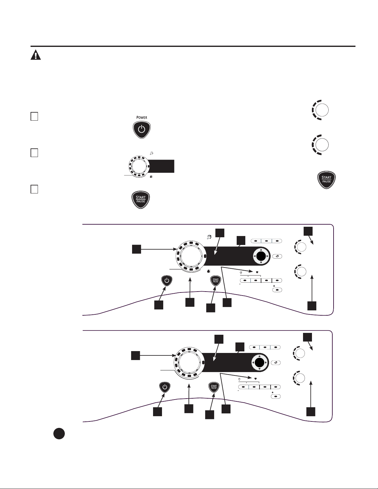
AVERTISSEMENT! Afin de réduire le risque d’incendie, de décharge électrique, ou de blessure,
lisez les MESURES DE SÉCURITÉ IMPORTANTES avant de mettre cet appareil en
marche.
À propos du panneau de contrôle de la sécheuse.
www.electromenagersge.ca
Dans ce manuel, les caractéristiques et l’apparence peuvent varier selon votre modèle.
Démarrage
Si l’écran est noir, appuyez sur la touche POWER
(ALIMENTATION) afin de réactiver l’affichage.
1
Appuyez sur
la touche POWER
(ALIMENTATION)
.
2
Sélectionnez un cycle en
tournant
le bouton
Cycle.
3
Si vous avez sélectionné SENSOR
CYCLE (CYCLE PAR CAPTEUR) –
appuyez simplement sur
la touche
START/PAUSE (MISE EN MARCHE/
PAUSE).
Si vous avez sélectionné TIMED DRY
CYCLE (CYCLE DE SÉCHAGE MINUTÉ)
– sélectionnez le réglage de chaleur
et la durée que vous désirez pour le
séchage de vos articles en utilisant les
touches du curseur. Appuyez ensuite
sur la touche START/PAUSE (MISE EN
MARCHE/PAUSE).
57
STEAMREFRESH
SPEED DRY
WARM UP
ACTIVE WEAR
WRINKLE FREE
DELICATES
NORMAL /
MIXED LOADS
SENSOR DRY
TIME DRY
COTTONS
SPECIALTY
CYCLES
TIMED DRY
STEAM
DEWRINKLE
HIGH
MEDIUM
LOW
EXTRA LOW
ANTI -
BACTERIAL
DRY
TEMP
SENSOR
DRY
MORE DRY
DRY
LESS DRY
DAMP
EXTRA DRY
Power (alimentation)
Appuyez sur cette touche pour « allumer » l’écran. Si l’écran est actif, appuyez pour éteindre la sécheuse.
REMARQUE: Le fait d’appuyer sur POWER (ALIMENTATION) ne coupe pas l’alimentation électrique à
l’appareil.
1
ENTER
HIGH
MEDIUM
LOW
EXTRA LOW
ANTI -
BACTERIAL
DRY
TEMP
SENSOR
DRY
MORE DRY
DRY
LESS DRY
DAMP
EXTRA DRY
POWER
DELAY
STAR T
Push to Lock Control
Hold 3 Secs to Unlock
e
DRY
DRYER
RACK
LOCK
BACKBACK
SPECIALTY
CYCLES
PRESS & HOLD 3 seconds for secondary OPTIONS
STORE MY CYCLE
EXTENDED
TUMBLE
DRUM
LIGHT
SETTINGS
MY
CYCLE
DAMP
ALERT
STEAMREFRESH
SPEED DRY
WARM UP
ACTIVE WEAR
WRINKLE FREE
DELICATES
NORMAL /
MIXED LOADS
SENSOR DRY
TIME DRY
TIMED DRY
STEAM
DEWRINKLE
COTTONS
1
2
3
4
5
6
7
8
9
Modèles : PFDS450 / PFDS455 / PFMS450 / PFMS455
ENTER
H
IGH
MEDIUM
LOW
EXTRA LOW
ANTI -
BACTERIAL
DRY
TEMP
SENSOR
DRY
MORE DRY
D
RY
LESS DRY
DAMP
EXTRA DRY
POWER
DELAY
STAR T
Push to Lock Control
Hold 3 Secs to Unlock
e
DRY
DRYER
RACK
LOCK
BACKBACK
SPECIALTY
CYCLES
PRESS & HOLD 3 seconds for secondary OPTIONS
STORE MY CYCLE
EXTENDED
TUMBLE
DRUM
LIGHT
SETTINGS
MY
CYCLE
DAMP
ALERT
SPEED DRY
ACTIVE WEAR
WRINKLE FREE
DELICATES
NORMAL /
MIXED LOADS
COTTONS
SENSOR DRY
TIME DRY
DEWRINKLE
WARM UP
TIMED DRY
AIR FLUFF
NO HEAT
Models: PFDN440 / PFDN445 / PFMN440 / PFMN445
1
2
3
4
5
6
7
8
9
2
A propos du panneau de contrôle de la sécheuse.
Dry Cycles (cycles de séchage)
Le cycle de séchage contrôle la durée du processus de séchage. Le tableau ci-dessous vous aidera à trouver le bon réglage
de séchage en fonction de votre brassée.
Cycles par capteur
COTTONS (cotons) Pour les cotons et la plupart des articles en toile.
NORMAL/ Pour les brassées constituées de cotons et de mélanges de polyester.
MIXED LOAD
(charge normale/
mixte)
WRINKLE FREE Pour les articles infroissables/entretien facile et sans repassage.
(infroissables)
ACTIVE WEAR Pour les vêtements de sports, d’exercice et certains vêtements décontractés. Les tissus
(vêtements bénéficient de finitions en nouvelle technologie et sont composés de fibres élastiques
de sport) comme le Spandex.
DELICATES Pour la lingerie et les tissus délicats.
(délicats)
SPEED DRY Pour les petites brassées qui doivent être séchées rapidement, comme les tenues de
(séchage rapide) sport ou les uniformes d’école. Ce cycle peut aussi être utilisé si le cycle précédent a laissé quelques
articles encore humides, comme des cols ou des ceintures.
Timed Dry Cycles (cycles de séchage minuté)
STEAM Pour des vêtements secs légèrement froissés. Réduit de façon significative les plis sur 1 à 5
REFRESH vêtements. Sélectionnez un plus grand nombre de vêtements pour le cycle (par exemple,
(vapeur sélectionner une brassée de 5 morceaux de vêtements pour une brassée de 1 morceaux de
rafraîchissante) vêtement) pourrait mouiller les vêtements. Après le Cycle SteamRefresh, l’unité émettra un
(sur certains bip et affichera “Garments Ready” (Vêtements Prêts) et « 0 :00 ». Si l’unité n’est pas fermée
modèles) ou si la porte n’est pas ouve rte, la sécheuse continuera le culbutage pendant 30 minutes.
À la fin des 30 minutes, il sera affiché « 0 :00 » et « Cycle Complete » (« 0 :00 » et
« Cycle terminé »).
REMARQUE: Lorsque STEAM REFRESH (Rafraîchissement à la vapeur) est sélectionné,
EXTENDED TUMBLE (culbutage prolongé) s’active automatiquement et ne peut pas être
désactivé.
Un seul article de tissu extrêmement léger peut nécessiter d’ajouter un article supplémentaire au
cycle de vapeur rafraîchissante pour atteindre des résultats optimaux.
DEWRINKLE Pour défroisser des articles secs ou légèrement humides. Ce cycle n’est pas recommandé pour les
(Défroissage) tissus délicats.
(sur certains
modèles)
STEAM DEWRINKLE Pour utiliser avec des brassées plus grosses que le STEAM REFRESH. Idéal pour des brassées
(défroisser) de vêtements qui ont été laissées dans la sécheuse pendant une longue période de temps.
(sur certains Sélectionnez un cycle plus important que nécessaire (par exemple, sélectionner Grosse
modèles) Brassée pour une sécheuse à moitié pleine) pourrait mouiller les vêtements.
WARM UP Fournit 10 minutes de préchauffage des vêtements.
(préchauffage)
My Cycle (mon cycle) (sur certains modèles)
MY CYCLE Appuyez sur cette touche pour créer, modifier ou utiliser des cycles de séchage
(mon cycle) personnalisés.
Timed Dry (séchage minuté)
Cette commande permet de définir son propre temps de séchage. La fonction TIMED DRY (SÉCHAGE MINUTÉ) est aussi
recommandée pour les petites brassées.
Pour utiliser TIMED DRY (SÉCHAGE MINUTÉ) :
1. Tournez le cadran du cycle de séchage sur TIMED DRY.
2.
Sélectionnez le temps de séchage en appuyant sur les touches
S et T. Vous pouvez augmenter
la durée par intervalle de 10 minutes, et ce jusqu’à 2 heures et demie.
3. Sélectionnez la température de séchage (DRY TEMP).
4. Fermez la porte.
5. Appuyez sur START/PAUSE (MISE EN MARCHE/PAUSE).
Sensor Dry Level (détection du niveau d’humidité)
Le détecteur surveille en permanence le niveau d’humidité dans le linge. Quand l’humidité dans vos vêtements atteint le
niveau de séchage que vous avez choisi, la sécheuse s’arrête.
EXTRA DRY Utilisé pour les tissus résistants ou les articles qui ont besoin d’être très secs,
(extra sec) comme par exemple les serviettes.
MORE DRY (plus sec) Utilisé pour les types de tissus lourds ou mélangés.
DRY (sec) Utilisé pour un niveau de séchage normal adapté à la plupart des brassées. C’est le cycle
recommandé pour un fonctionnement en économie d’énergie.
LESS DRY (moins sec) Utilisé pour les tissus plus légers (idéal pour le repassage).
DAMP (humide) Pour laisser les articles partiellement humides.
3
4
58
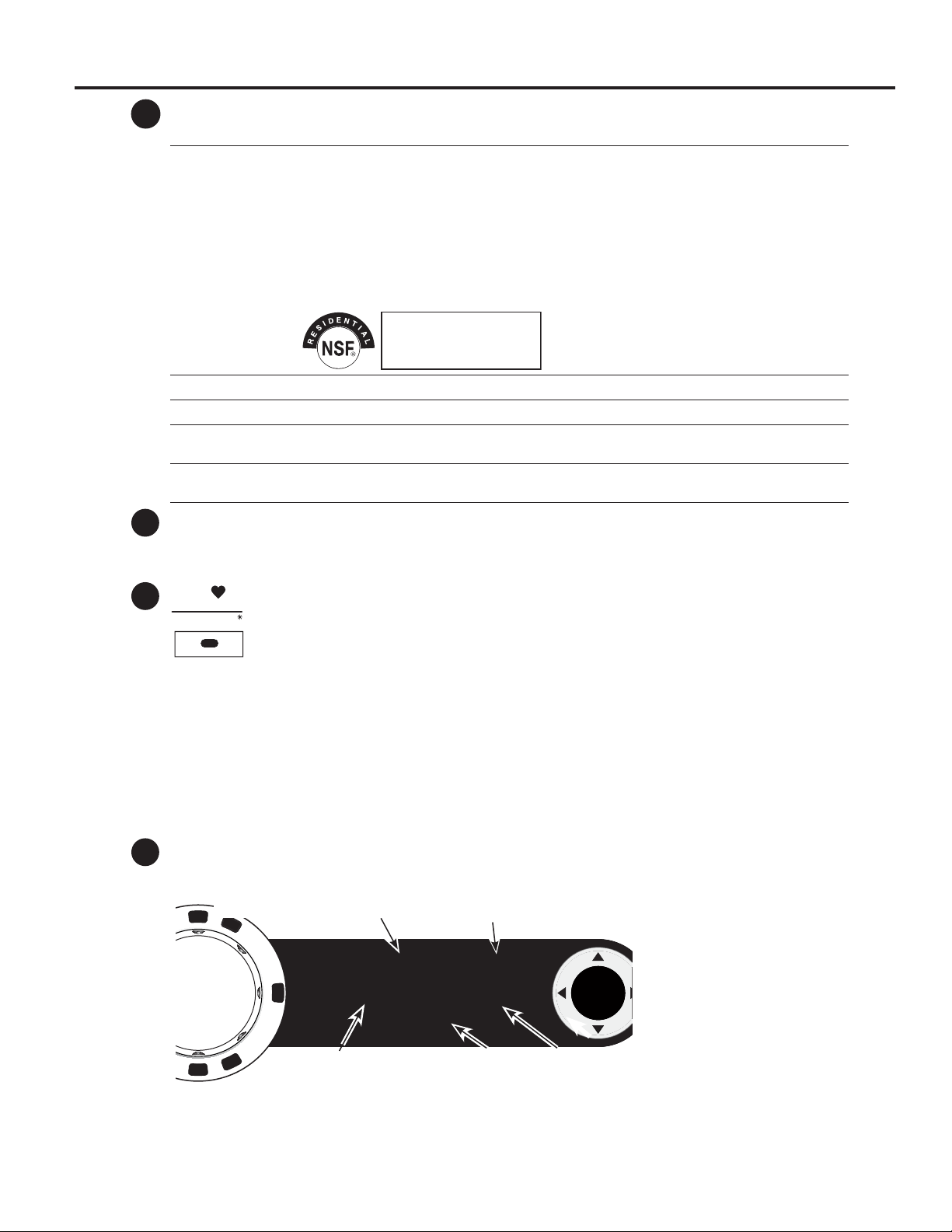
59
www.electromenagersge.ca
Dry Temp (température de séchage)
Vous pouvez modifier la température de votre cycle de séchage.
ANTI-BACTERIAL Cette option peut uniquement être utilisée avec les cycles COTTONS (COTONS) ou MIXED
(anti-bactérien) LOAD (CHARGE MIXTE). Cette option permet de diminuer de 99,9 % la possibilité que
certains types de bactéries soient présentes, parmi lesquelles : Staphylococcus aureus,
Pseudomonas aeruginosa et Klebsiella pneumoniae*. Le processus antibactérien se produit
quand des températures élevées sont mises en oeuvre pendant une partie de ce cycle de
séchage.
REMARQUE : N’utilisez pas ce cycle pour des tissus délicats.
* Le cycle antibactérien (Anti-Bacterial) est certifié par NSF International (autrefois
appelé National Sanitation Foundation) conformément au Protocol P154 de NSF sur les
performances sanitaires des sécheuses domestiques.
HIGH (haute) Pour les cotons normaux à lourds.
MEDIUM (moyenne) Pour les synthétiques, les mélanges et les articles étiquetés sans repassage.
LOW (basse) Pour les tissus délicats, synthétiques et les articles étiquetés Tumble Dry Low (séchage par
culbutage à basse température).
EXTRA LOW Pour la lingerie et les tissus délicats.
(extra basse)
START/PAUSE (MISE EN MARCHE/PAUSE)
Appuyez sur cette touche pour lancer un cycle de séchage. Si la sécheuse est déjà en fonctionnement, le fait
d’appuyer sur cette touche interrompt le cycle en cours. Appuyez encore sur la touche pour reprendre le cycle
de séchage.
My Cycle (mon cycle) (sur certains modèles)
Configurez votre propre combinaison de réglages et enregistrez-la ici pour ensuite la lancer d’une
touche. Cette configuration personnalisée peut être définie pendant qu’un cycle est en cours.
Pour enregistrer une combinaison de réglages MY CYCLE (MON CYCLE).
1. Sélectionnez un cycle de séchage.
2. Changez les réglages DRY TEMP et SENSOR DRY LEVEL afin de répondre à vos besoins.
3. Sélectionnez toutes les OPTIONS de séchage souhaitées.
4. Appuyez sur la touche MY CYCLE (MON CYCLE) et maintenez-la enfoncée pendant trois secondes pour
sauvegarder votre sélection. Un bip sonore retentit, le bouton s’allume et le module affiche “My cycle is now
programed with the current cycle settings” (mon cycle est maintenant programmé avec les réglages de cycle
actuels).
Pour lancer votre combinaison MY CYCLE (MON CYCLE) enregistrée :
Appuyez sur la touche MY CYCLE (MON CYCLE) avant de sécher une brassée. La lumière autour de la touche
s’illuminera quand MY CYCLE (MON CYCLE) est sélectionné.
Pour modifier votre combinaison MY CYCLE (MON CYCLE) enregistrée.
Suivez les étapes 1 à 4 dans la section « Pour enregistrer une combinaison de réglages MY CYCLE (MON CYCLE) ».
Display (affichage)
«
CLEAN LINT FILTER » (Nettoyer le filtre à charpie) (message)
Ce message s’affiche régulièrement. Ce n’est qu’un rappel.
5
6
8
7
Protocole P154 de NSF
sur les performances sanitaires
des sécheuses domestiques
STORE MY CYCLE
MY
CYCLE
ENTER
SPECIALTY
CYCLES
SPECIALTY CYCLE 1:10
Comforters
Delay Time 1:00
Clean Lint Filter
0
Statut du cycle spécial OU Grill de
séchage OU Séchage minuté
Durée de cycle estimée OU
durée de séchage restante
Statut du délai
d’attente
Affichage du statut
du filtre à charpie
DÉLAI
D’ATTENTE
Après avoir appuyé sur le bouton
POWER, le message CLEAN
FILTER pourrait apparaitre si le
cycle antérieur n’avait pas fini. Ce
message disparaitra après avoir
appuyé sur le bouton START.
Même si vous avez déjà nettoyé
le filtre (avant d’appuyer sur
le bouton POWER) le message
CLEAN LINT FILTER sera encore
affiché jusqu’à ce que le bouton
START soit activé.

60
A propos du panneau de contrôle de la sécheuse.
Specialty Cycles (cycles spéciaux)
1. Tournez le bouton CYCLE sur SPECIAL CYCLES. Une liste d’options de cycle apparaîtra à l’écran.
2. Sélectionnez une CATEGORY (CATÉGORIE) en appuyant les touches de curseur.
3. Sélectionnez un CYCLE en appuyant les touches de curseur.
Appuyez sur la touche BACK (RETOUR) pour retourner aux CATÉGORIES.
4. Appuyez sur ENTER (ENTRÉE) pour effectuer une sélection.
5. Appuyez sur la touche START/PAUSE (MISE EN MARCHE/PAUSE).
Les cycles spéciaux (SPECIALTY CYCLES) comprennent :
Vêtements
Bas/soutiens-gorge (utilisez un filet)
Jeans
Kakis
Manteaux
Literie et salle de bain
Couvertures (coton)
Draps
Édredons
Serviettes
Autres articles spéciaux
Action bouffante
Coton fragile
Dryel
Grille de séchage
Literie pour animaux domestiques
Molleton
Petits tapis
Sac de couchage
Séchoir
Tissus performants
Vêtements de Jeux
9
Cycles reliés à la laveuse
Pour mettre la communication en route, appuyez
sur la touche SETTINGS (RÉGLAGES) sur le panneau
de commande de la laveuse. Quand « DRYER LINK »
(connexion à la sécheuse) apparaît à l’écran, appuyez
sur ENTER (ENTRÉE). Sélectionnez ON en utilisant les
flèches ; appuyez ensuite sur ENTER.
Quand le cycle de la laveuse est terminé, ce dernier
communiquera avec la sécheuse quand n’importe
quelle touche du panneau de commande est enfoncée
ou quand la porte est ouverte.
La laveuse affichera « TRANSFERRING CYCLE
INFORMATION TO THE DRYER » (Transfert des
informations du cycle vers la sécheuse en cours) et la
sécheuse affichera « RECEIVING CYCLE INFORMATION
TO THE DRYER » (Réception des informations du cycle
par la sécheuse en cours).
La sécheuse communiquera uniquement avec la
laveuse s’il n’y a aucun cycle en cours.
Si la laveuse démarre un nouveau cycle avant que
la sécheuse n’ait pu communiquer avec elle, les
informations seront perdues.
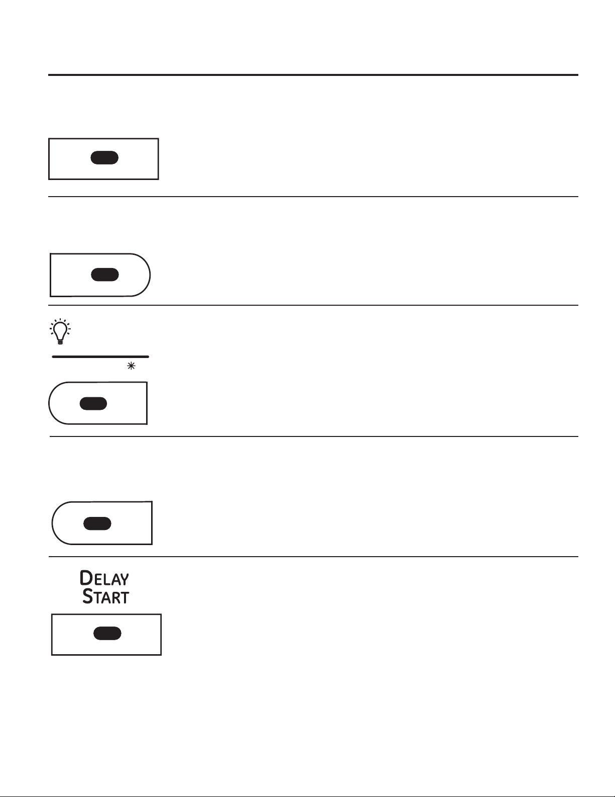
Options de cycle.
REMARQUE:
Certaines caractéristiques peuvent ne pas être offertes sur tous les modèles de sécheuses.
www.electromenagersge.ca
Extend Tumble (Culbutage prolongé)
Réduit les faux plis au maximum en ajoutant environ
60 minutes de culbutage sans chaleur une fois que les
vêtements sont secs.
La lumière au centre du bouton s’allume lorsque
EXTENDED TUMBLE (culbutage prolongé) est activé.
Extend Tumble (Culbutage Prolongé) est
automatiquement sélectionné pour le cycle
SteamRefresh et ne pas pas être dé-sélectionner.
La sécheuse émettra un bip et affichera «
Garments Ready » (Vêtements Prêt) lorsque le cycle
SteamRefresh est terminé. La sécheuse continuera en
Extend Tumble jusqu’à la porte soit ouverte.
Damp Alert (Alerte d’humidité)
Cette option fait sonner la sécheuse quand les
vêtements ont été séchés jusqu’à un certain niveau
d’humidité. Retirez les articles que vous souhaitez
étendre pour sécher. DAMP ALERT (L’ALERTE DU
NIVEAU D’HUMIDITÉ) retentira uniquement quand
cette option est sélectionnée.
Le fait de retirer les vêtements et les étendre quand
ils sont humides peut diminuer le besoin de repasser
certains articles.
La lumière au centre du bouton s’allume lorsque
DAMP ALERT (alerte linge humide) est activé
Drum Light (Lumière du tambour)
Appuyez sur cette touche pour allumer la lumière de
la sécheuse.
Appuyez à nouveau sur cette touche pour éteindre
la lumière.
Ceci contrôle la lumière uniquement quand la porte
est fermée.
REMARQUE : La lumière s’éteindra automatiquement
après une minute lorsque la porte est fermée.
Quand la porte est ouverte, la lumière s’allume
automatiquement.
La lumière au centre du bouton s’allume lorsque
DRUM LIGHT (lumière de tambour) est activée.
REMARQUE: Maintenez le bouton DRUM LIGHT appuyé
pendant 3 secondes pour accéder au menu SETTINGS
(réglages). (Plus de détails page 10).
Delay Start (Mise en marche différée)
Utilisez pour retarder le démarrage de votre sécheuse.
1. Sélectionnez votre cycle de séchage et toutes les
options.
2. Appuyez sur DELAY START (MISE EN MARCHE
DIFFÉRÉE). Vous pouvez changer le délai d’attente
par intervalles de 30 minutes en utilisant les
flèches ou .
3. Appuyez sur la touche START/PAUSE (MISE EN
MARCHE/PAUSE) pour lancer le compte à rebours.
Le compte à rebours sera indiqué sur l’affichage «
ESTIMATED TIME REMAINING » (TEMPS RESTANT
ESTIMÉ).
REMARQUES:
Si la porte est ouverte alors que la sécheuse est
en mode DELAY (MISE EN MARCHE DIFFÉRÉE),
le compte à rebours ne redémarrera pas sauf
si la porte est fermée et que la touche START/
PAUSE (MISE EN MARCHE/PAUSE) est à nouveau
enfoncée.
Vous pouvez retarder le démarrage d’un cycle
de séchage jusqu’à 24 heures.
La lumière au centre du bouton s’allume lorsque
DELAY START (mise en marche différée) est activé.
61
EXTENDED
TUMBLE
DAMP
ALERT
DRUM
LIGHT
SETTINGS
e
DRY
e-Dry
Réduit la consommation totale d’énergie des cycles
spécifiques de la sécheuse en ajustant certains
réglages de température.
REMARQUE: Les durées de cycle changent lorsque
e-DRy est sélectionné.
Ce cycle peut être utilisé avec les tissus DÉLICATS,
SPORT, EASY CARE, les CHARGES NORMALES/
MÉLANGÉES et les COTONS.
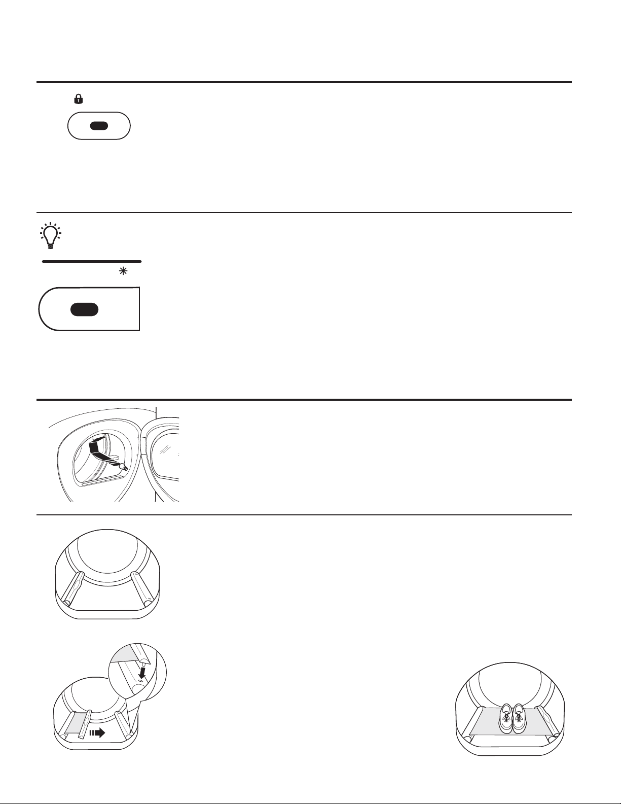
Settings (Réglage)
Dans l’option SETTINGS (RÉGLAGE), vous
pouvez ajuster le volume ou la luminosité de
l’affichage.
VOLUME
Le volume du signal de fin de cycle peut
être réglé sur HIGH (HAUT), MED (MOYEN),
LOW (BAS) ou OFF (ARRÊT).
Le volume de la tonalité des commandes
peut être réglé sur HIGH, MED, LOW ou
OFF.
La luminosité de l’affichage (DISPLAY
BRIGHTNESS) peut être réglée sur HIGH, MED
ou LOW.
Une fois que vous avez effectué votre
sélection, appuyez sur ENTER (ENTRÉE).
REMARQUE: Maintenez le bouton DRUM
LIGHT appuyé pendant 3 secondes pour
accéder au menu SETTINGS (réglages).
62
À propos des caractéristiques de la sécheuse.
« Built-In Rack Dry System »
Un support de séchage pratique peut être utilisé pour sécher des articles comme les
chaussures de tennis. Placez les articles à plat sur le support de séchage et bloquez les
pulls en laine ou les tissus délicats. Séchez à faible chaleur.
Pour installer le « Built-In Rack Dry System »
1. Assurez-vous que le tambour de la sécheuse est orienté de sorte que le système de
support de séchage se trouve sur le côté gauche de la sécheuse.
2. Tirez sur le support de séchage du côté gauche et engagez les “tiges” de la poignée
dans les fentes se trouvant à l’opposé.
3. Placez le vêtement sur le support et fermez la porte.
4. Appuyez sur la touche DRYER RACK (GRILLE DE SÉCHAGE).
5. Sélectionnez le temps désiré.
6. Appuyez sur la touche START/PAUSE (MISE EN MARCHE/
PAUSE).
REMARQUE:
N’utilisez pas ce support de séchage quand d’autres
vêtements sont dans la sécheuse.
Assurez-vous de détacher le support de séchage à la fin
du cycle et rabattez entièrement le support de séchage à
l’intérieur du déflecteur.
Lumière de tambour
Avant de remplacer l’ampoule, assurez-vous de débrancher le cordon d’alimentation de la
sécheuse ou de couper l’alimentation au panneau de distribution électrique en enlevant le
fusible ou en déclenchant le disjoncteur. Accédez au dessus de l’ouverture de la sécheuse
depuis l’intérieur du tambour. Retirez l’ampoule et remplacez-la par une ampoule de
même taille.
Options de cycle.
REMARQUE:
Certaines caractéristiques peuvent ne pas être offertes sur tous les modèles de sécheuses.
Enfoncez les potences
Bouton de verrouillage
Appuyez 3 secondes pour déverrouill
e
LOCK
DRUM
LIGHT
SETTINGS
Lock (Verrouillage)
Vous pouvez verrouiller les commandes pour en éviter
la sélection. Ou vous pouvez verrouiller les commandes
après le démarrage d’un cycle.
Avec cette option sélectionnée, les enfants ne peuvent
plus démarrer la sécheuse accidentellement en
appuyant sur les touches.
Pour verrouiller la sécheuse, appuyez sur la touche
LOCK (VERROUILLAGE). Pour déverrouiller la sécheuse,
appuyez sur la touche LOCK et maintenez-la enfoncée
pendant 3 secondes.
La lumière au centre du bouton de verrouillage
LOCK s’allume lorsque les commandes sont
verrouillées.
Le voyant autour de la touche LOCK s’illuminera quand
les commandes sont verrouillées.
Même si les commandes sont verrouillées, la touche
POWER (ALIMENTATION) est encore active au cas où
vous auriez besoin d’éteindre l’unité.
Appuyez et maintenez appuyé
pendant 3 secondes pour des
options secondaires
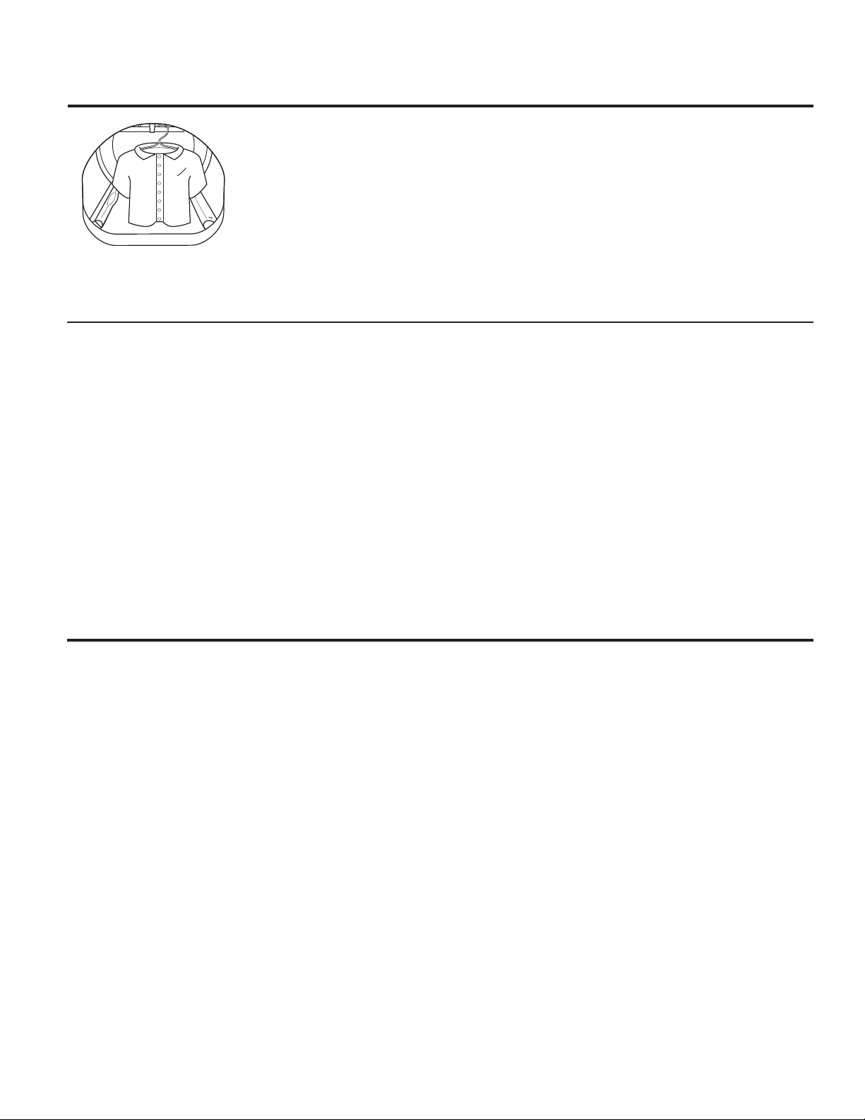
À propos des caractéristiques de la sécheuse.
www.electromenagersge.ca
Utilisation du crochet incorporé
pour accrocher des vêtements
1. Assurez-vous que le tambour de la
sécheuse est orienté de sorte que le
crochet soit situé sur la partie supérieure
centrale de la sécheuse.
2. En utilisant votre doigt, retirez le crochet
de la fente.
3. Accrochez le vêtement sur un cintre,
accrochez ce derniersur le crochet et
fermez la porte.
4. Appuyez sur la touche DRYER RACK
(GRILLE DE SÉCHAGE).
5. Sélectionnez le temps désiré.
6. Appuyez sur la touche START/PAUSE (MISE
EN MARCHE/ PAUSE).
Reverse Tumble
MC
Toutes les sécheuses à chargement frontal Profile sont dotées de la fonction Reverse
Tumble
MC
, une option incorporée au système Duo Dry Plus
MC
. En inversant le sens de rotation
du tambour pendant le cycle de séchage, votre sécheuse mélangera moins votre linge, le
séchera de façon plus homogène et écourtera le séchage. Les charges habituelles telles que
celles composées de draps, de serviettes de bain et de housses sont les premières à profiter
de cette fonctionnalité. Lorsque la sécheuse inverse le culbutage, une courte pause s’amorce
et le bruit émis par la machine change. Ne vous inquiétez pas, c’est normal. Tous les cycles de
la sécheuse utilisent cette fonctionnalité, sauf lorsque l’option de séchage à l’aide du support
ou de la grille de séchage est sélectionnée, auquel cas le tambour ne tourne pas.
63
Utilisation de la sécheuse.
Suivez toujours l’étiquette du fabricant de tissus pour laver.
Conseils pour le tri et le chargement
En règle générale, lorsque les vêtements sont
correctement triés pour le lavage, ils le sont
aussi pour le séchage. Essayez aussi de trier les
articles en fonction de leur taille. Par exemple,
ne séchez pas un drap avec des chaussettes ou
d’autres petits articles.
N’ajoutez pas votre feuille d’assouplissant textile
lorsque la brassée a commencé à chauffer,
car elle risque de provoquer des taches
d’assouplissant. Les feuilles d’assouplissant
de tissus Bounce
MD
pour sécheuses ont été
approuvées pour cette sécheuse si elles sont
utilisées conformément aux instructions du
fabricant.
Voir ci-dessous pour les consignes de nettoyage
du filtre à charpie.
Ne surchargez pas. Ceci consomme inutilement
de l’énergie et cause des faux plis.
Ne séchez pas les articles suivants: Articles
en fibre de verre, lainages, articles recouverts
de caoutchouc, plastiques, articles dotés d’une
garniture en plastique, articles remplis de
mousse de caoutchouc.
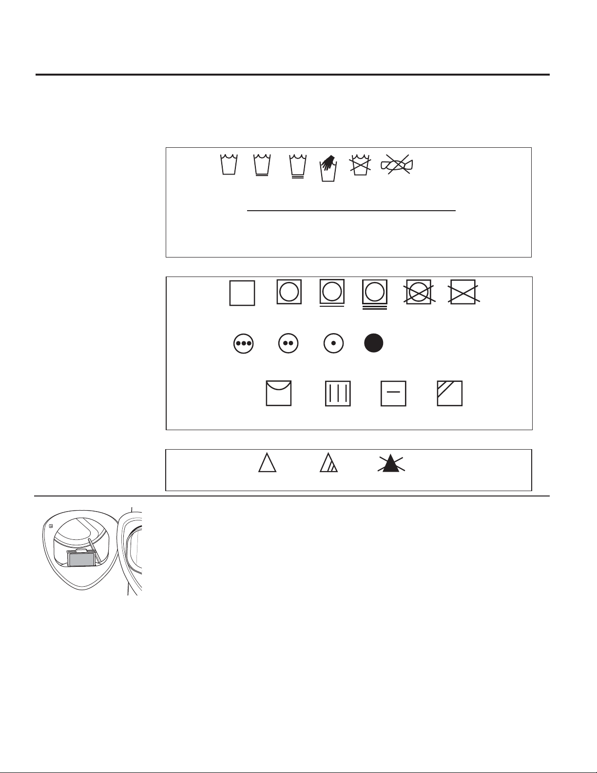
64
Utilisation de la sécheuse.
Entretien et nettoyage de la sécheuse
Intérieur de la sécheuse et conduit: L’intérieur
de la machine et du conduit d’évacuation doit
être nettoyé une fois par an par du personnel de
service qualifié.
Extérieur: Essuyez les produits de lessive
renversés, et enlevez la poussière avec un linge
humide. Le fini et le panneau de contrôle de la
sécheuse peuvent être endommagés par certains
produits de traitement préliminaire et détachants.
Appliquez ces produits loin de la sécheuse. Vous
pouvez ensuite laver et faire sécher les vêtements
normalement. Les dommages causés à votre
sécheuse par ces produits ne sont pas couverts
par votre garantie.
Ne touchez pas la surface ou l’écran avec des
objets pointus.
Filtre à charpie: Nettoyez le filtre à charpie avant
chaque utilisation. Sortez-le en le tirant vers le
haut. Faites passer vos doigts sur le filtre. Un
amas cireux peut se former sur le filtre à charpie
à cause de l’utilisation des feuilles d’assouplissant
textile. Pour éliminer cet amas, lavez le filtre à l’eau
chaude savonneuse. Séchez-le soigneusement et
replacez-le. N’utilisez pas la sécheuse sans le filtre
à charpie en place.
Aspirez la charpie de la zone du filtre à charpie
si vous remarquez une modification des
performances de la sécheuse.
Acier inoxydable: Pour nettoyer les surfaces en
acier inoxydable, utilisez un chiffon humidifié avec
un nettoyant doux et non abrasif, adapté aux
surfaces en acier inoxydable. Éliminez les résidus
de nettoyant, puis séchez avec un chiffon propre.
L’acier inoxydable utilisé pour fabriquer le tambour
de séchage fournit la plus haute fiabilité disponible
dans une sécheuse GE. Si le tambour de séchage est
rayé ou ébréché pendant une utilisation normale,
le tambour ne rouillera pas ou ne se corrodera
pas. Ces défauts de surface n’affecteront pas le
fonctionnement ou la durabilité du tambour.
Évent d’evacuation: Vérifiez avec un miroir que
les volets à l’intérieur de l’évent se déplacent
librement lors du fonctionnement. Assurez-vous
qu’aucun animal (oiseaux, insectes, etc.) ne s’est
introduit dans le conduit ou l’évent.
Tumble
dry
Dry
Normal
Permanent Press/
wrinkle resistant
Gentle/
delicate
Do not tumble dry
Do not dry
(used with
do not wash)
Heat
setting
High
Medium
Low
No heat/air
Special
instructions
Line dry/
hang to dry
Drip dry
Dry flat
In the shade
ÉTIQUETTES DE SÉCHAGE
ETIQUETTES DE LAVAGE
Étiquettes d’entretien de tissu
Ci-dessous figurent les « symboles » des étiquettes d’entretien de tissu qui concernent le linge à
sécher.
Séchage
Séchage
par
culbutage
Réglage
de chaleur
Instructions
spéciales
Normal
Sans repassage/
infroissables
Doux/délicat
Ne pas sécher
par culbutage
Haut
Moyen Bas Pas de chaleur/
aération
Sécher en suspendant
après essorage
Sécher par
égouttage
Sécher à plat
Sécher à l’ombre
Ne pas sécher
(utilisé avec
ne pas laver)
Machine
wash
cycle
Normal
Permanent Press/
wrinkle resistant
Gentle/
delicate
Hand wash
Do not wash Do not wring
Front load
target water
temperature
Target Automatic
Category Water Temperature Temperature Control
Tap Cold Inlet Water Temperature Not used
Cold 27°C/80°F Used
Warm 40°C/105°F Used
Hot 50°C/120°F Used
Sanitize 70°C/160°F Used
AGENT DE BLANCHIMENT
Bleach
symbols
Any bleach
(when needed)
Only non-chlorine bleach
(when needed)
Do not bleach
Symboles pour
agent de
blanchiment
Tout type d’agent de
blanchiment (si nécessaire)
Agent de blanchiment
non chloré
Ne pas utiliser d’agent
de blanchiment
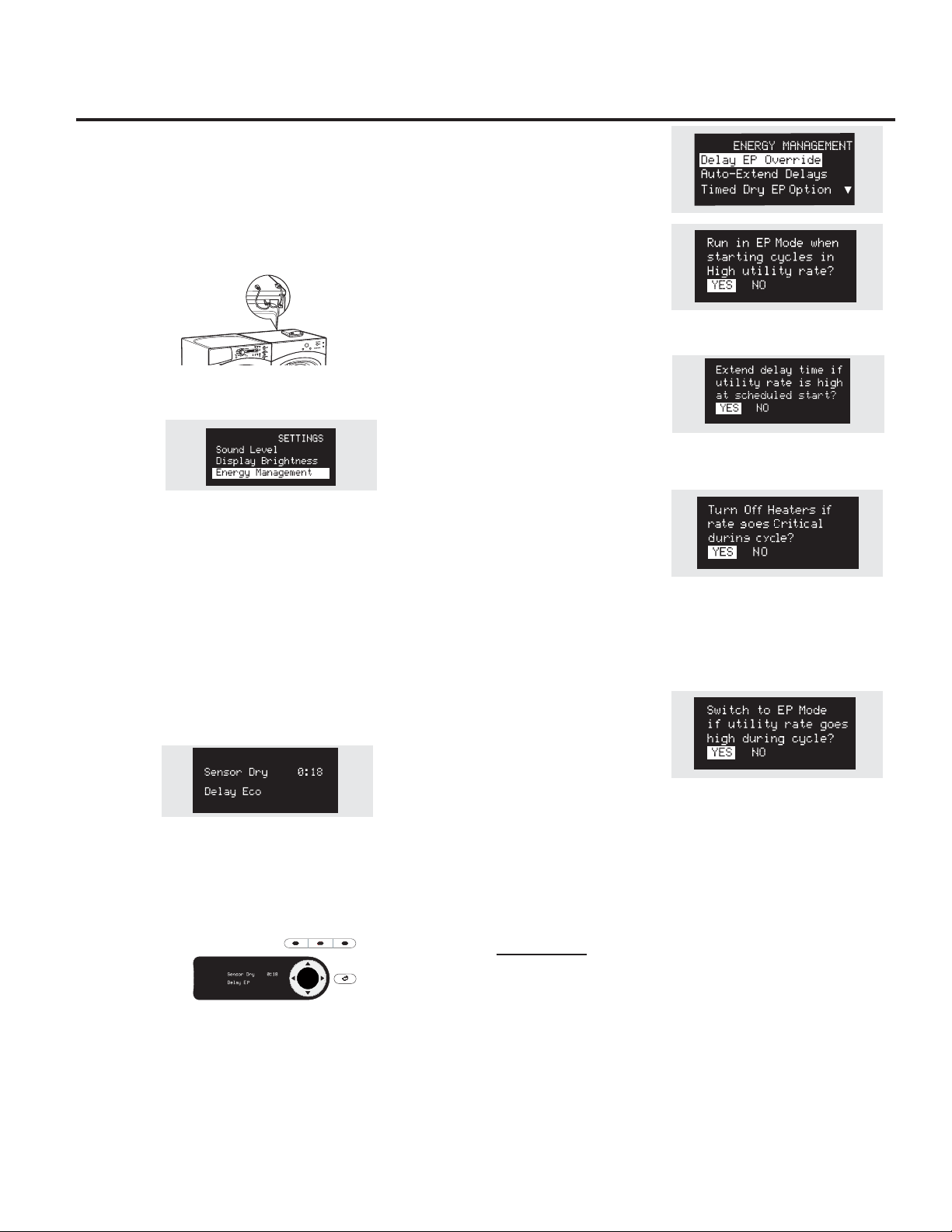
Les modèles PFDS450, PFDS455, PFDN440, PFDN445 sont compatibles
avec le module d’appareil intelligent (SAM) GE qui peut être acheté
séparément. Contactez la compagnie d’électricité locale ou rendez-vous
à www.GEAppliances.com/smart-appliances pour voir si votre zone
utilise la technologie de réponse à la demande.
Installation
L’endroit préféré pour l’installation de module est sur la sécheuse de
vêtements.
Les instructions fournies avec le module incluent les détails sur la façon
de brancher les câbles au module.
Attendez 5
minutes, puis appuyez sur le bouton Settings (Réglages). Faites défiler
le menu jusqu’à l’affichage de « Energy management » (gestion de la
consommation électrique), comme indiqué ci-dessous.
Cet écran signifie que le module est correctement fixé et que vous
pouvez commencer à utiliser l’appareil intelligent en suivant les
instructions ci-dessous.
Si l’écran de gestion d’énergie n’est pas disponible, reportez-vous au
guide de dépannage du module SAM.
Guide Rapide
4 niveaux énergétiques sont disponibles : Critical (critique), High (élevé),
Medium (moyen) et Low (faible). Aux niveaux Medium (moyen) et
Low (faible), l’appareil fonctionne normalement. Les étapes suivantes
indiquent la façon dont l’unité réagit lors de la mise en marche aux
niveaux énergétiques Critical (critique) et High (élevé).
Option 1 (Delay EP – Départ Différé EP)
Au moment de la mise en marche lors des niveaux Critical (critique)
et High (élevé), l’appareil retardera la mise en marche en attendant
le retour à un niveau Medium (moyen) ou Low (faible). Appuyez sur le
bouton START/PAUSE (Marche/pause).
Option 2 (Override Delay EP – Annuler Départ Différé EP)
Pour mettre en marche unité lorsqu’elle affiche Delay Eco (Départ
Différé ÉP), appuyez sur le bouton DELAY START (Mise en marche
différée) pour annuler le départ différé. Puis, appuyez sur START/PAUSE
(Marche/pause) pour lancer un cycle de lavage. Pendant une période
de tarif critique, le mode de réponse critique** sera aussi activé pour
maximiser les économies d’énergie. EP sera affiché.
Option 3 (Annuler « e » DRy)
Après annulation de la fonction de délai, appuyer sur le bouton « e »DRy
désactive le réglage « e »DRy. Appuyer sur la touche START/PAUSE commence
le cycle sélectionné.
Pendant une période de tarif critique, le mode de réponse critique** sera activé
pour maximiser les économies d’énergie. EP sera affiché.
**Remarque : Le mode de réponse critique peut être désactivé à tout moment
en appuyant sur le bouton « e »Dry et en le maintenant appuyé pendant 3
secondes. EP ne sera plus affiché.
Menu de Réglage
Appuyez sur SETTINGS (réglages)
puis sélectionnez Energy
Management (Gestion de la
Consommation Électrique).
Delay EP Override (Annulation
Départ Différé EP)
Si vous lancez un cycle lors des tarifs
Critique (critique) ou High (élevé),
grâce à cette option, l’appareil
fonctionne automatiquement en
Cycle Eco. Ce réglage vous permet
d’utiliser moins d’énergie qu’avec un cycle normal. Le réglage par défaut est YES (Oui).
Auto-Extend Delays
(Prolongation automatique du
délai)
Si un départ différé est sélectionné,
cette option permet de prolonger
le délai si le tarif au moment de
la mise en marche est Critical (critique) ou High (Élevé). Le réglage par défaut
prolonge automatiquement ces cycles.
Option Critical Rate (tarif
critique)
Cette option permet à l’appareil
intelligent de répondre à
l’information de tarif critique en
engageant automatiquement le
mode de réponse critique. Le
mode Critical Response (réponse critique) est conçu pour maximiser les
économies d’énergie lorsqu’un cycle est exécuté pendant une période de tarif
critique. Le réglage par défaut est YES (oui). Régler cette option sur NO (non)
désactive le mode Critical Response (Réponse critique) d’appareil intelligent.
Séchage Minuté Option EP
Si l’appareil fonctionne dans
le mode Timed Dry (Séchage
Minuté) et le tarif devient
Critical (critique) ou High (élevé),
l’appareil préservera de l’énergie
en diminuant la chaleur si YES
(Oui) (défaut) est sélectionné. Si
NO est sélectionné, l’appareil fonctionnera normalement.
NOTE: Quand YES (Oui) ( défaut) est sélectionné, votre charge peut être
humide à la fin du cycle.
Pour que les fonctionnalités d’appareil intelligent soient opérationnelles, un
équipement supplémentaire doit être installé à l’interface avec vos services
publics. Cet équipement peut être vendu séparément et/ou est disponible auprès
de vos services publics dans le cadre de ce programme d’essai pilote. Vérifiez
auprès de vos services publics si le programme d’essai pilote est disponible dans
votre zone ainsi que pour obtenir de plus amples informations.
VEUILLEZ NOTER:
À la fin du programme d’essai pilote ou si vous déménagez
dans une zone où le programme n’est pas disponible, les fonctions de réponse
à la demande ne pourront être activées ni utilisées sur votre appareil. L’appareil
fonctionnera normalement après que l’équipement de réponse à la demande ait
été désactivé ou déconnecté.
APPAREIL INTELLIGENT. (sur certains modèles) www.electromenagersge.ca
65
ENTER
DELAY
STAR T
e
DRY
DRYER
RACK
BACKBACK
AVANT DE COMMENCER
Lisez attentivement ces instructions dans leur
intégralité.
•
IMPORTANT – Gardez ces instructions
pour l’usage de l’ inspecteur électrique local.
•
IMPORTANT – Observez toutes les
réglementations et ordonnances en vigueur.
• Installez la sécheuse conformément aux
instructions du fabricant et aux réglementations
locales..
• Remarque pour l’installateur – Assurez-vous de
laisser ces instructions au client.
• Remarque pour le consommateur - Gardez ces
instructions à titre de référence ultérieure.
• L’installation de la sécheuse doit être effectuée
par un installateur qualifié.
• Cette sécheuse doit être mise à l’évent à l’extérieur.
• Retirez la porte de la vieille sécheuse avant de la
mettre au rebut ou hors service.
• Les renseignements d’entretien et le schéma
de câblage se trouvent dans la console de
commande.
• Ne laissez pas les enfants monter sur l’appareil
ou entrer dans celui-ci. Une surveillance étroite
des enfants doit être exercée lorsque l’appareil
est utilisé à leur proximité.
• La responsabilité d’installer correctement
l’appareil relève de l’installateur.
• Toute défaillance de l’appareil suite à une
installation incorrecte n’est pas couverte par la
garantie.
• Installez la sécheuse là où la température est
supérieure à 10,00” (50 F) pour assurer le bon
fonctionnement du système de commande de la
sécheuse.
• Retirez et jetez les conduits en feuille métallique
ou en plastique existants et remplacez-les par un
conduit homologué UL.
Instructions
Sécheuse
d’installation
66
Si vous avez des questions, appelez 800.GE.CARES ou visitez notre site web: www.GEAppliances.com
Au Canada, appelez le 1.800.561.3344 ou visitez www.electromenagersge.ca
POUR VOTRE SÉCURITÉ:
AVERTISSEMENT – Risque
d’incendie
• Pour réduire le risque de blessure grave, voire de
mort, suivez toutes les instructions d’installation.
•
L’installation de la sécheuse doit être effectuée par
un installateur qualifié.
•
Installez la sécheuse conformément aux instructions
du fabricant et aux réglementations locales.
•
Cette sécheuse doit être mise à l’évent à l’extérieur.
•
N’utilisez que des conduits métalliques rigides de
10 cm de diamètre à l’intérieur du placard de la
sécheuse et utilisez uniquement du conduit de
transition homologué UL entre la sécheuse et le
conduit de la maison.
•
N’installez PAS de sécheuse avec des conduits
en plastique flexible. Si un conduit métallique
flexible (semi-rigide ou du type feuille métallique)
est installé, il doit être homologué UL et installé
conformément aux instructions figurant dans
“Connecter la sécheuse à l’évent de la maison”
page 26 de ce manuel. Les conduits flexibles ont
tendance à s’affaisser, à être facilement écrasés
et à piéger la charpie. Ces conditions bouchent le
débit d’air de la sécheuse et augmentent le risque
d’incendie.
•
N’installez et ne remisez pas cet appareil dans un
lieu où il peut être exposé à l’eau ou aux intempéries.
•
Gardez ces instructions. (Installateurs: Assurez-vous
de laisser ces instructions au client.
POUR LES MODÈLES À GAZ
UNIQUEMENT:
REMARQUE: L’installation et la maintenance de cette
sécheuse doivent être réalisées par un installateur qualifié,
une agence de service ou le fournisseur de gaz.
Dans le Commonwealth du Massachusetts :
•
Ce produit doit être installé par un plombier ou un
monteur d’installations au gaz licencié.
•
Si vous utilisez des robinets d’arrêt du gaz à bille, ils
doivent avoir une poignée en T.
•
Si vous utilisez un raccord de gaz souple, il ne doit pas
dépasser 1 m (3 pieds).
PFDS450 / PFDS455 /PFDN440 / PFDN445 /
PFMS450 / PFMS455 / PFMN440 / PFMN445
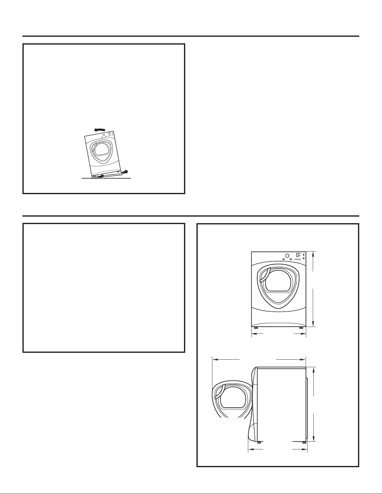
Instructions d’installation
67
DÉBALLAGE DE VOTRE SÉCHEUSE
Inclinez la sécheuse latéralement et enlevez les
coussinets d’expédition en mousse en les poussant
sur les côtés et en les détachant des pattes de la
sécheuse. Assurez-vous d’enlevez toutes les pièces
en mousse autour des pattes.
Enlevez le sac contenant la grille de séchage,la
documentation et le câble série.
DIMENSIONS DE LA SÉCHEUSE
51″
(129.5 cm)
39.1″
(993 cm)
32.34″
(847 cm)
27″
(68.6 cm)
39.1″
(993 cm)
68,6 cm
(27 po)
100,3 cm
(39,5 po)
85,1 cm
(33,5 po)
100,3 cm
(39,5 po)
Vue
latérale
Vue avant
EMPLACEMENT DE VOTRE SÉCHEUSE
DÉGAGEMENTS MINIMUMS AUTRES
QUE POUR UNE INSTALLATION
ENCASTRÉE
Les dégagements minimums rapport aux surfaces
combustibles et pour les orifices d’aération sont les
suivants :
•
un dégagement de 0 mm (0 po) des deux côtés
• 25 mm (1 po) à l’avant
• 75 mm (3 po) à l’arrière
Il est nécessaire de prévoir des dégagements
appropriés pour le fonctionnement et l’entretien de
la machine.
134,6 cm
(53 po)
68
Instructions d’installation
EXIGENCES RELATIVES À UNE
INSTALLATION ENCASTRÉE
• Votre sécheuse est homologuée pour une
installation dans une alcôve ou dans un placard,
comme l’indique l’étiquette figurant au dos de la
sécheuse.
•
L’air de la sécheuse DOIT être évacué vers
l’extérieur. Consultez la section ÉVACUATION DE
LA SÉCHEUSE.
•
L’espace minimum entre la sécheuse et les murs
adjacents ou d’autres surfaces est le suivant:
0 mm (0 po) des deux côtés
75 mm (3 po) avant et arrière
•
La distance verticale minimum du sol aux étagères
suspendues, armoires, plafonds, etc. de 132 cm (52
po).
•
Les portes du placard doivent être perforées ou
ventilées et doivent disposer d’un espace ouvert
réparti de façon homogène d’au moins 1,5 m
2
(60 po carrés) de superficie. Si une laveuse et
une sécheuse ont été installées dans le placard,
les portes doivent disposer d’un d’espace ouvert
réparti de façon homogène d’au moins 3 m
2
(120
po carrés).
•
L’air du placard doit être évacué vers l’extérieur
afin d’éviter la formation de poches de gaz si le
tuyau d’alimentation de gaz transporte du gaz.
•
Aucun autre appareil à combustible ne doit être
installé dans le placard dans lequel se trouve la
sécheuse (modèles à gaz uniquement).
REMARQUE: SI LE TUYAU D’ÉVACUATION EST SITUÉ À
L’ARRIÈRE DE LA SÉCHEUSE, L’ESPACE MINIMUM PAR
RAPPORT AU MUR EST DE 14 CM (5,5 PO).
INSTALLATION DANS UNE SALLE
DE BAIN OU UNE CHAMBRE
• L’air de la sécheuse DOIT être évacué vers
l’extérieur. Consultez la section ÉVACUATION DE
LA SÉCHEUSE.
•
L’installation doit être conforme aux normes
locales ou, en l’absence de normes locales, avec
le CODE NATIONAL DE L’ÉLECTRICITÉ, ANSI/NFPA
N° 70 (pour les sécheuses électriques) ou le CODE
NATIONAL DU GAZ, ANSI Z223 (pour les sécheuses
à gaz).
INSTALLATION DANS UNE MAISON
MOBILE OU PRÉFABRIQUÉE
• L’installation doit être conforme à la NORME
DE SÉCURITÉ POUR LA CONSTRUCTION DE
MAISONS FABRIQUÉES, TITRE 24, PARTIE 32–80
ou, si la norme n’est pas applicable, à la NORME
NATIONALE AMÉRICAINE POUR LES MAISONS
MOBILES N° 501B.
•
L’air de la sécheuse DOIT être évacué vers
l’extérieur avec les raccordements correctement
fixés à la structure de la maison mobile. (Voyez
ÉVACUATION DE LA SÉCHEUSE.)
•
La ventilation NE DOIT PAS déboucher sous une
maison mobile ou fabriquée.
•
Le matériau du tuyau de ventilation DOIT ÊTRE LE
MÉTAL.
•
POUR LES MODÈLES À GAZ UNIQUEMENT:
L’ensemble 14-D346-33 DOIT être utilisé pour
raccorder la sécheuse à la structure.
•
POUR LES MODÈLES À GAZ UNIQUEMENT:
La ventilation NE DOIT PAS être raccordée à tout
autre tuyau, évent ou cheminée.
•
N’utilisez pas de vis à tôle ni d’autres dispositifs
de serrage qui dépassent à l’intérieur de l’évent
d’évacuation.
•
Prévoyez une ouverture dotée d’une zone ouverte
de 63 cm
2
(25 pouces carrés) pour l’infiltration
d’air extérieur dans la pièce de la sécheuse.
INSTALLATION DANS UN GARAGE (SI
PERMIS PAR DES CODES LOCAUX)
• Les sécheuses installées dans des garages
doivent être élevées à 46 cm au-dessus du sol.
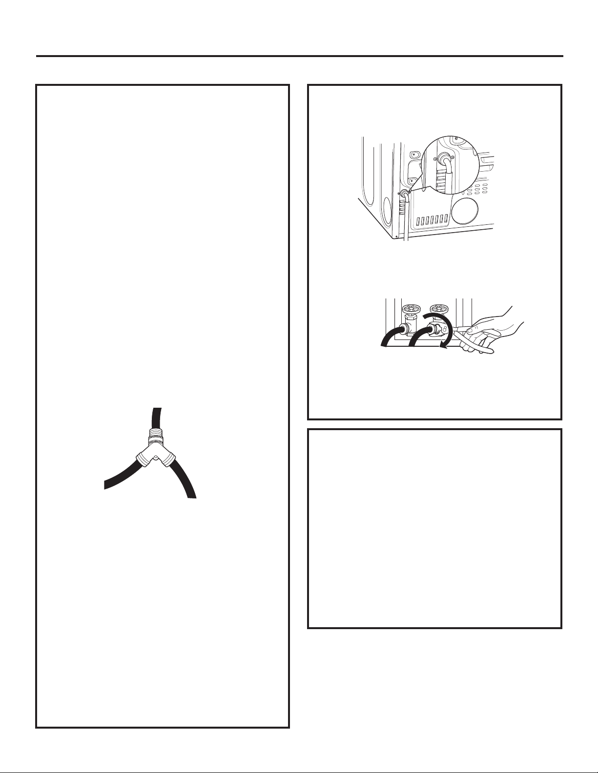
69
Instructions d’installation
BRANCHEMENT DES BOYAUX D’ARRIVÉE
BRANCHEMENT DES BOYAUX D’ARRIVÉE
Pour produire de la vapeur, la sécheuse doit être
branchée à une alimentation d’eau froide. Puisque la
laveuse doit aussi être branchée à une alimentation
d’eau froide, un connecteur en « Y » est inséré, afin
de permettre aux boyaux d’arrivée d’être brancher
au même moment.
REMARQUE: Utilisez les boyaux d’arrivée fournis, ne
jamais utiliser de vieux boyaux.
1. Fermez le robinet d’eau froide. Débranchez le
boyau d’arrivée du connecteur du robinet de
remplissage (froid).
2. Assurez-vous que la rondelle plate en caoutchouc
est en place et vissez le raccord femelle du boyau
court sur le connecteur du robinet de remplissage
de la laveuse. Resserrez à la main jusqu’à ce qu’il
soit bien serré. Resserrez à la main jusqu’à ce qu’il
soit bien serré.
3. Raccordez l’extrémité femelle du connecteur en
« Y » au raccord mâle du boyau court. Assurez-
vous que la rondelle plate en caoutchouc est en
place. Resserrez à la main jusqu’à ce qu’il soit
bien vissé.
4. Insérez la grille de filtre dans le raccord du boyau
d’arrivée de la laveuse. Si une rondelle plate en
caoutchouc est déjà en place, retirez-la avant
d’installer la grille de filtre. Raccordez ce raccord
à une extrémité mâle du connecteur en « Y ».
Resserrez à la main jusqu’à ce qu’il soit bien serré.
5. Assurez-vous que la rondelle plate en caoutchouc
est en place et raccordez le boyau d’arrivée long
de la sécheuse à l’autre extrémité mâle du
connecteur en « Y ». Resserrez à la main jusqu’à
ce qu’il soit bien serré.
6. Assurez-vous que la rondelle plate en caoutchouc
est en place et raccordez l’autre extrémité
du boyau d’arrivée long de la sécheuse au
connecteur du robinet de remplissage dans le
bas du panneau arrière de la sécheuse. Resserrez
à la main jusqu’à ce qu’il soit bien serré.
BRANCHEMENT DES BOYAUX D’ARRIVÉE
(suite)
7. En utilisant des pinces, resserrez toutes les
connexions avec un tour au deux-tiers.
REMARQUE: Ne pas trop serrer. Vous pourriez
endommager les connexions.
8. Ouvrez le robinet d’eau.
9. Vérifiez l’absence de fuites autour du connecteur
en « Y », du robinet et des raccords de boyau.
EXIGENCES DE L’ALIMENTATION D’EAU
Les robinets d’eau chaude et d’eau froide DOIVENT
être installés à une distance d’au moins 42 po (107
cm) du boyau d’eau de la laveuse. Les robinets
DOIVENT être de type boyau de jardin de 3/4 po
(1,9 cm) pour que les boyaux d’arrivée puissent être
branchés. La pression de l’eau DOIT être entre 10 et
120 livres par pouce carré. Votre département d’eau
peut vous laisser savoir ce qu’est votre pression
d’eau.
REMARQUE: Un adoucisseur d’eau est recommandé
pour réduire l’accumulation de déport à l’intérieur
du générateur de vapeur si l’alimentation d’eau de
la maison est très dure.
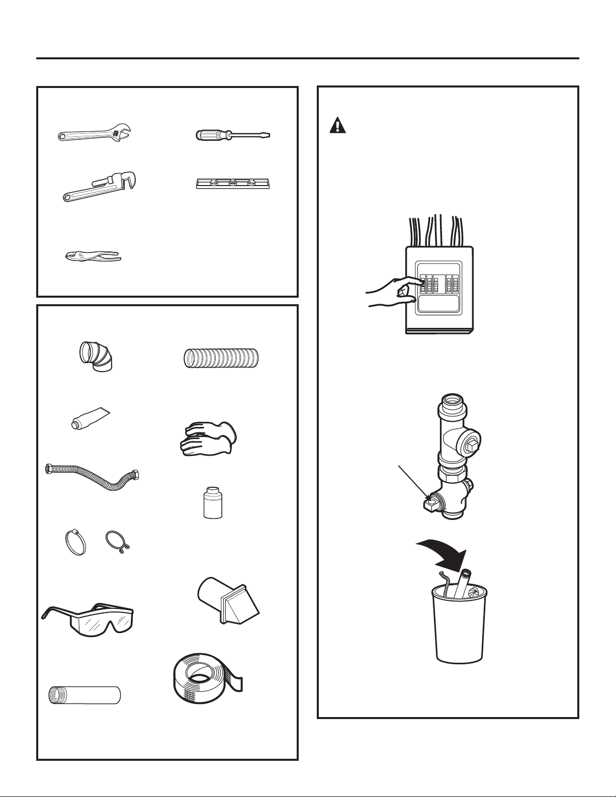
70
Instructions d’installation
RACCORDEMENT D’UNE SÉCHEUSE À GAZ (non applicable aux sécheuses électriques)
POUR VOTRE SÉCURITÉ :
AVERTISSEMENT
Avant de démarrer l’installation, déclenchez le
disjoncteur ou enlevez le fusible de la sécheuse au
panneau de distribution électrique. Assurez-vous
que le cordon d’alimentation de la sécheuse est
débranché de la prise murale.
Fermez la vanne d’arrêt du gaz de la sécheuse de la
conduite d’alimentation.
Démontez et jetez l’ancien connecteur de gaz
flexible et l’ancien conduit.
Vanne
d’arrêt
MATÉRIEL NÉCESSAIRE
Coude métallique 4
po de diamètre
Mastic pour joints de
tuyaux
Tuyau de
raccordement souple
Colliers de conduit (2)
ou brides à ressort
(2)
Lunettes de
protection
Tuyau métallique
4 po de diamètre
(recommandé)
Tuyau métallique
souple 4 po de
diamètre (si
nécessaire)
Gants
Solution savonneuse
pour la détection de
fuites
Évent d’évacuation
Ruban adhésif
Clés à molette (2) 10 po
Clé à tuyau 8 po
Pince à joint coulissant
Tournevis à tête plate
Niveau
OUTILS NÉCESSAIRES
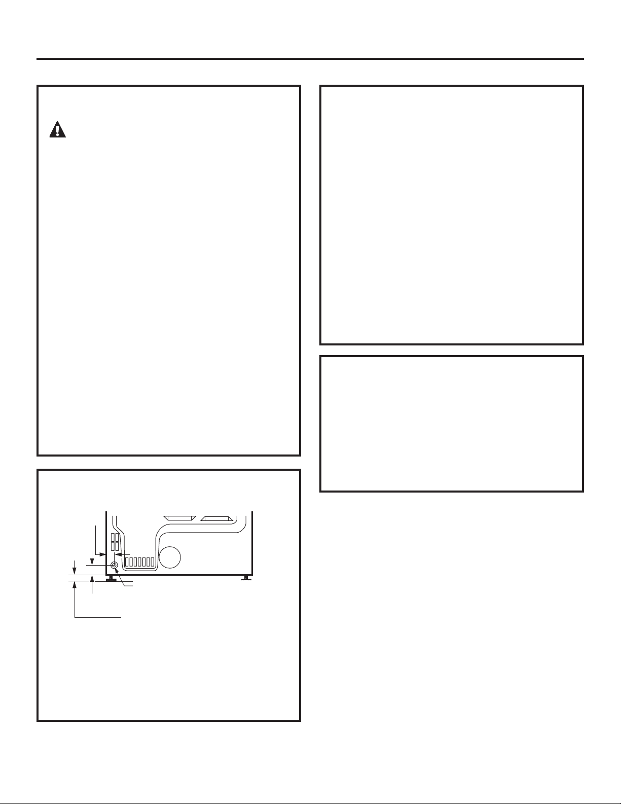
71
Instructions d’installation
EXIGENCES RELATIVES AU GAZ
AVERTISSEMENT
• L’installation doit être conforme aux normes et
aux réglementations locales, ou sinon au CODE
NATIONAL DU GAZ, ANSI Z223. 1/NFPA 54, ou le
Code canadien d’installation du gaz naturel et du
propane CSA B149.1.
•
Cette sécheuse à gaz est équipée d’un ensemble
brûleur et vanne à utiliser uniquement avec du
gaz naturel. Grâce à l’ensemble de conversion
14-A048, votre agence de service locale
peut transformer cette sécheuse pour une
utilisation avec du gaz propane (LP). TOUTES LES
TRANSFORMATIONS DOIVENT ÊTRE RÉALISÉES
PAR DU PERSONNEL FORMÉ ET QUALIFIÉ, EN
CONFORMITÉ AVEC LES EXIGENCES DES NORMES
ET DES RÉGLEMENTATIONS LOCALES.
•
La sécheuse doit être débranchée du système
d’alimentation en gaz pendant tout essai de
pression de cet système, avec une pression
d’essai supérieure à 0,5 lb/po
2
(3,4 KPa).
•
La sécheuse doit être isolée du système
d’alimentation en gaz en fermant la vanne
d’arrêt, pendant tout essai de pression des
conduites de gaz avec une pression d’essai égale
ou supérieure à 0,5 lb/po
2
(3,4 KPa).
ALIMENTATION EN GAZ
• Un robinet de raccordement à filetage National
Pipe Taper 3,2 mm (1/8 po), accessible pour
le raccordement d’un manomètre, doit être
installé immédiatement en amont du raccord
d’alimentation en gaz de la sécheuse. Contactez
votre service de gaz local si vous avez des
questions sur l’installation d’un robinet de
raccordement.
•
La conduite d’alimentation doit être composée
d’un tube rigide de 12,7 mm (1/2 po) et équipée
d’une vanne d’arrêt à moins de 1,8 m (6 pieds)
de la sécheuse et dans la même pièce.
•
Utilisez un mastic d’étanchéité approprié au gaz
naturel ou au gaz de petrole liquéfié ou utilisez
du ruban Teflon
®
.
•
Raccordez le tuyau de raccordement métallique
souple à la sécheuse et à l’alimentation en gaz.
DANS LE COMMONWEALTH DU
MASSACHUSETTS
• Ce produit doit être installé par un plombier ou
un monteur d’installations au gaz licencié.
•
Si vous utilisez des robinets d’arrêt du gaz à bille,
ils doivent avoir une poignée en T.
•
Si vous utilisez un raccord de gaz souple, il ne
doit pas dépasser 1 m (3 pieds).
RACCORDEMENT DE L’ALIMENTATION
EN GAZ DE LA SÉCHEUSE
ALIMENTATION EN GAZ À FILETAGE MÂLE NPT 3/8 po
REMARQUE: Ajoutez à la dimension
verticale la distance entre le fond
de la carrosserie et le sol.
6,7 cm (2
5
ø8 po)
5,1 cm (2 po)
Vous devez utiliser un connecteur flexible en
métal certifié par ANSI Z21.24/CSA 6.10. La
longueur du connecteur ne doit pas excéder 3
pieds.
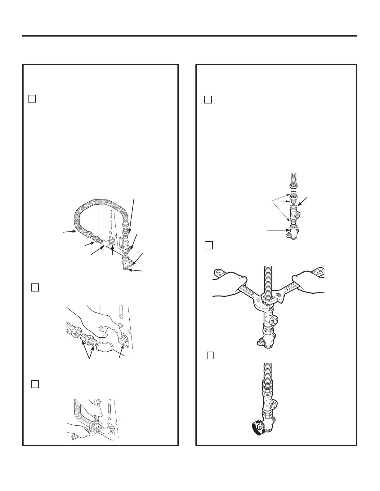
Installez un obturateur 1/8 po NPT sur la vanne
d’arrêt de la ligne de gaz de la sécheuse pour
vérifier la pression d’entrée du gaz.
Installez un raccord adaptateur à l’obturateur.
REMARQUE: Appliquez un mastic d’étanchéité
ou du ruban Teflon® sur les filetages de
l’adaptateur et de l’obturateur.
Instructions d’installation
Fixez le tuyau de raccordement métallique
souple à l’adaptateur.
B
Serrez le raccord du tuyau de raccordement
souple à l’aide de deux clés à molette.
C
D
Serrez tous les raccords à l’aide des deux
clés à molette. Ne serrez pas trop fort.
E
RACCORDEMENT DE LA SÉCHEUSE
À L’ALIMENTATION EN GAZ (suite)
Appliquez un mastic
d’étanchéité ou du
ruban Teflon
MD
sur tous
les filetages mâles.
Ouvrez la vanne d’arrêt de gaz.
F
Vanne d’arrêt
Obturateur
RACCORDEMENT DE LA SÉCHEUSE À
L’ALIMENTATION EN GAZ
Installez un coude femelle 3/8 po NPT à
l’extrémité du raccord d’entrée de gaz de la
sécheuse.
Installez un raccord adaptateur 3/8 po sur le
coude femelle.
IMPORTANT: Utilisez une clé à tuyau pour
tenir fermement l’extrémité du raccord
d’entrée de gaz de la sécheuse pour éviter de
l’endommager.
REMARQUE: Appliquez un mastic d’étanchéité
ou du ruban Teflon® sur les filetages de
l’adaptateur et du raccord d’entrée de gaz de
la sécheuse.
Coude
A
Adaptateur
Matériel non fourni
Adaptateur
Obturateur
de 1/8 po
NPT pour
vérification de
la pression à
l’entrée de gaz
Vanne
d’arrêt
Tuyau d’au
moins 1/2
po
3/8 po NPT
Tuyau de
raccordement
souple
métallique neuf
Appliquez du mastic sur l’adaptateur
et l’entrée de gaz de la sécheuse.
72
RACCORDEMENT D’UNE SÉCHEUSE À GAZ (suite)
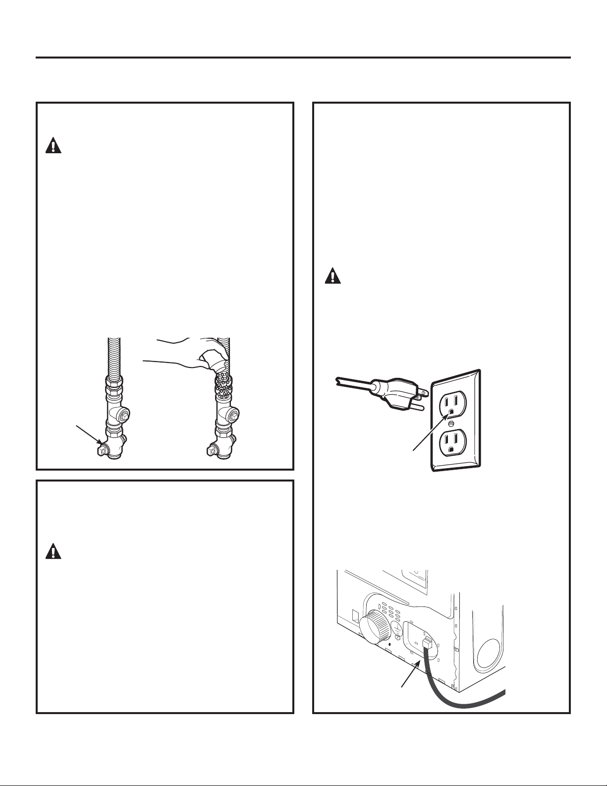
Instructions d’installation
73
DÉTECTION DES FUITES
AVERTISSEMENT – N’utilisez
jamais une flamme nue pour vérifier la présence
de fuites de gaz.
Contrôlez la présence de fuites sur tous les
raccordements avec une solution savonneuse ou
similaire.
Appliquez une solution savonneuse. La solution
de détection des fuites ne doit pas contenir
d’ammoniaque, ce qui pourrait endommager les
raccords en laiton.
Si des fuites sont détectées, fermez la vanne,
resserrez le raccord en cause et répétez la procédure
de détection de fuites.
Ouvrez la
vanne de gaz
EXIGENCES RELATIVES À L’ÉLECTRICITÉ
POUR LES SÉCHEUSES À GAZ
Cette machine doit être alimentée avec du
courant de 120 V, 60 Hz, et raccordée à un circuit
domestique correctement mis à la terre, protégé
par un disjoncteur de 15 ou 20 ampères ou un
fusible temporisé.
Si l’alimentation électrique fournie n’est pas conforme
aux exigences ci-dessus, il est recommandé de faire
installer une prise homologuée par un électricien
qualifié.
AVERTISSEMENT – Cette
sécheuse est équipée d’une fiche à trois broches
(mise à la terre) pour votre protection contre le
risque de choc électrique et elle doit être branchée
directement dans un prise à trois broches
correctement mise à la terre. Ne coupez pas ou
n’enlevez pas la broche de terre de cette fiche.
Assurez-vous au
préalable qu’une mise
à la terre existe bien
et qu’elle fonctionne
correctement.
Si les normes locales le permettent, un fil de terre
externe (non fourni) conforme aux normes locales
peut être ajouté en le fixant à la vis verte de mise
à la terre, située à l’arrière de la sécheuse, pour
établir une mise à la terre alternative.
Vérifiez si la mise à la terre est adéquate avant
utilisation.
Vis de mise
à la terre
INFORMATIONS DE BRANCHEMENT
ÉLECTRIQUE POUR LES SÉCHEUSES À
GAZ
AVERTISSEMENT – Pour réduire
le risque d’incendie, de choc électrique et de
blessure :
•
N’utilisez pas de rallonge électrique ou
d’adaptateur de prise avec cette machine.
•
La sécheuse doit être électriquement mise
à la terre conformément aux normes et aux
réglementations locales, ou en l’absence
de normes locales, conformément au CODE
NATIONAL DE L’ÉLECTRICITÉ, ANSI/NFPA N° 70, ou
au Canada la norme CSA C22.1 du Code canadien
de l’électricité, 1
re
partie.
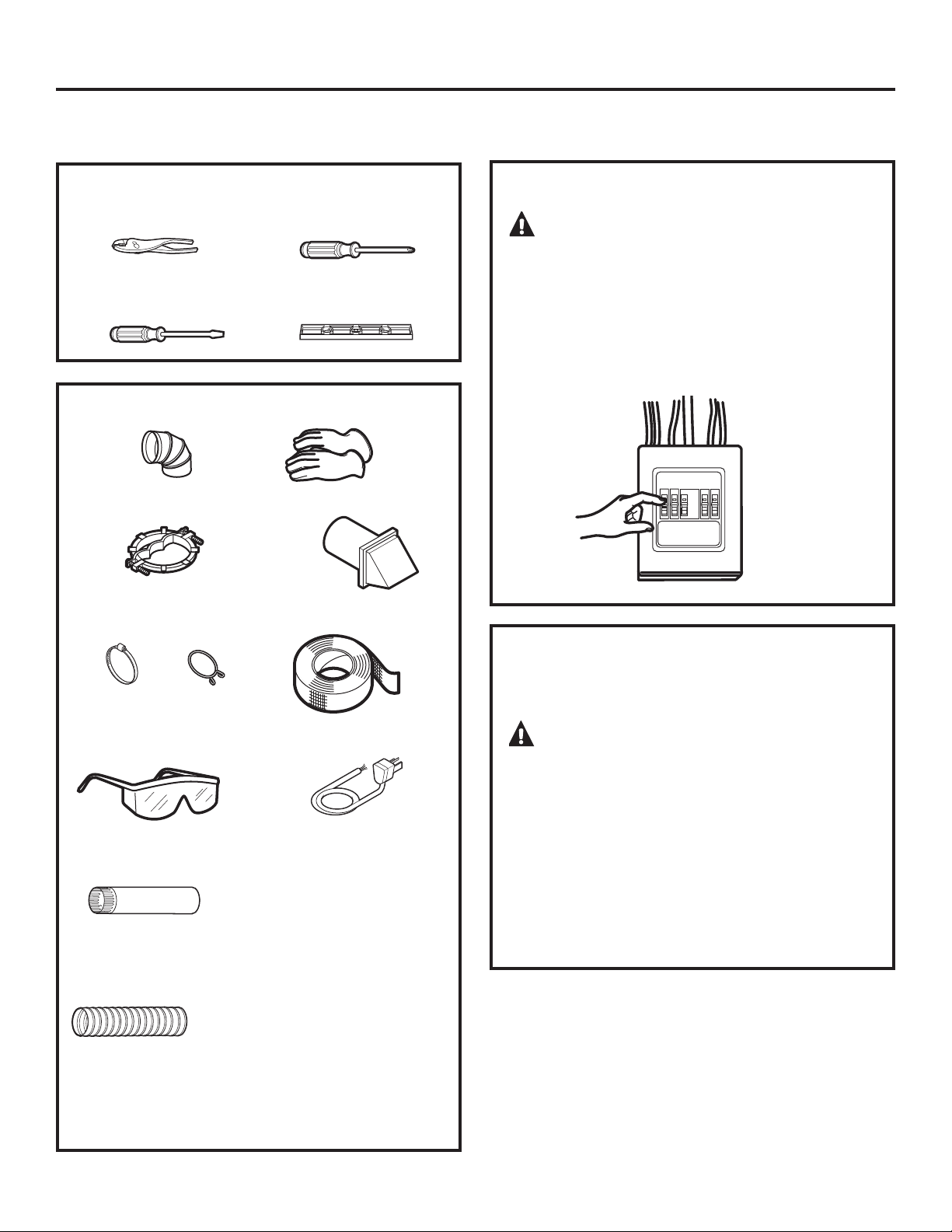
Instructions d’installation
74
RACCORDEMENT D’UNE SÉCHEUSE ÉLECTRIQUE (non applicable aux
sécheuses à gaz)
RENSEIGNEMENTS SUR LES RACCORDS
ÉLECTRIQUES POUR SÉCHEUSES
ÉLECTRIQUES
POUR VOTRE SÉCURITÉ:
AVERTISSEMENT
Avant d’effectuer le branchement électrique,
déclenchez le disjoncteur ou enlevez le fusible de
la sécheuse au panneau de distribution électrique.
Assurez-vous que le cordon d’alimentation de la
sécheuse est débranché de la prise murale. NE
LAISSEZ JAMAIS LE CAPOT DE LA PLAQUE À BORNES
ENLEVÉ.
Pince à joint coulissant
Tournevis à tête plate
Tournevis cruciforme
Niveau
OUTILS NÉCESSAIRES
Coude métallique 4
po diamètre
Réducteur de tension
3/4 po (UL)
Colliers de conduit
4 po (2) ou brides à
ressort 4 po (2)
Lunettes de
protection
Tuyau métallique
4 po de diamètre
(recommandé)
Tuyau métallique
souple 4 po
de diamètre (si
nécessaire)
Gants
L’event d’évacuation
Ruban adhésif
Cordon
d’alimentation de la
sécheuse (non livré
avec l’appareil)
Conforme à la
norme UL 120/240
V, 30 A avec 3 ou 4
broches. Identifiez le
type de fiche selon
la prise murale de
votre domicile avant
d’acheter le cordon.
MATÉRIEL NÉCESSAIRE
AVERTISSEMENT – Pour réduire
les risques d’incendie, de chocs électriques ou de
blessure:
•
N’utilisez pas de rallonge électrique ou
d’adaptateur de prise avec cette machine.
•
Cette sécheuse doit être mise à la terre en
conformité avec les codes et règlements locaux,
ou en l’absence de codes locaux, en conformité
avec le CODE NATIONAL DE L’ÉLECTRICITÉ, ANSI/
NFPA° 70, ou au Canada la norme CSA C22.1 du
Code canadien de l’électricité, 1
re
partie.
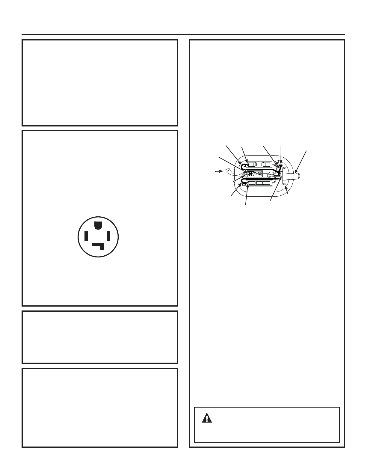
Instructions d’installation
75
Cette sécheuse doit être raccordée à un circuit
domestique indépendant, protégé par un
disjoncteur ou un fusible temporisé. Un circuit
monophasé de 120/240 V ou 120/208V, 60 Hz et
30 ampères, à trois ou quatre fils, est nécessaire.
Si l’alimentation électrique fournie n’est pas
conforme aux exigences ci-dessus, contactez alors
un électricien qualifié.
La sécheuse doit être branchée à un réseau de
fils en métal permanents et mis à la terre; ou
un conducteur de mise à la terre doit suivre les
conducteurs du circuit et être branché à la borne de
mise à la terre sur la sécheuse.
REMARQUE: Depuis le 1
er
janvier 1996, le Code national de
l’électricité impose aux nouvelles constructions d’utiliser
un raccordement à 4 fils pour une sécheuse électrique.
Un cordon à 4 fils doit aussi être utilisé lorsque les normes
locales n’autorisent pas une mise à la terre via le neutre.
Un raccordement à 3 fils NE doit PAS être utilisé dans
une nouvelle construction.
AVERTISSEMENT – NE
LAISSEZ JAMAIS LE COUVERCLE ENLEVÉ DE LA
PLAQUE À BORNES.
1. Déclenchez le(s) disjoncteurs(s) ou retirez le(s)
fusible(s) du circuit du tableau électrique.
2.
Assurez-vous que le cordon de la sécheuse est
débranché de la prise murale.
3.
Retirez le couvercle du cordon d’alimentation
situé à l’arrière.
4.
Retirez et jetez la languette de mis à la terre.
Conserver la vis verte de mise à la terre pour
l’étape 7.
5.
Insérez un réducteur de tension conforme UL 3/4
po dans le trou d’entrée du cordon. Faites passer
le cordon d’alimentation dans le réducteur de
tension.
6.
Connectez le cordon d’alimentation comme suit:
A. Connectez les 2 fils sous tension aux vis
extérieures de la plaque à bornes (L1 et L2).
B. Connectez le fil neutre (blanc) au centre de la
plaque à bornes (N).
7.
Branchez le fil de terre du cordon à la vis verte de
mise à la terre (trou placé au-dessus du support
du réducteur de tension). Serrez toutes les vis de
la plaque à bornes (3) fermement.
8.
Fixez le cordon d’alimentation dans le réducteur
de tension.
9.
Réinstallez le couvercle.
4 conducteurs
en cuivre N°
10 minimum
ou cordon
d’alimentation
de 120/240
V 30 A pour
sécheuse
muni de
cosses
ouvertes ou
à anneau
(non fourni)
Fil sous
tension
Fil
vert
Réinstallez la
vis de mise à
la terre verte
à cet endroit
Neutre
(blanc)
Réducteur
de tension
3/4 po (UL)
Support
du
réducteur
de tension
Vis
Retirez et
jetez la
languette
de mise
à la terre.
Conservez
la vis de
mise à
la terre
verte.
Vis
Vis
Fil sous
tension
BRANCHEMENT DE LA SÉCHEUSE À L’AIDE
D’UN CÂBLE À 4 FILS (À UTILISER POUR
L’INSTALLATION DANS UNE MAISON MOBILE)
Cette sécheuse doit être branchée à un circuit
individuel protégé par des fusibles à retardement
ou des disjoncteurs.
Le circuit électrique doit :
1-Étre de 120/240 volts ou 120/208 volts, de 60 Hz,
doté d’une prise murale comme celle ci-dessous :
2-Étre protégé par un disjoncteur ou des fusibles
de 30A.
3- Étre convenablement mis à la terre.
EXIGENCES RELATIVES À L’ÉLECTRICITÉ
POUR LES SÉCHEUSES ÉLECTRIQUES
EXIGENCES RELATIVES À L’ÉLECTRICITÉ
POUR LES SÉCHEUSES ÉLECTRIQUES
(CANADA)
PRISE TYPIQUE 30 AMP
POUR SECHEUSE
G
XY
W
MISE À LA TERRE (CANADA)
Cet appareil doit être mis à la terre. Dans l’événement
d’une malfonction ou bris, la mise à la terre réduirait
le risque de choc électrique en fournissant une voie
de faible résistance électrique pour le courant.
Cet appareil est muni d’un cordon électrique équipé
d’un conducteur et prise servant à la terre. La prise
doit être connectée à un récepteur compatible,
conforme aux exigences et normes locales.
MISE À LA TERRE
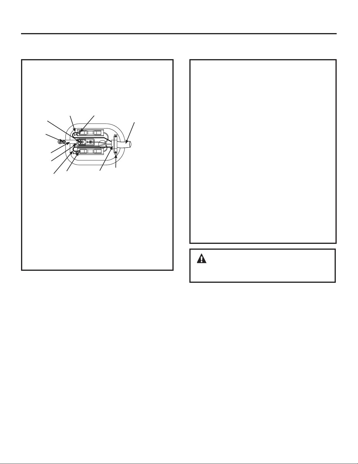
Instructions d’installation
76
RACCORDEMENT DE LA SÉCHEUSE À
L’AIDE D’UN CÂBLE À 3 FILS
1. Déclenchez le(s) disjoncteurs(s) ou retirez le(s)
fusible(s) du circuit du tableau électrique.
2.
Assurez-vous que le cordon de la sécheuse est
débranché de la prise murale.
3.
Retirez le couvercle du cordon d’alimentation
situé à l’arrière.
4.
Insérez un réducteur de tension conforme
UL 3/4 po dans le trou d’entrée du cordon.
Faites passer le cordon d’alimentation dans le
réducteur de tension.
5.
Connectez le cordon d’alimentation comme
suit :
A. Connectez les 2 fils sous tension aux vis
extérieures de la plaque à bornes (L1 et L2).
B. Connectez le fil neutre (blanc) au centre de
la plaque à bornes (N).
6.
Veillez à ce que la languette de mise à la terre
soit connectée à la borne neutre (centre) de la
plaque à bornes et à la vis verte de mise à la
terre sur le boîtier. Serrez toutes les vis de la
plaque à bornes (3) fermement.
7.
Fixez le cordon d’alimentation dans le réducteur
de tension.
8.
Réinstallez le couvercle.
AVERTISSEMENT – NE LAISSEZ
JAMAIS LE COUVERCLE ENLEVÉ DE LA PLAQUE À
BORNES.
RACCORDEMENT D’UNE SÉCHEUSE ÉLECTRIQUE (suite)
Connexion à 3 fils
Ne peut pas être utilisée au Canada.
Ne peut pas être utilisée dans une maison mobile.
Ne peut pas être utilisée dans les nouvelles
constructions.
Ne peut pas être utilisée dans les véhicules
récréatifs.
Ne peut pas être utilisée dans les régions où les
codes locaux interdisent la mise à la terre par le
biais du câble neutre.
3 conducteurs
en cuivre N°
10 minimum
ou cordon
d’alimentation
de 120/240
V 30 A pour
sécheuse muni
de cosses
ouvertes ou à
anneau (non
fourni)
Fil sous tension
Fil sous
tension
Vis verte de
mise à la
terre
Neutre
(blanc)
Réducteur
de tension
3/4 po (UL)
Support
du
réducteur
de tension
Vis
Vis
Vis
Faites installer, si le code local l’exige, une mise à la terre
externe (non fournie) sur un tuyau d’eau froide métallique
mis à la terre ou toute autre mise à la terre par un électricien
qualifié.
Languette
de mise à
la terre
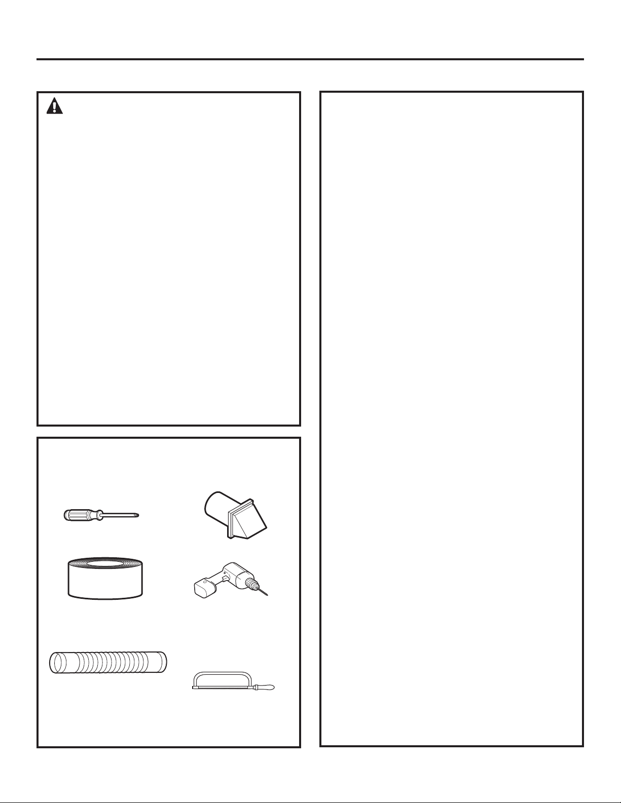
ÉVACUATION DE LA SÉCHEUSE
Instructions d’installation
AVERTISSEMENT – Pour réduire
le risque d’incendie et de blessure :
•
L’air de cette sécheuse doit être évacué à l’extérieur.
•
Utilisez un conduit métallique.
•
Ne faites pas aboutir l’évacuation dans une cheminée,
une ventilation de gaz, sous un sol confiné, dans
un vide sanitaire, un mur, un plafond, dans un
grenier ou tout autre espace confiné d’un bâtiment.
L’accumulation de charpie peut créer un risque
potentiel d’incendie.
•
Prévoyez libre un accès pour l’inspection et le
nettoyage du système d’évacuation, notamment
pour les coudes. Inspectez et nettoyez le système au
moins une fois par an.
L’accumulation de charpie peut
créer un risque potentiel d’incendie.
• Ne terminez jamais l’évacuation dans un conduit
commun avec une évacuation de cuisine. Une
combinaison de charpie et de graisse peut créer un
risque potentiel d’incendie.
•
N’obstruez pas l’entrée ou l’évacuation de l’air.
•
La sécheuse est préparée pour une évacuation de
l’air par l’arrière. Si l’espace est insuffisant, utilisez les
instructions figurant sur les pages 79–81 pour évacuer
l’air par les côtés ou le dessous de la carrosserie.
LISTE DE VÉRIFICATION DU SYSTÈME
D’ÉVACUATION
ÉVENT MURAL
•
Terminez le conduit de façon à éviter les retours
d’air ou l’entrée d’oiseaux ou d’autres animaux.
•
La terminaison doit présenter une résistance
minimale au flux d’air évacué et nécessiter peu
ou pas de maintenance pour empêcher les
obstructions.
•
N’installez jamais un filtre dans ou sur le conduit
d’évacuation.
•
Les évents muraux doivent être installés à au
moins 30,5 cm (12 po) au-dessus du niveau du
sol ou toute autre obstruction avec l’ouverture
dirigée vers le bas.
•
Si des aérations de toiture ou des ventilations
ajourées sont utilisées, elles doivent être
équivalentes à un évent mural à volet de 10,2
cm (4 po) pour ce qui concerne la résistance
au flux d’air, la prévention des retours d’air et
la maintenance nécessaire pour empêcher les
obstructions.
SÉPARATIONS DES COUDES
•
Pour de meilleures performances, séparez tous
les coudes par un conduit droit d’au moins 1,2 m
(4 pieds), y compris sur la distance entre le dernier
coude et
le couvert du tuyau d’échappement.
ÉTANCHÉITÉ DES JOINTS
•
Tous les joints doivent être serrés pour éviter
les fuites. L’extrémité mâle de chaque section
du conduit doit être dirigée vers l’extérieur par
rapport à la sécheuse.
•
N’assemblez pas les conduits avec des fixations
qui pénètrent dans le conduit. Elles serviraient de
point de collecte pour la charpie.
•
Les joints de conduit doivent être étanches à l’air
et à la poussière, recouverts de ruban de toile ou
en aluminium.
•
Les conduits horizontaux doivent être inclinés
vers l’extérieur de 6 mm (1/4 po) par pied de
longueur.
ISOLATION
•
Les conduits qui traversent une zone non
chauffée ou situés à proximité d’un climatiseur
doivent être isolés pour réduire la condensation
et la création de charpie.
77
OUTILS ET MATÉRIEL NÉCESSAIRES
À L’INSTALLATION DU CONDUIT
D’ÉVACUATION
Tournevis cruciforme
Ruban de toile ou
colliers pour conduit
Conduit métallique
rigide ou souple
homologué UL de 10,2
cm (4 po)
Évent d’évacuation
Percez à l’aide d’un
foret de 1/8 po (pour
évacuation par le
dessous)
Scie à métaux
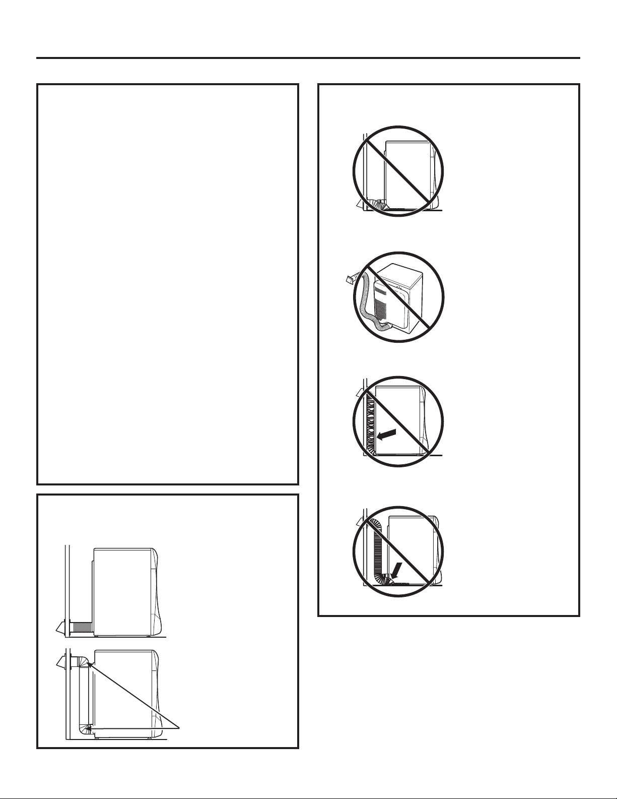
ÉVACUATION DE LA SÉCHEUSE (suite)
Instructions d’installation
78
UTILISATION D’UN CONDUIT
MÉTALLIQUE SOUPLE POUR
L’ÉVACUATION TRANSITOIRE
L’utilisation de conduits métalliques rigides ou semi-
rigides est recommandée pour l’évacuation transitoire
entre la sécheuse et le mur. Dans les installations
spéciales où il est impossible d’effectuer un raccordement
conforme aux recommandations précédentes, alors un
conduit métallique souple transitoire homologué UL
peut être utilisé entre la sécheuse et le mur uniquement.
L’utilisation de ce type de conduit affectera la durée du
séchage. Le fabricant ne reconnaît que ces types de
conduits souples comme étant spécialement conçus
pour être utilisés avec la machine. Aux États-Unis, le
conduit doit être conforme à la norme Outline for Clothes
Dryer Transition Duct (Directives générales concernant le
conduit de transition des sécheuses de linge, chapitre
2158A).
Si un conduit métallique souple transitoire se révèle
nécessaire, les consignes suivantes doivent être
respectées :
• Utilisez la plus petite longueur possible. La longueur
totale de conduit métallique souple ne dépassera pas 2.4 m.
• Étirez le conduit à sa longueur maximale.
• Ne l’écrasez pas ou ne le pliez pas.
• N’utilisez jamais de conduit métallique souple dans le
mur ou à l’intérieur de la sécheuse.
• Évitez de poser le conduit sur des objets pointus.
• L’évacuation doit être conforme aux normes locales
de construction.
POUR L’ÉVACUATION TRANSITOIRE (DE LA
SÉCHEUSE AU MUR), FAITES:
• COUPEZ
le conduit aussi
court que possible
et installez-le droit
vers le mur.
•
UTILISEZ des
coudes lorsque
des changements
de direction sont
nécessaires.
NE FAITES PAS:
• N’ÉCRASEZ PAS
ou ne pliez pas le
conduit. Utilisez
des coudes lorsque
des changements
de direction sont
nécessaires.
•
N’UTILISEZ PAS une
longueur excessive
de conduit. Coupez le
conduit aussi court que
possible.
• N’ÉCRASEZ PAS
le conduit contre le
mur.
•
N’INSTALLEZ PAS
la sécheuse sur le
conduit.
Coudes
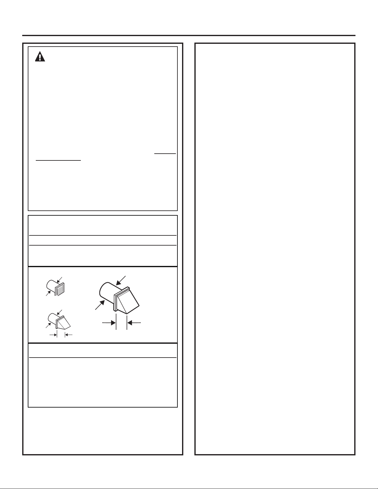
Instructions d’installation
LISTE DE VÉRIFICATION DU SYSTÈME
D’ÉVACUATION
ÉVENT MURAL
• Terminez le conduit de façon à éviter les retours
d’air ou l’entrée d’oiseaux ou d’autres animaux.
• La terminaison doit présenter une résistance
minimale au flux d’air évacué et nécessiter peu
ou pas de maintenance pour empêcher les
obstructions.
• N’installez jamais un filtre dans ou sur le
conduit d’évacuation. Ceci pourrait causer une
accumulation de charpie.
• Les évents muraux doivent être installés à au
moins 30,5 cm (12 po) au-dessus du niveau du sol
ou toute autre obstruction avec l’ouverture dirigée
vers le bas.
• Si des aérations de toiture ou des ventilations
ajourées sont utilisées, elles doivent être
équivalentes à un évent mural à volet de 10,2 cm (4
po) pour ce qui concerne la résistance au flux d’air,
la prévention des retours d’air et la maintenance
nécessaire pour empêcher les obstructions.
SÉPARATIONS DES COUDES
Pour de meilleures performances, séparez tous les
tours par au moins 4 pi de conduits droit, incluant la
distance entre le dernier tour et le couvert du tuyau
d’échappement.
AUTRES TOURS QUE 90º
• Un tour de 45º ou moins peut être ignoré.
• Deux tours de 45º devraient être considérés
comme un tour de 90º.
• Chaque tour de plus de 45º devrait être traité
comme un tour de 90º.
ÉTANCHÉITÉ DES JOINTS
• Tous les joints doivent être serrés pour éviter les
fuites. L’extrémité mâle de chaque section du
conduit doit être dirigée vers l’extérieur par rapport
à la sécheuse.
• N’assemblez pas les conduits avec des fixations
qui pénètrent dans le conduit. Elles serviraient de
point de collecte pour la charpie.
• Les joints de conduit doivent être étanches à l’air et
à la poussière, recouverts de ruban de toile.
• Des séries horizontales devraient se diriger vers le
bas, vers l’extérieur 1/4 po par pied.
ISOLATION
•
Les conduits qui traversent une zone non
chauffée ou situés à proximité d’un climatiseur
doivent être isolés pour réduire la condensation
et la création de charpie.
AVERTISSEMENT – N’UTILISEZ
QUE DES CONDUITS DE MÉTAL DE 4 PO. NE PAS
UTILISEZ DES CONDUITS PLUS LONG QUE CE QUI
EST SPÉCIFIÉ DANS LE TABLEAU DE LONGUEUR
D’ÉCHAPPEMENT.
Utilisez des tuyaux d’échappement plus long que ce qui est
spécifié aura comme conséquence :
• Augmentera les temps de séchage et les coûts d’énergie.
• Réduira la durée de vie de la sécheuse.
• Accumulation de la charpie, créant un danger potentiel de
feu.
L’installation correcte du tuyau est VOTRE
RESPONSABILITÉ.
Les problèmes causés par une mauvaise installation
ne sont pas couverts par la garantie.
La longueur du système d’échappement MAXIMUM PERMISE
dépend du type de conduits, du nombre de tours, du type de
couvert de tuyau d’échappement (couvert mural) et de toutes
les conditions mentionnées ci-dessus.
LONGUEUR DU TUYAU D’ÉCHAPPEMENT
LONGUEUR MAXIMUM RECOMMANDÉ
Types de couverts de tuyau d’échappement
Recommandé Utilisation pour des
installations de courte
durée seulement
Nombre de Métal Métal
Coudes à 90º rigide rigide
0 150 pieds 125 pieds
1 135 pieds 115 pieds
2 125 pieds 105 pieds
3 115 pieds 95 pieds
4 105 pieds 85 pieds
5 95 pieds 75 pieds
4 po
2
1
ø2 po
4 po de diamètre
4 po de diamètre
4 po de diamètre
79
• Pour chaque coude additionnel de 90°, réduire de 10 pieds la
longueur totale permise du système de ventilation.
• Deux coudes de 45° devront être considérés comme un coude
de 90°.
• Pour la ventilation latérale, ajouter un coude de 90° au tableau.
• La longueur totale du système de ventilation inclut toutes les
portions droites et tous les coudes du système (le tuyau de
transition inclus).
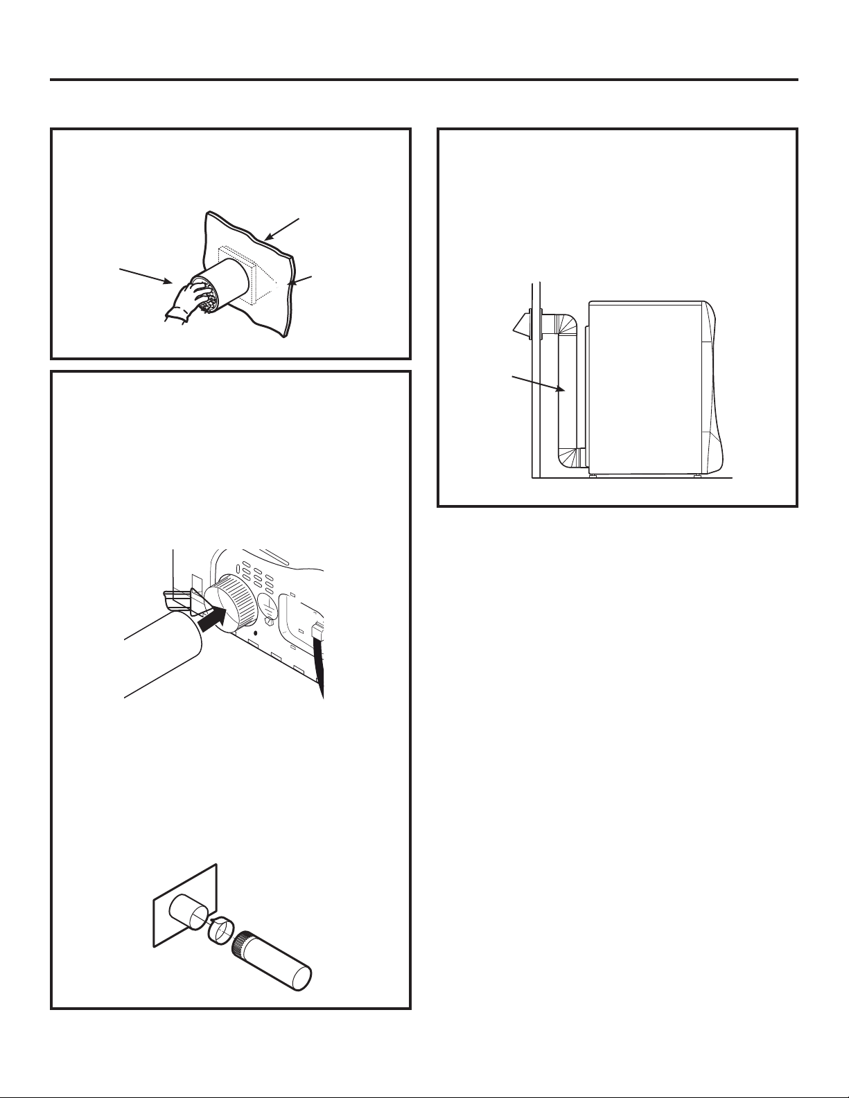
ÉVACUATION DE LA SÉCHEUSE (suite)
Instructions d’installation
80
AVANT DE COMMENCER
Enlevez toute charpie de l’ouverture d’évacuation
murale.
Ouverture
du conduit
interne
Mur
Vérifiez que le
volet de l’évent
mural s’ouvre
et se ferme
librement.
ÉVACUATION ARRIÈRE STANDARD
Nous vous recommandons d’installer votre
sécheuse avant d’installer votre laveuse. Cela
permettra un accès direct pour faciliter le
raccordement de l’évacuation.
Insérez l’extrémité du conduit d’évacuation sur le
raccord arrière de la sécheuse et fixez-la avec du
ruban de toile ou un collier de fixation.
REMARQUE: Nous vous recommandons fortement
d’utiliser un conduit d’évacuation rigide et en métal.
Si vous utilisez un conduit métallique semi-rigide,
coupez-le à la bonne longueur et évitez d’écraser le
conduit derrière la sécheuse.
•
Pour une installation droite, raccordez le conduit
d’évacuation de la sécheuse au mur l’aide de
ruban en toile.
CONFIGURATION RECOMMANDÉE
POUR MINIMISER UN BLOCAGE
DU CONDUIT
L’utilisation de coudes empêchera les conduits de
se déformer et de s’écraser.
Conduit
Conduit
transitoire
Côté mur
Côté
sécheuse
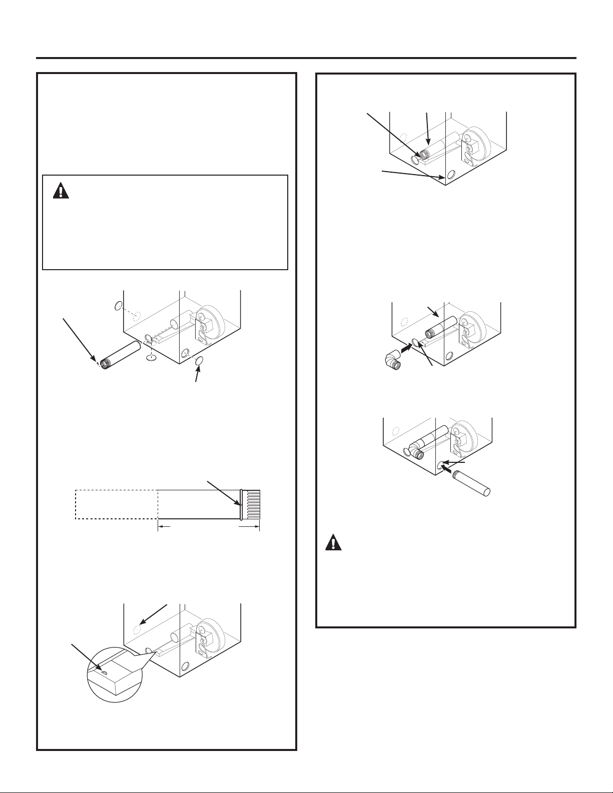
AVERTISSEMENT –
AVANT DE
PROCÉDER À L’INSTALLATION DE L’ÉVACUATION,
VEILLEZ À COUPER L’ALIMENTATION ÉLECTRIQUE DE
LA SÉCHEUSE. PROTÉGEZ VOS MAINS ET VOS BRAS DES
PARTIES COUPANTES LORQUE VOUS TRAVAILLEZ SUR
LA CARROSSERIE. MUNISSEZ-VOUS DE GANTS.
Instructions d’installation
81
ÉVACUATION LATÉRALE:
Orifice d’évacuation de la sécheuse sur la droite de la
carrosserie sur les modèles fonctionnant à l’électricité
uniquement.
Orifice d’évacuation de la sécheuse sur la gauche de
la carrosserie sur les modèles fonctionnant au gaz et
à l’électricité.
Enlevez la débouchure gauche, droite ou du dessous.
Retirez la vis située à l’intérieur du tuyau d’évacuation
de la sécheuse et conservez-la. Retirez le tuyau de la
sécheuse.
Retirez la vis
et mettez-la
de côté
Retirez la débouchure
appropriée (une seule)
Trou de fixation
Coupez le tuyau comme indiqué et conservez
la portion A.
EMPLACEMENT DE LA LANGUETTE
Pliez la
languette
à un angle
de 45°
À travers l’orifice arrière, repérez la languette au
milieu de la base de l’appareil. Soulevez la languette
à 45° à l’aide d’un tournevis à tête plate.
AJOUTER UN NOUVEAU CONDUIT
Rebranchez la portion découpée (A) du conduit au
boîtier du ventilateur. Veillez à ce que le conduit
raccourci soit aligné sur la languette dans la base.
Utilisez la vis mise de côté précédemment pour fixer le
conduit à la languette sur la base de l’appareil.
AJOUTER UN COUDE ET UN CONDUIT POUR
L’ÉVACUATION SUR LA GAUCHE ET LA DROITE DE
L’APPAREIL
• Introduisez le coude de 4 po dans l’orifice arrière
et connectez le coude au tuyau interne de la
sécheuse.
• Introduisez le conduit de 4 po dans l’orifice latéral
et connectez-le au coude.
MISE EN GARDE: Ne pas tirer ou
endommager les fils électriques et ne pas retirer le
couvert de vinyle des pièces électriques à l’intérieur
de la sécheuse lors de l’insertion du conduit. Une
légère interférence peut se produire entre
l’évacuation et les composants de fil.
Portion « A »
Évacuation
côté gauche
Trou de fixation
Tuyau interne
Non applicable au gaz
A
34,3 cm (13
1
ø2 po)
Droite
Gauche
Dessous
Orifice arrière
Orifice latéral
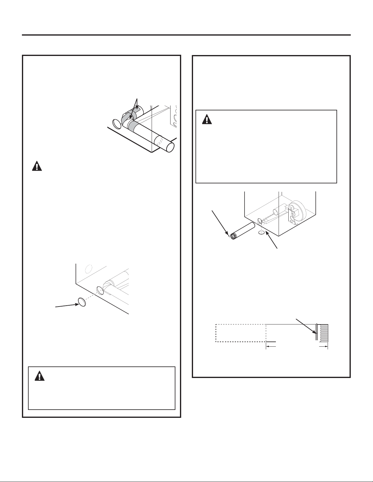
ÉVACUATION DE LA SÉCHEUSE (suite)
Instructions d’installation
82
ÉVACUATION LATÉRALE (suite)
AVERTISSEMENT – IL FAUT
TOUJOURS LAISSER LA PLAQUE D’OBTURATION
SUR L’ORIFICE À L’ARRIÈRE DE LA SÉCHEUSE.
(Ensemble WE1M454)
Connectez les coudes et les conduits métalliques
pour terminer l’installation du système d’évacuation.
Recouvrez l’orifice arrière d’une plaque (Ensemble
WE1M454) disponible auprès de votre fournisseur
local. Placez la sécheuse à son emplacement final.
AJOUTER UNE PLAQUE D’OBTURATION À
L’ARRIÈRE DE LA CARROSSERIE (ÉVACUATION
LATÉRALE)
Plaque
(Ensemble WE1M454)
AJOUTER UN COUDE ET UN CONDUIT POUR
L’ÉVACUATION SUR LA GAUCHE ET LA DROITE
DE L’APPAREIL (suite)
• Appliquez du ruban
adhésif comme indiqué
sur le joint entre le
tuyau interne de la
sécheuse et le coude,
et également sur le
joint entre le coude et
le tuyau latéral.
ATTENTION: UTILISEZ UN CONDUIT
MÉTALLIQUE RIGIDE DE 10 CM UNIQUEMENT À
L’INTÉRIEUR DE LA SÉCHEUSE.
LES JONCTIONS DE CANALISATION INTERNE
DOIVENT ÊTRE BLOQUÉES AVEC UN RUBAN
ADHÉSIF, SINON ELLES PEUVENT SE SÉPARER ET
POSER UN DANGER POUR LA SÉCURITÉ.
Ruban adhésif
AVERTISSEMENT – AVANT
DE PROCÉDER A L’INSTALLATION DU
SYSTEME D’ÉVACUATION, VEILLEZ À COUPER
L’ALIMENTATION ÉLECTRIQUE DE LA
SÉCHEUSE. PROTÉGEZ VOS MAINS ET VOS
BRAS DES PARTIES COUPANTES LORQUE
VOUS TRAVAILLEZ SUR LA CARROSSERIE.
MUNISSEZ-VOUS DE GANTS.
ÉVACUATION PAR LE DESSOUS:
Orifice d’évacuation de la sécheuse par le
dessous de la carrosserie sur les modèles
fonctionnant au gaz et à l’électricité.
Retirez la vis située à l’intérieur du tuyau d’évacuation
de la sécheuse et conservez-la. Retirez le tuyau de
la sécheuse. Enlevez la débouchure du dessous.
Retirez la vis
et mettez-la
de côté
Retirez la débouchure
appropriée (une seule)
Trou de fixation
Coupez le tuyau comme indiqué et conservez la
portion A.
A
33,7 cm (13
1
ø4 po)
Dessous
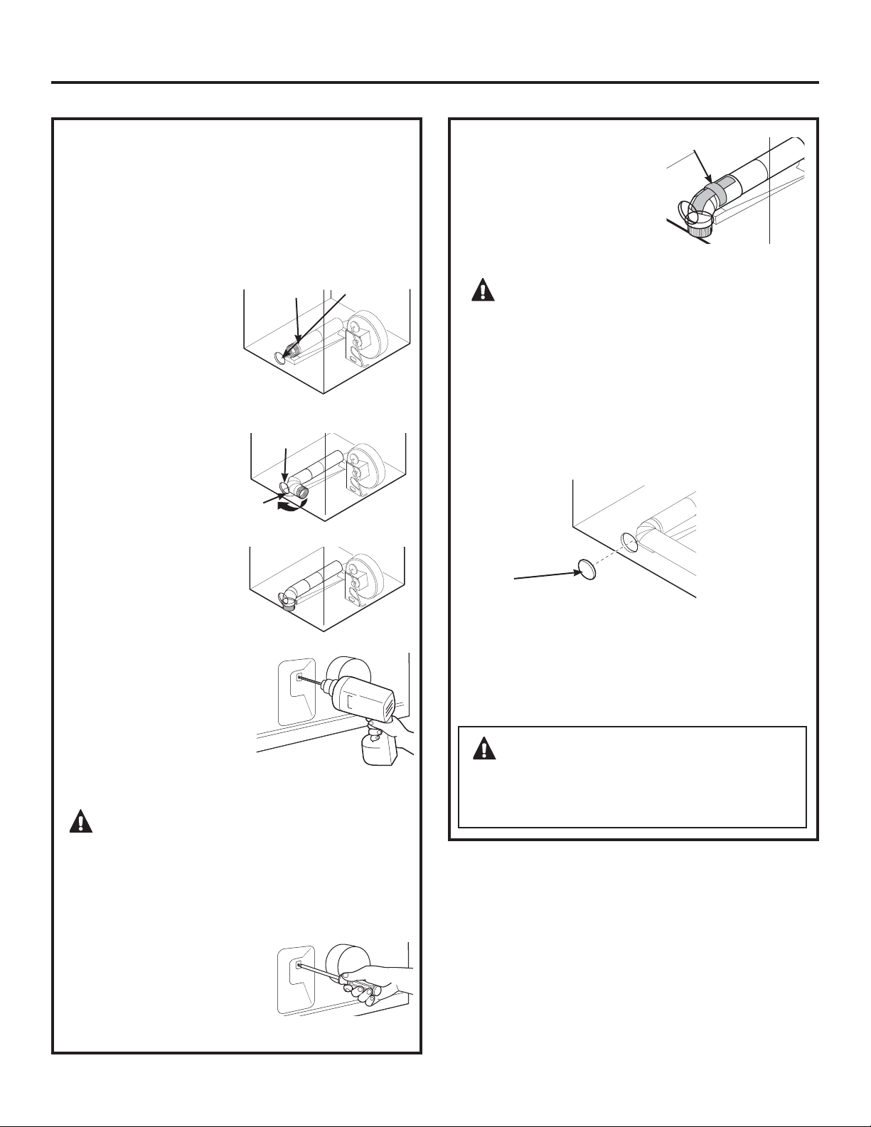
• Rebranchez la portion
découpée A du conduit
u boîtier du ventilateur.
• Placez du ruban adhésif
sur le coude dans un
angle de 90 degrés afin
d’éviter toute rotation.
• Introduisez le coude
dans l’orifice arrière
et connectez-le à la
portion A. Pivotez le
coude vers l’orifice du
dessous.
• Tout en tenant le tuyau
et le coude à l’aide de
vos mains via l’orifice
arrière, percez un trou
de 1/8 po à travers le
trou de la languette
inférieure et le tuyau
conformément à
l’illustration.
REMARQUE: Assurez-vous
que la perceuse a traversé le tuyau et le coude.
MISE EN GARDE : Prenez soin de ne
pas tirer ou endommager les fils électriques placés à
l’intérieur de la sécheuse lors de l’insertion du
conduit.
AVERTISSEMENT – IL FAUT
TOUJOURS LAISSER LA PLAQUE D’OBTURATION
SUR L’ORIFICE À L’ARRIÈRE DE LA SÉCHEUSE.
(Ensemble WE1M454)
ÉVACUATION PAR LE DESSOUS (suite)
Orifice d’évacuation de la sécheuse par le
dessous de la carrosserie sur les modèles
fonctionnant au gaz et à l’électricité.
Connectez les coudes et les conduits métalliques
pour terminer l’installation du système d’évacuation.
Recouvrez l’orifice arrière d’une plaque (Ensemble
WE1M454) disponible auprès de votre fournisseur
local. Placez la sécheuse à son emplacement final.
AJOUTER UNE PLAQUE D’OBTURATION À
L’ARRIÈRE DE LA CARROSSERIE (ÉVACUATION
PAR LE DESSOUS)
Plaque
(Ensemble WE1M454)
Instructions d’installation
83
AJOUTER UN NOUVEAU CONDUIT
• Tout en tenant le tuyau
et le coude par l’orifice
arrière, vissez les tuyaux
en place à l’aide de la vis
précédemment mise de
côté.
Orifice
arrière
Orifice
du dessous
Vue de dessous
Portion « A »
Trou de
fixation
• Appliquez du ruban adhésif
sur le joint entre le tuyau
interne de la sécheuse et le
coude.
REMARQUE: Assurez-vous
que le ruban recouvre le
trou de vis de la portion A à
l’endroit où il se raccorde au coude.
MISE EN GARDE: Les joints du
conduit interne doivent être fixés avec du ruban
adhésif afin d’éviter qu’ils ne se détachent et que
ceci n’entraîne un risque pour la sécurité.
Ruban adhésif
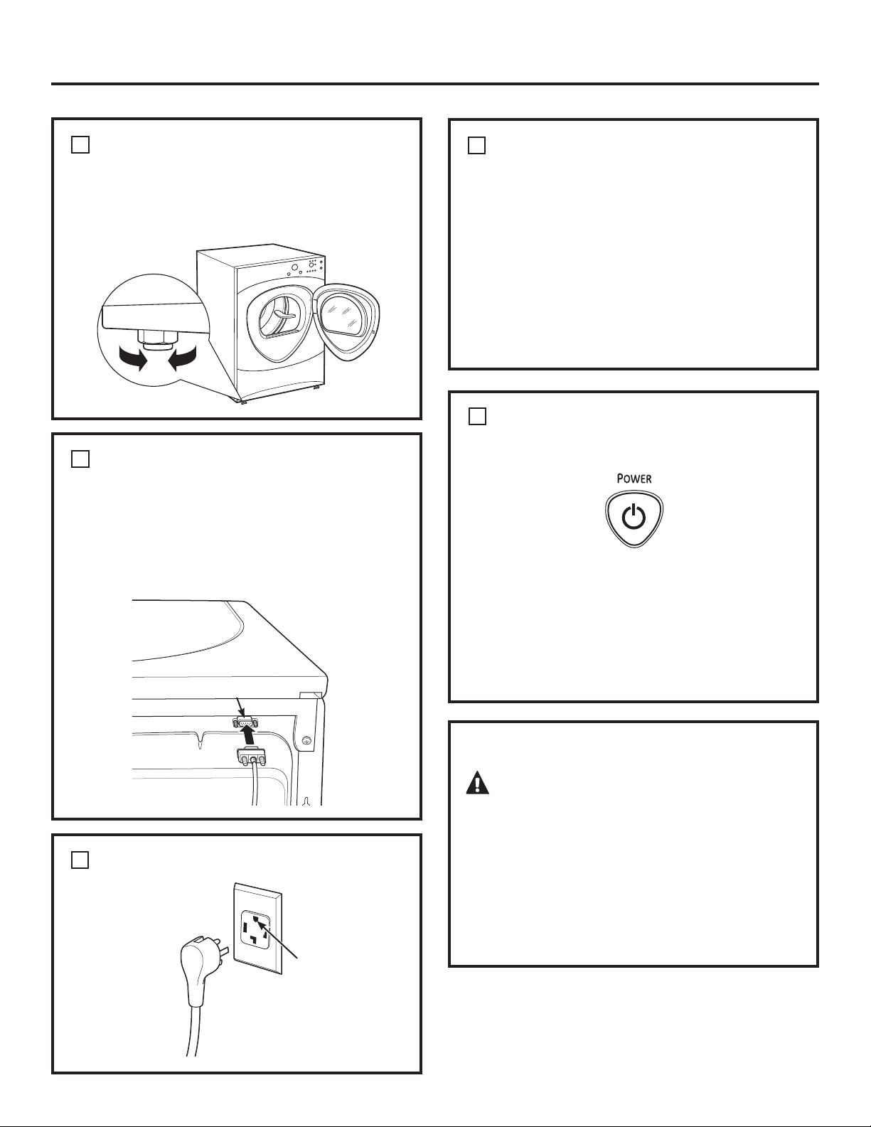
DÉMARRAGE DE LA SÉCHEUSE
Appuyez sur la touche POWER (ALIMENTATION).
REMARQUE: Si la sécheuse a été exposée à des
températures inférieures au point de congélation
pendant une période prolongée, laissez-la
se réchauffer avant d’appuyer sur POWER
(ALIMENTATION). Sinon, l’écran ne s’allumera pas.
La sécheuse est maintenant prête à l’emploi.
MAINTENANCE
AVERTISSEMENT – Étiquetez
tous les câbles avant de les débrancher pour les
réparations. Les erreurs de câblage peuvent
provoquer un fonctionnement inapproprié et
dangereux après une installation/réparation.
Pour les pièces de rechange et les autres
informations, consultez la page 100 du manuel
d’utilisation pour connaître les numéros de
téléphone du service après-vente.
5
Instructions d’installation
METTEZ LA SÉCHEUSE DE NIVEAU
Placez la sécheuse à proximité de l’emplacement
final. Réglez les quatre pattes de nivellement pour la
mettre de niveau de gauche à droite, et de l’avant
vers l‘arrière.
Baisser
Monter
BRANCHEMENT DU CÂBLE SÉRIE
Branchez le câble série pour le raccordement de la
laveuse et de la sécheuse dans le port série placé à
l’arrière de la sécheuse.
Branchez l’autre extrémité du câble sur la laveuse
avant de pousser la laveuse à son emplacement
final.
BRANCHEZ LA SÉCHEUSE
Assurez-vous au
préalable qu’une
mise à la terre
existe bien et
qu’elle fonctionne
correctement.
1
2
INSTALLATION FINALE
3
Arrière de
la sécheuse
Port série
INSTRUCTIONS DE MISE À LA TERRE
Vous devez mettre à la terre cet appareil
électroménager. En cas de panne ou de mau vais
fonctionnement, cette mise à la terre réduira le
risque de secousse électrique en fournissant au
courant un passage de moindre résistance. Cet
appareil est équipé d’un cordon qui est muni d’un
conducteur et d’une fiche de mise à la terre. Cette
fiche doit être branchée dans une bonne prise,
bien installée et mise à la terre conformément à
tous les codes et à toutes les ordonnances locales.
4
84
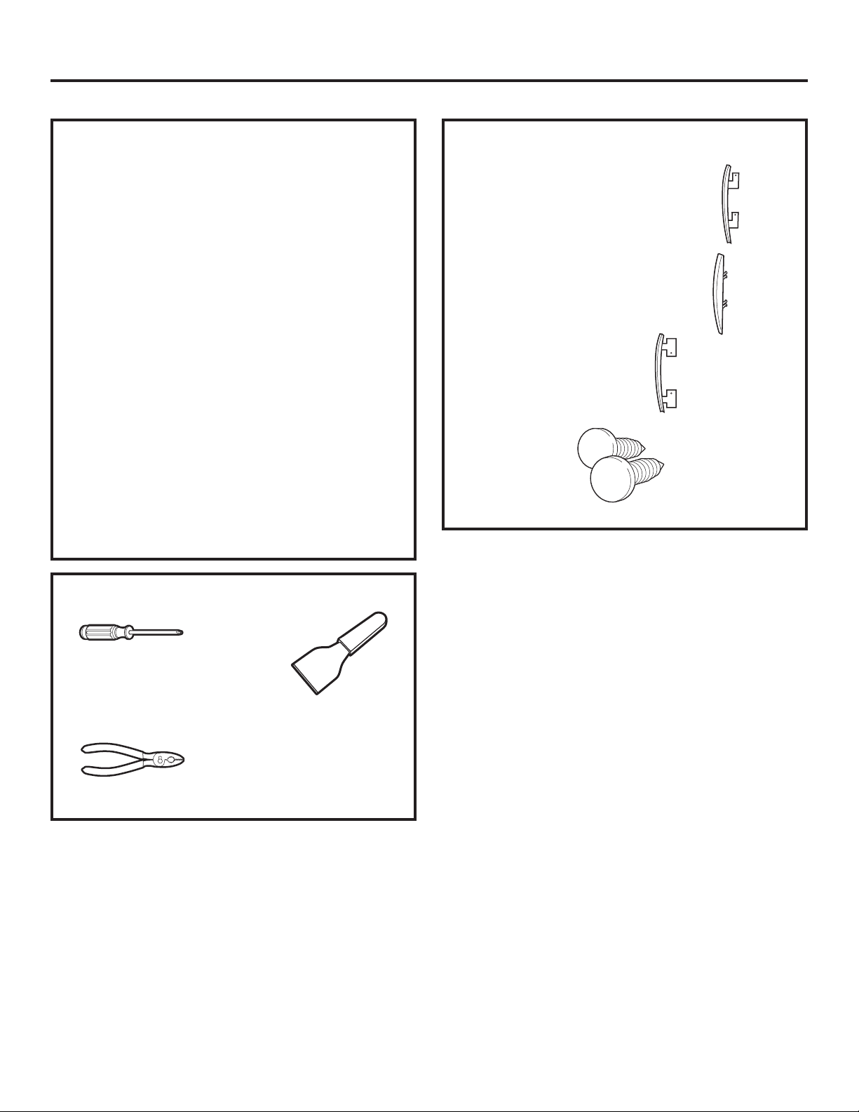
Instructions d’installation
85
REMARQUES IMPORTANTES
• Lisez l’ensemble des instructions avant de
commencer.
• Manipulez les pièces avec soin afin d’éviter
d’abîmer la peinture.
• Prévoyez une surface non abrasive pour les
portes.
• Posez les vis à côté de leurs pièces respectives
afin d’éviter de les utiliser aux mauvais endroits.
• Toutes les vis doivent être vissées à la main.
• La procédure d’inversion de l’ouverture de la
porte dure de 30 à 60 minutes.
IMPORTANT: Après avoir commencé, ne déplacez
pas la sécheuse avant que l’inversion de l’ouverture
de la porte n’ait été effectuée.
Ces instructions permettent de transférer les
charnières du côté droit vers le côté gauche.
Si vous souhaitez les réinstaller du côté droit,
veuillez suivre ces mêmes instructions et inversez
toutes les références aux termes gauche et droite.
OUTILS NÉCESSAIRES
Couvercle de porte chromé
Couvre-charnière de porte chromé
Couvercle de contre-porte
2 capuchons
Tournevis
cruciforme ou
tournevis à tête
quadrex
ENSEMBLE D’INVERSION STANDARD
INVERSION DE L’OUVERTURE DE LA PORTE (optionnel)
Couteau à mastic
ou tournevis à fine
lame
Pince
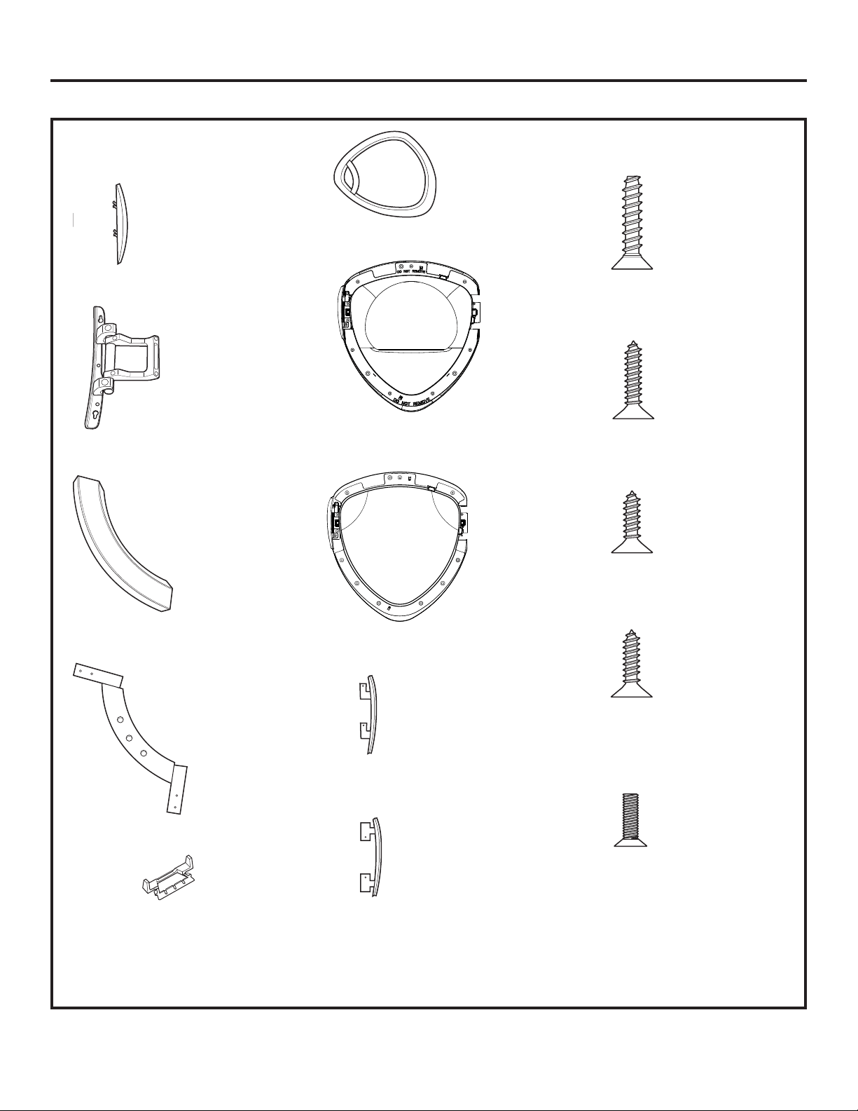
INVERSION DE L’OUVERTURE DE LA PORTE (optionnel) (suite)
PIÈCES DE LA PORTE
Couvre-charnière
Charnière
Poignée externe
Poignée interne
2 capuchons de poignée
Couvercle de porte chromé
Couvercle intérieur (cache)
Hublot
Couvercle de porte chromé
Couvercle de contre-porte
A Grandes vis taraudeuses 7
– #10 x 1,125 po
B Grandes vis taraudeuses 2
– #10 x 0,75 po
C Petite vis taraudeuse 1 – #8
x 0,375 po
D Petites vis taraudeuses 11
– #8 x 0,625 po
E Vis à métaux 4 – #8 x 0,50
po
Instructions d’installation
86
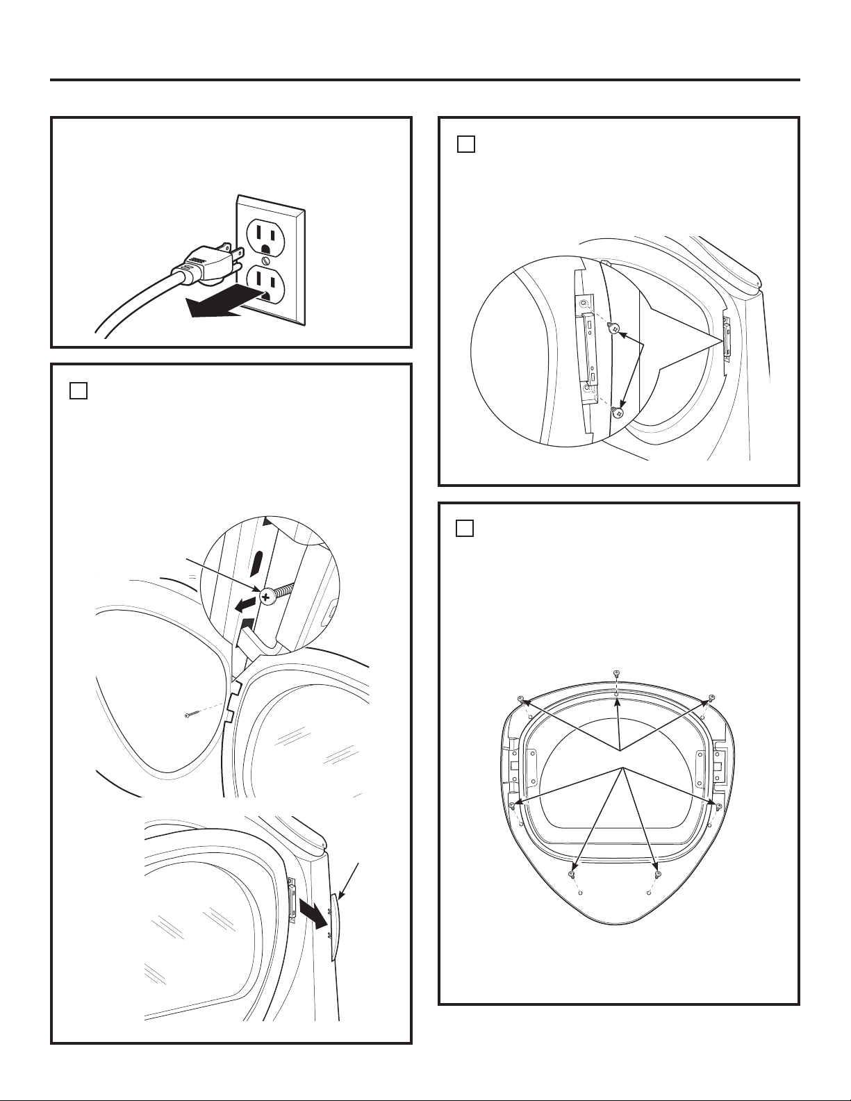
Instructions d’installation
87
COMMENT RETIRER LA PORTE
Retirez le couvre-charnière latéral en ouvrant la
porte de la sécheuse et en retirant la vis placée
derrière la charnière (vis taraudeuse #8 x 0,375
po). Retirez à la main le couvre-charnière de la
sécheuse.
Couvre-
charnière
1
COMMENT DÉMONTER LA PORTE
Déposez la porte sur une surface plane, lisse et
protégée de sorte que la partie intérieure soit
placée vers le haut (la porte est couchée sur le côté
de la poignée).
Retirez les 7 vis (vis taraudeuses #10 x 1,125 po)
situées autour du périmètre de la porte.
2
Retournez la porte et séparez le couvercle chromé
de la contre-porte. Déposez la contre-porte sur une
surface plane, lisse et protégée.
7 x A Vis
AVANT DE COMMENCER
Débranchez la sécheuse de sa prise électrique.
COMMENT RETIRER LA PORTE (SUITE)
1
Fermer et tenir la porte, déposez les 2 vis de
charnière (vis autotaraudeuses No 10 x 0,75 po).
Retirez la porte du panneau avant de la sécheuse.
2 x B Vis
1 x C Vis
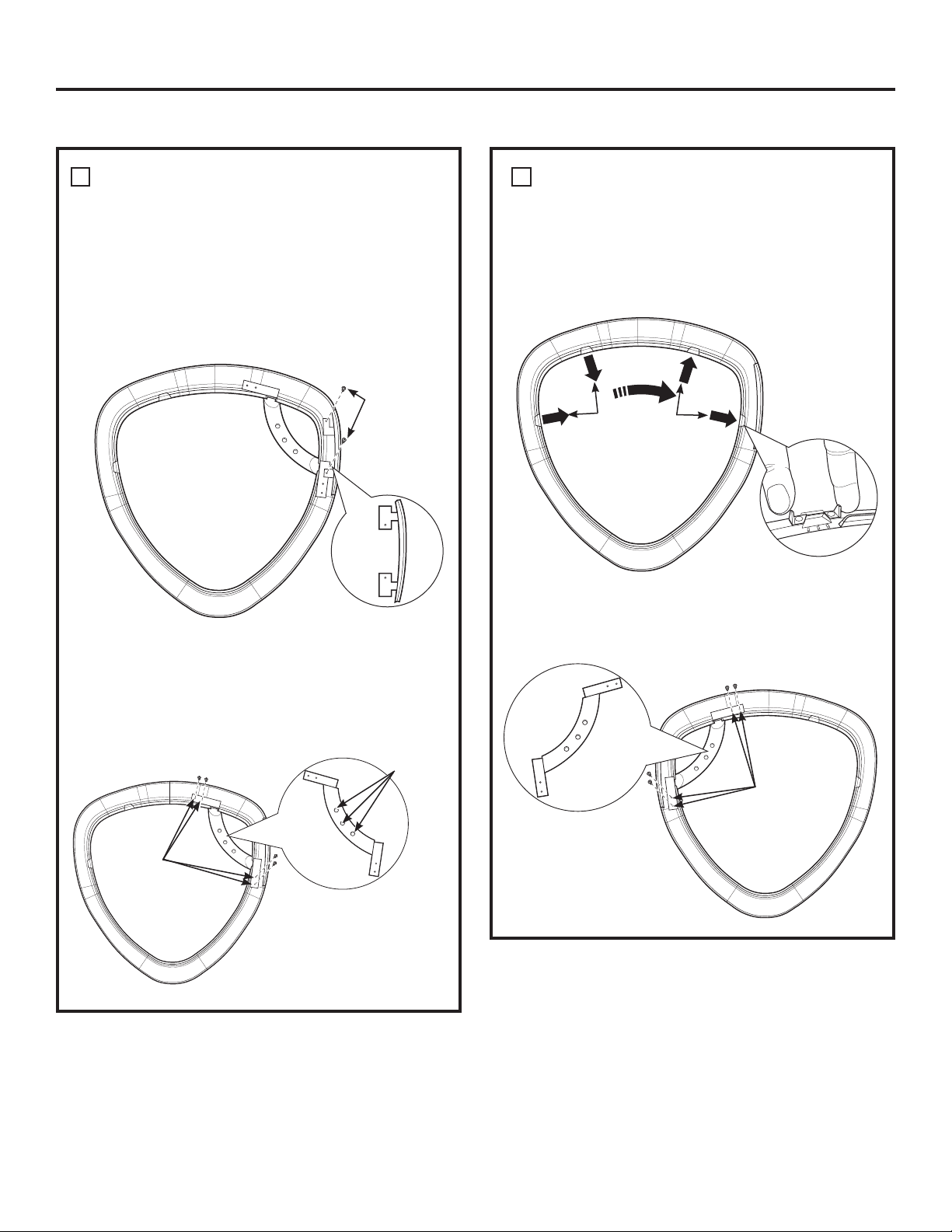
INVERSION DE L’OUVERTURE DE LA PORTE (optionnel) (suite)
COMMENT INVERSER LA POIGNÉE ET
LES COUVERCLES DE LA PORTE
A Déposez le couvercle chromé sur une surface
plane, lisse et protégée de sorte que la partie
intérieure soit placée vers le haut (s’appuyant sur
le côté de la poignée). Démontez le couvercle de
la porte du couvercle en chrome du côté de la
poignée en retirant 2 vis (vis taraudeuses #8 x
0,625 po).
3
D Assemblez la poignée intérieur sur le côté
opposé du couvercle en chrome, en utilisant 4
vis (vis autotaraudeuses No 8 x 0,625 po).
COMMENT INVERSER LA POIGNÉE ET
LES COUVERCLES DE LA PORTE (SUITE)
C Faites sortir les deux 2 capuchons de poignée
vers vous et réinstallez-les sur le côté opposé
du couvercle en chrome où vous avez enlevé la
poignée externe.
3
B Démontez la poignée extérieure de la poignée
intérieure en déposant 3 vis (vis autotaraudeuses
No 8 x 0,625 po). Démontez la poignée intérieure
du couvercle en chrome en déposant 4 vis (vis
autotaraudeuses No 8 x 0,625 po).
Couvercle
de porte
2 x D Vis
Retirez
4 x D vis
(Poignée
intérieure)
Poignée
intérieure
3 x D Vis
(Poignée
extérieure)
Capuchons
de poignée
Réinstallez
4 x D vis
(Poignée
intérieure)
Poignée
intérieure
Instructions d’installation
88
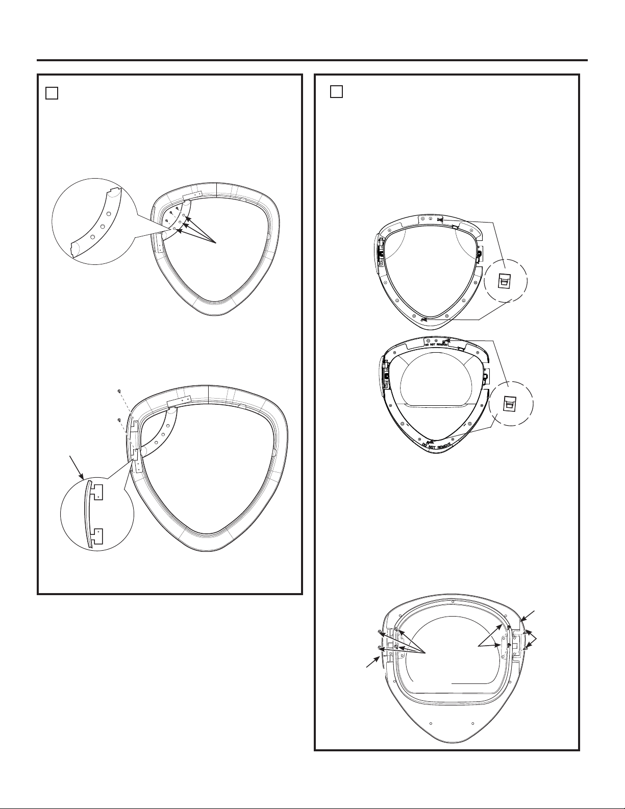
Instructions d’installation
COMMENT INVERSER LA POIGNÉE ET
LES COUVERCLES DE LA PORTE (SUITE)
Déposez le couvercle en chrome sur une surface
plane, lisse et protégée.
3
F Installez le nouveau couvercle de porte du côté
droit (de l’ensemble d’inversion) à l’aide des 2 vis
(vis taraudeuses #8 x 0,625 po).
COMMENT INVERSER LA CHARNIÈRE
ET LES COUVERCLES
• Posez la porte intérieure face vers le bas sur une
surface plate protégér, douce pour que la partie
intérieure soit tournée vers le bas.
Démontez le hublot en ouvrant 2 fermoirs, posez
le hublot sur une surface plate protégée, douce.
• Démontez le couvercle intérieur (cache) en
ouvrant 2 fermoirs, posez le couvercle intérieur
(cache) sur une surface plate protégée, douce.
4
E Réinstallez la poignée interne sur la poignée
externe à l’aide des 3 vis (vis taraudeuses #8 x
0,625 po).
Couvercle de porte
2 x D Vis
3 x D Vis
(Poignée
interne)
Poignée
extérieure
89
• Tournez la porte intérieure sur une surface plate
protégée, douce pour que la partie intérieure
soit tournée vers le haut.
• Déposez les vis, écrous et rondelles du côté
opposé de la charnière, avec un tournevis
quadrex.
• Démontez le couvercle de la porte intérieure de
la contre-porte en retirant 2 vis (vis taraudeuses
#8 x 0,75 po).
• Démontez la charnière de la porte interne en
retirant 4 vis (vis taraud #8-32 x 0,50 po).
Hublot
Couvercle
intérieur (cache)
Fermoir
Fermoir
Retirez
4 x E vis
2 vis,
2 écrous
et 2
rondelles
Charnière
2 x D Vis
Couvercle
de porte
intérieure
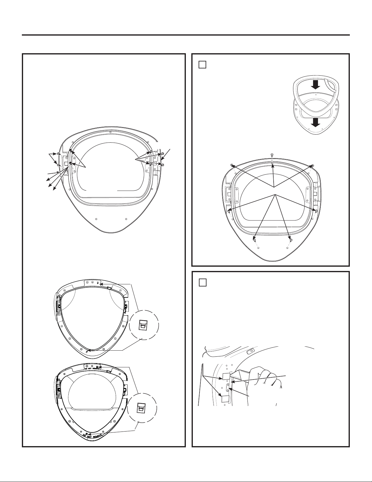
Instructions d’installation
INVERSION DE L’OUVERTURE DE LA PORTE (optionnel) (suite)
90
• Installez la charnière sur le côté opposé de la contre-
porte à l’aide de 4 vis (vis taraudeuses #8 x 0,50 po).
• Installez le nouveau couvercle de la porte intérieure
(de l’ensemble d’inversion) sur le côté opposé de la
charnière à l’aide de 2 vis (vis taraudeuses #8 x 0,75 po).
• Installez les vis, écrous et rondelles du côté opposé de la
charnière dans les 2 trous restants.
• Retournez la porte intérieure pour que la pièce intérieure
soit tournée vers le bas. Assemblez le couvercle intérieur
(cache), assurez-vous que les fermoirs ont pincé le
couvercle intérieur. Assemblez le hublot, assurez-vous
que les 2 fermoirs ont pincé le hublot.
Replacez2
x D vis
Replacez
4 x E vis
Couvercle
de porte
intérieure
Charnière
Remettez en
place 2 vis,
2 écrous et
2 rondelles
Hublot
Couvercle
intérieur
(cache)
Fermoir
Fermoir
COMMENT RÉINSTALLER LA PORTE
Retournez la contre-porte et
placez-la sur une surface lisse,
plane et protégée de sorte que la
partie intérieure soit placée vers
le bas. Assemblez le couvercle
en chrome sur la contre-porte
en les plaçant l’un contre l’autre.
Inversez la porte et procédez à
son assemblage en utilisant 7
vis (vis taraudeuses #10 x 1,125
po).
5
7 x A vis
COMMENT INVERSER LES CAPUCHONS
ET LA GÂCHE DU PANNEAU AVANT
Retirez les 2 capuchons du panneau avant de la
sécheuse, à l’aide d’un couteau à mastic ou de tout
autre outil plat comme illustré, et réinstallez-les sur
le côté opposé. Pivotez la gâche et son couvercle en
retirant 2 vis (vis taraudeuses #8 x 0,625 po) et en
les réinstallant sur le côté opposé.
6
REMARQUE: Posez un morceau de ruban gommé
sur le côté du capuchon sous lequel la lame du
couteau à mastic sera introduite afin d’éviter les
rayures.
Support
de la gâche
2 Capuchons
Morceau de
ruban gommé
REVERSE HINGE AND CAPS (CONT.)
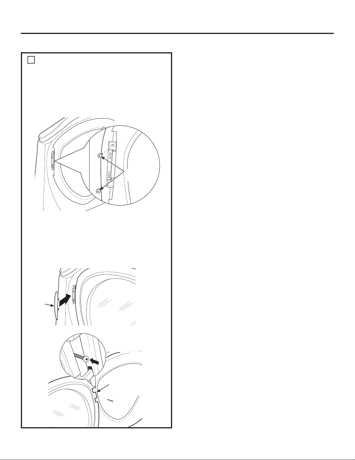
COMMENT RÉINSTALLER LA PORTE
Placez la porte sur le panneau avant de la sécheuse,
en vous assurant que le loquet est engagé et que la
charnière repose dans les deux orifices de l’avant
de la sécheuse. Installez la porte sur la carrosserie
avant à l’aide des 2 vis (vis taraudeuses #10 x 0,75
po).
Installez 2 x
B les vis
7
Installez le nouveau couvre-charnière de gauche
(de l’ensemble d’inversion) sur la charnière, en
ouvrant la porte de la sécheuse et en vissant le
couvre-charnière.
REMARQUE: Conservez les capuchons restants si
vous souhaitez inverser la charnière à nouveau.
1 x C Vis pour
couvre-charnière
Couvre-
charnière
Instructions d’installation
91
INVERSION DE L’OUVERTURE DE LA PORTE (optionnel) (suite)
COMMENT SUPERPOSER LA SÉCHEUSE À LA LAVEUSE (optionnel)
Instructions d’installation
92
AVANT DE COMMENCER
Lisez ces instructions entièrement et
soigneusement.
•
IMPORTANT – Conservez ces
instructions pour l’inspecteur local.
•
IMPORTANT – Observez tous les codes
et les ordonnances en vigueur.
• Note à l’installateur – Assurez-vous de laisser
ces instructions au consommateur.
• Note au consommateur – Conservez ces
instructions à titre de référence.
•
L’installation de la sécheuse doit être effectuée
par un installateur qualifié.
• L’installateur est responsable de bien installer cet
appareil.
POUR VOTRE SÉCURITÉ:
AVERTISSEMENT
• Risque de décharge électrique. Coupez
l’alimentation électrique avant de procéder
à l’installation. Vous risquez de vous blesser
gravement si vous ne le faites pas.
• Blessure corporelle potentielle. La sécheuse
doit être soulevée par deux personnes en raison
de son poids et de sa taille. Vous risquez de vous
blesser gravement, voire mortellement si vous
ne tenez pas compte de cette recommandation.
• Évitez le basculement et le débranchement
des services publics. La sécheuse doit être
correctement fixée à la laveuse. NE placez PAS la
laveuse au dessus de la sécheuse. Vous risquez
de vous blesser gravement, voire mortellement
ou des dommages matériels si vous ne tenez pas
compte de cette recommandation.
• Maison mobile ou préfabriquée Installation –
La superposition d’une sécheuse au gaz dans
une maison mobile ou préfabriquée n’est pas
autorisée.
DÉGAGEMENTS MINIMUMS AUTRES QUE
POUR UNE INSTALLATION ENCASTRÉE
Les dégagements minimums par rapport aux
surfaces inflammables et pour l’orifice d’aération
sont les suivants : 0 po des deux côtés, 25 mm (1 po)
à l’avant et 75 mm (3 po) à l’arrière. Veillez à prévoir
des dégagements suffisants pour toute installation
et réparation.
EXIGENCES RELATIVES À UNE
INSTALLATION ENCASTRÉE
• Votre sécheuse a été conçue pour être installée
dans une alcôve ou un placard, comme l’indique
une étiquette figurant sur l’arrière de la sécheuse.
•
L’air de la sécheuse DOIT être évacué vers
l’extérieur. Se reporter au chapitre ÉVACUATION
DE LA SÉCHEUSE.
•
L’espace minimum entre la carrosserie de la
sécheuse et les murs adjacents ou d’autres
surfaces :
0 mm (0 po) des deux côtés
75 mm (3 po) avant et arrière
•
Distance verticale minimum du sol aux étagères
suspendues, armoires, plafonds, etc. de 132 cm
(52 po).
•
Les portes du placard doivent être perforées ou
bien ventilées et disposer d’au moins 150 cm
2
(60
pouces carrés) d’espace ouvert réparti de façon
homogène. Si le placard abrite une laveuse et
une sécheuse, les portes doivent disposer de 3 m
2
(120 pouces carrés) au minimum d’espace ouvert
réparti de façon homogène.
•
L’air du placard doit être évacué vers l’extérieur
afin d’éviter la formation de poches de gaz si le
tuyau d’alimentation de gaz transporte du gaz.
•
Aucun autre appareil à combustible ne doit être
installé dans le même placard que la sécheuse
(modèles fonctionnant au gaz uniquement).
REMARQUE: SI LE TUYAU D’ÉVACUATION EST SITUÉ
À L’ARRIÈRE DE LA SÉCHEUSE, L’ESPACE MINIMUM
PAR RAPPORT AU MUR EST DE 14 cm (5,5 POUCES).
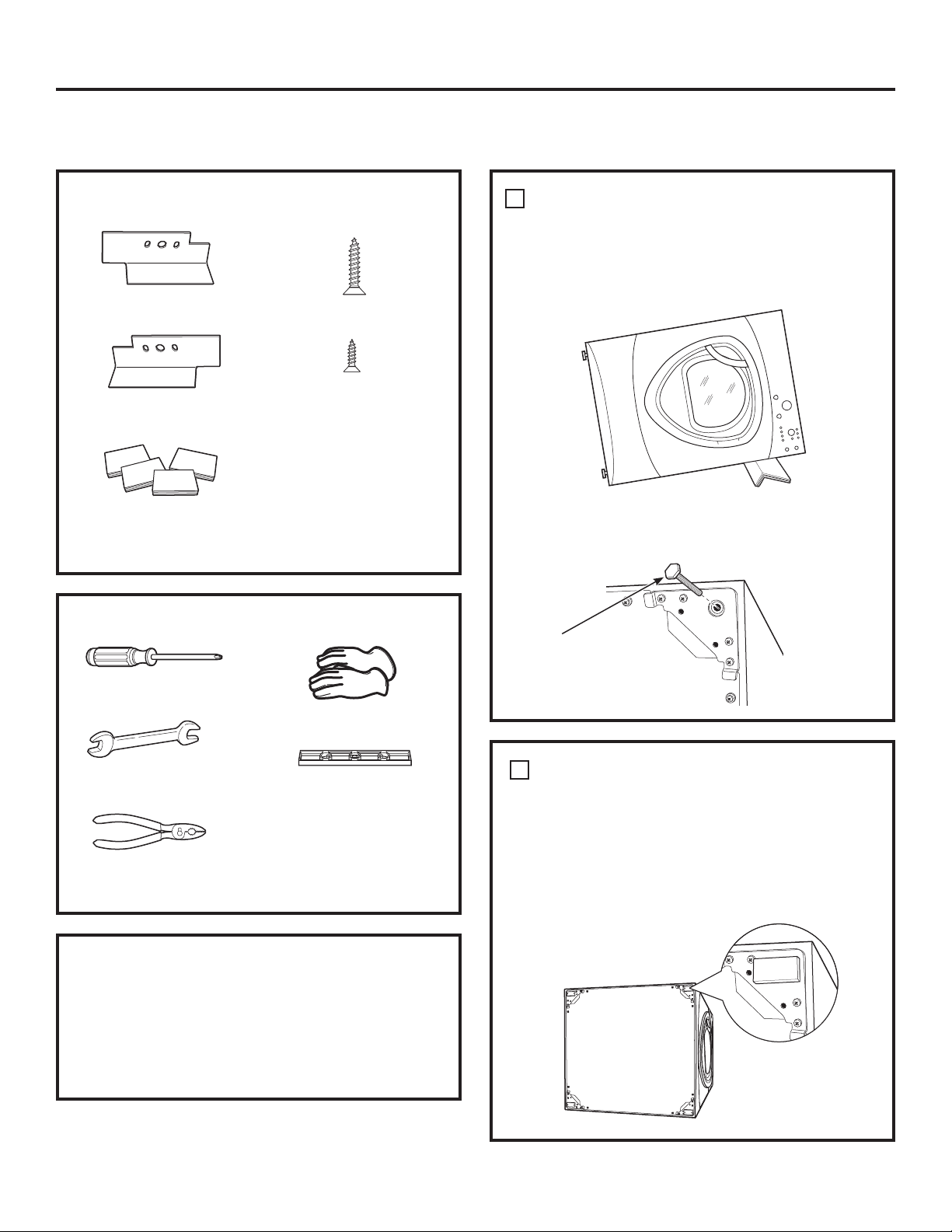
COMMENT SUPERPOSER LA SÉCHEUSE
À LA LAVEUSE (optionnel)
(suite)
COMMENT PRÉPARER L’INSTALLATION
Retirez l’emballage.
Aplatissez le carton pour l’utiliser comme cale pour
coucher la sécheuse sur le côté. Utilisez le carton
pour protéger également le sol en face de l’endroit
choisi pour l’installation.
CONTENU DE L’ENSEMBLE GE FL STACK
Support droit
Support gauche
4 cales en
caoutchouc
4 vis #12 x 1 po
4 vis #8 x 1/2 po
OUTILS NÉCESSAIRES
Tournevis cruciforme
Clé à fourche
Pince
Gants
Niveau
COMMENT INSTALLER L’ENSEMBLE DE
SUPPORT DE SUPERPOSITION
COMMENT RETIRER LES PIEDS DE
NIVELLEMENT DE LA SÉCHEUSE
A. Posez avec précaution la sécheuse sur le côté.
Utilisez le matériau d’emballage de manière à
ne pas égratigner le fini de la sécheuse.
1
B. Utilisez une clé à fourche ou une pince pour
retirer les pieds de la sécheuse.
Faites sortir et retirez les
4 pieds
COMMENT INSTALLER LES CALES EN
CAOUTCHOUC SUR LA BASE DE LA
SÉCHEUSE
Saisissez-vous des 4 cales en caoutchouc situées
dans le paquet contenant toutes les pièces. Retirez
la pellicule protectrice et collez les cales dans les
coins où vous avez retiré les pieds de nivellement.
2
Instructions d’installation
93
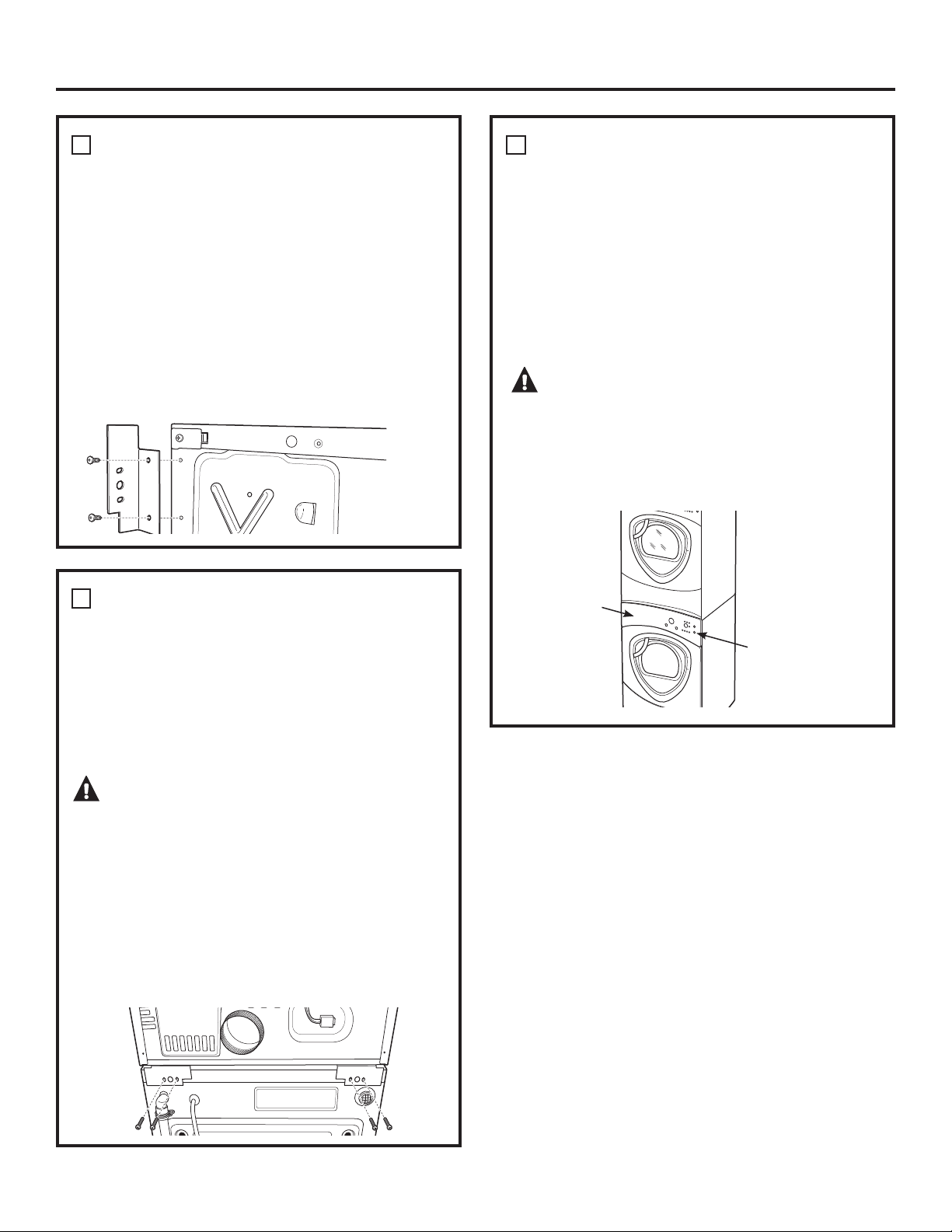
Instructions d’installation
94
COMMENT INSTALLER LE SUPPORT
SUR LA SÉCHEUSE
A. Alignez les trous du support gauche sur ceux
situés dans le coin inférieur gauche de l’appareil.
Utilisez un tournevis cruciforme pour installer les 2
vis taraudeuses #12 x 1 po.
B. Répétez l’étape ci-dessus avec le support droit
sur le coin inférieur droit de la sécheuse.
C. Remettez la sécheuse debout.
REMARQUE: Veillez à placer la sécheuse sur une
partie de l’emballage de sorte que les supports fixés
au bas de la sécheuse n’endommagent pas le sol.
3
COMMENT INSTALLER LA SÉCHEUSE
ET LE SUPPORT SUR LA LAVEUSE
A. Placez la sécheuse au-dessus de la laveuse.
Prenez soin de ne pas égratigner le dessus
de la laveuse avec les supports. Protégez le
panneau de contrôle avec du carton ou tout autre
protection. Prenez soin de soulever la sécheuse
à une hauteur suffisante de manière à ne pas
masquer le panneau de contrôle de la laveuse.
AVERTISSEMENT – Blessure
corporelle potentielle. Deux personnes sont
nécessaires pour soulever la sécheuse en raison de
son poids et de sa taille. Vous risquez de vous blesser
gravement, voire mortellement si vous ne tenez pas
compte de cette recommandation.
B. Alignez les trous du support sur ceux situés à
l’arrière de la laveuse. À l’aide d’un tournevis
cruciforme, vissez les 2 vis taraudeuses #8 x 1/2
po. Répétez l’opération pour les deux côtés de la
laveuse.
4
COMMENT TERMINER L’INSTALLATION
A. Reportez-vous aux consignes d’installation pour
terminer l’installation de la laveuse.
B. Reportez-vous aux consignes d’installation pour
terminer l’installation de la sécheuse.
C. Poussez avec précaution la laveuse et la
sécheuse superposées à leur emplacement
définitif. Utilisez des cales en feutre ou tout autre
dispositif coulissant pour faciliter le déplacement
et protéger le revêtement du sol.
AVERTISSEMENT – Blessure
corporelle potentielle. Ne poussez pas sur la
sécheuse lorsqu’elle est installée au-dessus de la
laveuse. Si vous poussez sur la sécheuse, vous
risquez de vous coincer vos doigts.
5
Placez
vos
mains ici
Placez
vos
mains ici
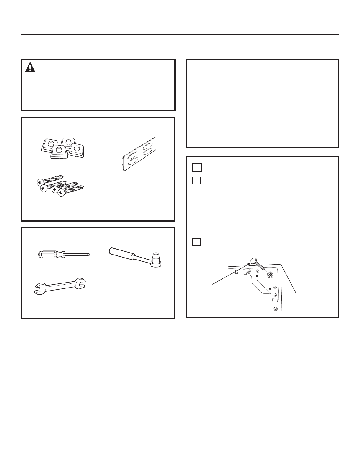
1
COMMENT RETIRER LES PIEDS
A
Déposez avec précaution la laveuse ou la
sécheuse sur le côté pour accéder aux pieds
situés au bas de l’appareil.
IMPORTANT: Ne déposez pas la sécheuse ou la
laveuse sur sa partie arrière ! Ne retirez pas les
boulons de transport situés à l’arrière de la laveuse.
Les boulons doivent rester en place jusqu’à ce que
la laveuse soit remise debout.
B
Utilisez une clé à fourche pour retirer les pieds
de la laveuse ou de la sécheuse.
COMMENT PRÉPARER L’INSTALLATION
Retirez l’emballage.
La cloison du tiroir est collée à l’aide de ruban
adhésif sur le dessus du carton d’emballage. Retirez
la cloison et mettez-la de côté pour l’installation
finale.
Aplatissez le carton pour l’utiliser comme cale pour
poser la sécheuse sur le côté. Utilisez le carton pour
protéger également le sol en face de l’endroit choisi
pour l’installation.
0,6((1*$5'(³ En raison de la
taille et du poids de ces appareils et afin de réduire le
risque de blessure ou de dommage matériel,
L’INSTALLATION DOIT ÊTRE EFFECTUÉE PAR DEUX
PERSONNES.
INSTALLATION DU SOCLE (optionnel)
CONTENU D’ENSEMBLE
4 cales de support
4 vis d’assemblage
Cloison du tiroir
OUTILS NÉCESSAIRES
Tournevis cruciforme
Clé à fourche 9/16 po
ou clé à molette
Clé à douille 7 mm
Faites sortir et retirez
les 4 pieds
Instructions d’installation
95
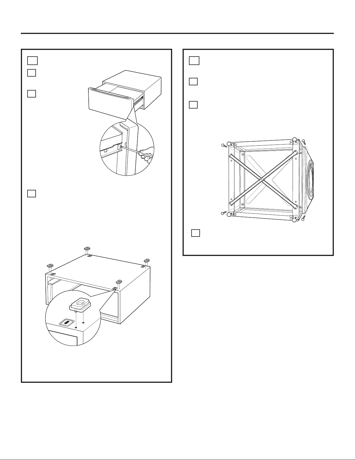
Instructions d’installation
96
3
COMMENT INSTALLER LE SOCLE SUR
LA LAVEUSE OU LA SÉCHEUSE
A
Placez le socle au bas de l’appareil. Veillez à ce
que l’avant du tiroir soit placé à l’avant de la
laveuse.
B
Alignez les trous du socle sur ceux situés au
bas de l’appareil. Utilisez un tournevis
cruciforme pour installer les 4 boulons dans le
socle et la base de l’appareil. Ne les serrez pas.
Faites glisser le socle vers l’appareil, jusqu’à ce
qu’il soit aligné de l’avant sur l’arrière. Utilisez
une clé à douille 7 mm pour serrer les boulons.
2
COMMENT PRÉPARER LE SOCLE
A
Tirez le tiroir au
maximum.
B
Retirez les vis
des glissières du
tiroir. Faites
sortir le tiroir
hors de la base
et laissez-le de
côté.
POUR LES SÉCHEUSES UNIQUEMENT:
C
Saisissez-vous des 4 cales de support dans le
paquet contenant toutes les pièces. Chaque
cale possède 2 protubérances qui s’insèrent
dans les trous situés sur le socle. Enfoncez les
cales en caoutchouc dans les trous dans
chaque coin sur le dessus du socle comme
indiqué.
REMARQUE: Les cales de support ne doivent être
installées que sur la sécheuse. N’INSTALLEZ PAS
CES CALES SUR LE SOCLE DE LA LAVEUSE.
C
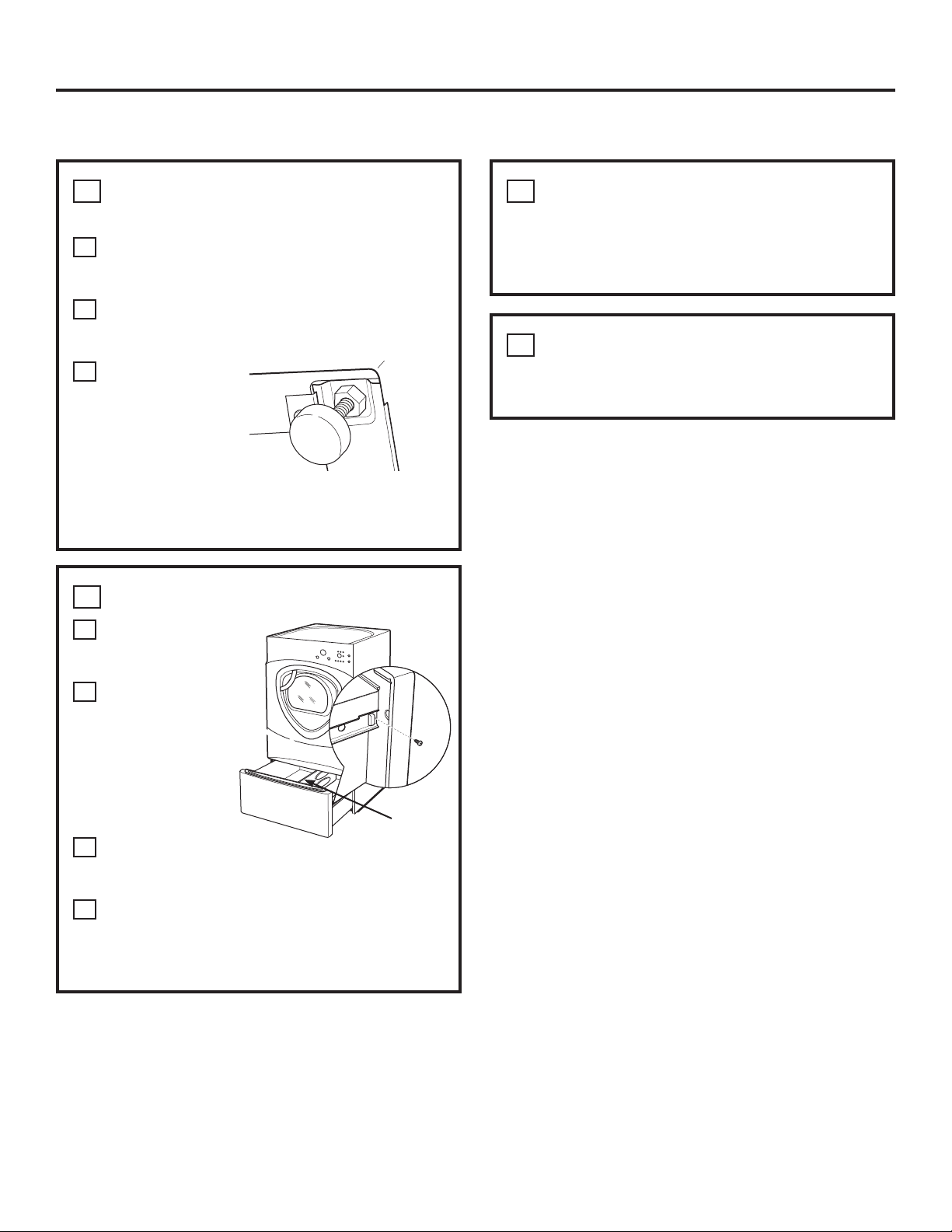
4
COMMENT METTRE LA LAVEUSE OU
LA SÉCHEUSE DE NIVEAU
A
Placez la laveuse ou la sécheuse debout.
Placez-la proximité de l’endroit où vous avez
prévu de l’installer.
B
Assurez-vous que l’appareil est de niveau en
plaçant un niveau dessus. Vérifiez le niveau de
gauche à droite, et de l’avant vers l’arrière.
C
Utilisez une clé à
fourche pour
régler les pieds.
Vissez l’écrou de
blocage au bas
du socle.
REMARQUE: Afin de réduire les vibrations, les écrous
de blocage doivent être serrés au maximum.
6
COMMENT RETIRER LES VIS DE
TRANSPORT
Retirez les 4 vis de transport situées à l’arrière de la
laveuse.
5
COMMENT
RÉINSTALLER LE TIROIR
A
Vérifiez si les
glissières sont
fermées.
B
Faites coulisser
le tiroir dans
l’ouverture.
Alignez les
supports du
tiroir sur les
glissières de
chaque côté.
C
Réinstallez les
vis dans chaque
glissière de tiroir. Serrez les deux vis.
D
Ouvrez complètement le tiroir. Faites glisser la
cloison dans les rainures situées au centre du
tiroir. Le tiroir doit coulisser en douceur
lorsque vous le poussez vers le fond.
7
COMMENT TERMINER L’INSTALLATION
Reportez-vous aux consignes d’installation de la
laveuse ou de la sécheuse pour l’installer correctement.
Cloison
Instructions d’installation
97
INSTALLATION DU SOCLE (optionnel) (suite)
98
Avant d’appeler un réparateur…
Problème Causes possibles Correctifs
La sécheuse émet Le bruit/ou les secousses sont • Placez l’appareil sur une surface plane, ou ajustez les pieds
des secousses et des bruits normaux. La sécheuse est peut-être au besoin jusqu’à ce qu’il soit bien de niveau.
placée sur une surface inégale
Le séchage est trop long Des conduits inadéquats ou bouchés • Consultez les consignes d’installation afin de vous assurer
que l’évacuation de l’air de la sécheuse est correcte.
• Veillez à ce que le conduit soit propre, non déformé et non
bouché.
• Assurez-vous que l’évent mural extérieur fonctionne sans
problème.
Tri erroné • Séparez les articles lourds des légers (en général un linge correctement
trié dans la laveuse l’est aussi dans la sécheuse).
Charges de tissus lourds • Les tissus lourds et de grande taille contiennent de l’humidité
(serviettes par exemple) et tardent davantage à sécher. Répartissez les tissus lourds
et de grande taille en de plus petites charges pour accélérer
le séchage.
Les commandes sont mal réglées • Réglez les commandes conformément à la charge que vous séchez.
Le filtre à charpie est plein • Nettoyez le filtre à charpie avant chaque utilisation.
Fusibles grillés ou disjoncteur • Remplacez les fusibles ou réenclenchez les disjoncteurs.
déclenché La plupart des sécheuse étant équipées de 2 fusibles/disjoncteurs,
assurez-vous que les deux fonctionnent.
Surcharge/charges mixtes • Ne mettez pas plusieurs charges dans la sécheuse à la fois.
Charge insuffisante • Si vous ne séchez qu’un ou deux articles, ajoutez d’autres vêtements
afin d’obtenir un bon culbutage.
Le niveau de séchage DRY La brassée est composée • Lorsque vous mélangez les tissus lourds et légers,
a été sélectionné mais de vêtements lourds et légers sélectionnez MORE DRY (PLUS SEC).
le linge est toujours humide
Le système d’évacuation est bloqué • Inspectez et nettoyez-le.
Les touches de commande
Les commandes ont été accidentellement
• Appuyez sur START/PAUSE (MISE EN MARCHE/PAUSE).
ne répondent pas réglées au mode réparation
Les commandes ont été accidentellement
• Maintenez la touche LOCK (VERROUILLAGE) enfoncée pendant
réglées au mode verrouillage 3 secondes pour déverrouiller la sécheuse.
Les commandes fonctionnement mal • Réenclenchez le disjoncteur de votre domicile.
La sécheuse Le panneau de contrôle • C’est normal. Appuyez sur POWER (ALIMENTATION) pour activer
ne démarre pas est en « veille » le panneau de contrôle.
La sécheuse est débranchée • Veillez à ce que la fiche de la sécheuse soit entièrement branchée dans
la prise.
Fusible grillé/disjoncteur déclenché • Vérifiez le fusible disjoncteur et remplacez le fusible
ou réenclenchez le disjoncteur. REMARQUE: Les sécheuses électriques
utilisent deux fusibles ou disjoncteurs.
La sécheuse a été arrêtée • Si la lumière de la touche START/PAUSE (MISE EN
par inadvertance au moment MARCHE/PAUSE) clignote, la sécheuse est arrêtée.
de régler la fonction Delay Start Appuyez sur START/PAUSE (MISE EN MARCHE/PAUSE) pour lancer
(Mise en marche différée) le compte à rebours.
Aucun chiffre n’apparaît La sécheuse évalue la quantité • C’est normal. Lorsque la sécheuse détectera un faible niveau
pendant le cycle, il ne fait d’humidité du linge d’humidité dans le linge, elle affichera le temps de séchage
que s’allumer restant.
&RQVHLOVGHGpSDQQDJH³eFRQRPLVH]GXWHPSVHWGHO·DUJHQW
Consultez d’abord les tableaux ci-dessous et vous pourrez
peut-être éviter de faire appel à un réparateur.
Avant d’appeler un réparateur… www.electromenagersge.ca
Problème Causes possibles Correctifs
Le temps restant a Le temps estimé risque de • C’est normal.
diminué changer lorsqu’une charge
plus petite est en train de sécher
Impossible de procéder
L’option DRYNESS LEVEL
• C’est normal.
à une sélection et
(NIVEAU DE SÉCHAGE),
TEMP
la sécheuse émet (TEMPERATURE) ou l’OPTION
un double bip que vous tentez de sélectionner
est incompatible avec le cycle
de séchage sélectionné
La sécheuse fonctionne L’option EXTEND TUMBLE • C’est normal. Pendant un culbutage prolongé, le temps
mais 00 est le temps (CULBUTAGE PROLONGÉ) a été restant n’est pas affiché. L’option de culbutage
restant affiché sélectionnée prolongé dure environ 20 minutes.
Nettoyez le filtre Le bouton POWER (ALIMENTATION) • Appuyez sur START/PAUSE (MISE EN MARCHE/PAUSE) pour à charpie
(message) a été activé lancer un cycle de séchage et le message disparaîtra.
La sécheuse Fusible grillé/disjoncteur • Vérifiez le fusible disjoncteur et remplacez le fusible
ne chauffe pas déclenché, la sécheuse peut ou réenclenchez le disjoncteur. Votre sécheuse
tourner mais ne chauffe pas peut tourner si un fusible est grillé ou un disjoncteur
est déclenché.
L’alimentation de gaz est • Assurez-vous que le robinet d’arrêt du gaz sur
coupée la sécheuse et que le robinet principal sont ouverts.
Le réservoir de gaz propane • Faites le plein ou remplacez le réservoir. La sécheuse
est vide ou il y a eu une coupure chauffe lorsque l’alimentation en gaz est restaurée.
de gaz naturel (modèles à gaz)
Temps de séchage Type de chaleur • Le temps de séchage variera en fonction du type de
non uniformes chauffage utilisé. Si vous avez récemment remplacé votre sécheuse
électrique par un modèle à gaz propane, ou
vice-versa, le temps de séchage peut ne pas être le même.
Type de charge et conditions • La taille du linge, les types de tissus, l’humidité du linge
de séchage et la longueur et l’état du système d’évacuation auront
une influence sur le temps de séchage.
Lueur à l’arrière Éléments chauffants derrière • C’est normal. Dans certaines conditions de séchage et
du tambour le tambour d’éclairage de la pièce, la lueur des éléments peut être
visible à l’arrière du tambour.
Le linge est toujours La porte a été ouverte au milieu • Un cycle de séchage doit être sélectionné chaque fois
humide et la sécheuse du cycle. Le linge a été ensuite qu’une nouvelle brassée est placée dans l’appareil.
s’est arrêtée après retiré de la sécheuse et une nouvelle
quelques instants charge introduite sans sélectionner
un nouveau cycle
Charge petite • Si vous séchez 3 articles au plus, sélectionnez SPEED DRY (SÉCHAGE
RAPIDE) ou TIMED DRY (SÉCHAGE MINUTÉ).
Le linge est déjà sec à l’exception • Sélectionner SPEED DRY (SÉCHAGE RAPIDE) ou TIMED DRY
des cols et les ceintures (SÉCHAGE MINUTÉ) pour sécher des cols et des ceintures.
À l’avenir, lorsque vous séchez des articles possédant
des cols et des ceintures, sélectionnez plutôt MORE DRY (PLUS SEC).
La sécheuse n’est pas placée • Placez l’appareil sur une surface plane, ou ajustez les pieds
sur une surface plane au besoin jusqu’à ce qu’il soit bien de niveau.
Le linge est froissé Séchage excessif • Sélectionnez un temps de séchage plus court.
• Retirez du linge pendant qu’il est encore légèrement humide.
Sélectionnez les options LESS DRY (MOINS SEC)
ou DAMP (HUMIDE).
Linge laissé dans la sécheuse • Retirez le linge une fois le cycle terminé, pliez et suspendez-
alors que le cycle est fini le immédiatement, ou utilisez l’option EXTEND TUMBLE (CULBUTAGE
PROLONGÉ).
Surcharge • Répartissez les tissus lourds et de grande taille
en de plus petites charges.
99
Conseils de dépannage
.
Problème Causes possibles Correctifs
Le linge a rétréci Certains tissus rétréciront • Afin d’éviter tout rétrécissement, suivez les indications
naturellement au lavage. figurant sur les étiquettes des vêtements.
D’autres peuvent être lavés
• Certains vêtements doivent être étirés après le séchage
sans problème, mais rétréciront
afin qu’ils retrouvent leur forme d’origine.
dans la sécheuse
• Si vous avez peur qu’un vêtement rétrécisse, ne le lavez pas
à la machine ou ne le séchez pas dans la sécheuse.
Des tâches de gras Une utilisation inadéquate • Suivez le mode d’emploi figurant sur l’emballage
sur le linge de l’assouplissant de l’assouplissant.
Séchage de linge propre • Utilisez votre sécheuse pour ne sécher que du linge
avec du linge sale propre. Le linge sale risque de tacher le linge propre
et la sécheuse.
Le linge n’était pas • Il arrive parfois que des taches ne soient pas visibles
complètement propre lorsque le linge est humide et apparaissent après
le séchage. Utilisez des procédures de lavage adéquates avant
le séchage.
De la charpie sur le linge Le filtre à charpie est plein • Nettoyez le filtre à charpie avant chaque utilisation.
Tri erroné • Triez les tissus producteurs de charpie (chenille par exemple)
des tissus collecteurs de charpie (le velours côtelé par
exemple).
L’électricité statique peut attirer • Se reporter aux suggestions de la section
la charpie ÉLECTRICITÉ STATIQUE.
Surcharge • Répartissez les tissus lourds et de grande taille en de plus
petites charges.
Papier, mouchoir, etc., oubliés • Videz toutes les poches avant de laver le linge.
dans les poches
Électricité statique Aucun assouplissant n’a été utilisé • Essayez un assouplissant.
• Les feuilles d’assouplissant textile de marque Bounce
MD
ont été approuvées pour toutes les sécheuses GE lorsqu’elles
sont utilisées conformément aux instructions
du fabricant.
Séchage excessif • Essayez un assouplissant.
• Réglez l’option LESS DRY (MOINS SEC)
ou DAMP (HUMIDE).
Les synthétiques, les mélanges • Essayez un assouplissant.
et les infroissables peuvent
provoquer de l’électricité statique
Les cols et les ceintures Le capteur d’humidité • Sélectionnez SPEED DRY (SÉCHAGE RAPIDE)
sont toujours humides détecte que la majeure partie ou TIMED DRY (SÉCHAGE MINUTÉ) pour sécher
à la fin du cycle du linge est sèche les cols et les ceintures humides. À l’avenir, lorsque vous
séchez des articles possédant des cols et des ceintures,
sélectionnez plutôt MORE DRY (PLUS SEC).
Légère variation C’est normal • En raison des propriétés métalliques de la peinture utilisée
de la couleur métallique pour ce produit, de légères variations de couleur peuvent se
produire en raison des conditions d’éclairage et
des angles d’observation.
100
Avant d’appeler un réparateur…
101
Avant d’appeler un réparateur… www.electromenagersge.ca
Problème Causes possibles Correctifs
La porte est trop La vapeur se condense • C’est normal.
embuée pour apercevoir sur la porte intérieure
les vêtements durant
un cycle vapeur
L’eau visible à l’intérieur La vapeur se condense • C’est normal.
de la porte et sur le haut sur ces surfaces
du filtre à charpie lors
de l’ouverture de la porte
après un cycle vapeur
De petites zones sont La vapeur se condense • Sélectionnez un cycle plus court.
humides sur les vêtements sur le tambour intérieur
après un cycle vapeur
Le cycle ou la durée du cycle • Réduire manuellement la durée du cycle pour ledit cycle.
sélectionné est trop long pour
la grosseur de la brassée
De petites quantités Une mauvaise grosseur • Sélectionnez un cycle plus court. Réduisez manuellement
d’eau sont retrouvées de brassée pour le cycle vapeur la durée du cycle pour ledit cycle.
sur le plancher, devant a été sélectionnée, un excès
la sécheuse de vapeur se condense
à l’intérieur du cabinet et fuit
De l’eau sur le plancher, Une connexion du tuyau d’eau • Resserrez la connexion.
derrière la sécheuse à la valve n’est pas assez serrée
Une rondelle de caoutchouc • Installez la rondelle de caoutchouc fournie avec le boyau.
du boyau est manquante sur
la connexion avec la valve
La sécheuse émet des La valve d’eau est ouverte, • C’est normal.
bruits d’eau remplissant le générateur
de vapeur
Le générateur de vapeur émet • C’est normal.
de la vapeur dans le tambour
De l’eau dégouline de La vapeur se condense • C’est normal.
la porte lorsque cette sur la porte intérieure
dernière est ouverte
après un Cycle Vapeur
Ne peut voir la vapeur La vapeur est relâchée à différents • C’est normal.
au début du cycle moments durant le cycle
Impossible de voir de Le bec vapeur peut être bouché • Appelez 800.GE.CARES pour commander le nécessaire de
la vapeur n’importe de débris de l’arrivée d’eau. rechange de bec WE25M71 ou pour demander
quand pendant le cycle à un technicien de le remplacer pour vous
Les vêtements sont Trop de vêtements • Insérez moins de vêtements ; augmentez manuellement
encore froissés après la durée du cycle.
un cycle vapeur
La sécheuse continue Extend Tumble a été sélectionnée • Assurez-vous que l’option Extend Tumble n’est pas
le culbutage après sélectionnée.
l’affichage qui dit
Complete (Terminer)
Les frais de déplacements à votre maison pour vous
apprendre à utiliser votre produit.
Une mauvaise installation, livraison ou entretien.
Une panne du produit si celui-ci est maltraité, mal utilisé ou
utilisé à des fins autres que celles auxquelles il est destiné,
ou utilisé commercialement.
Remplacement de l’ampoule lumineuse après sa durée
de vie utile prévue.
Le remplacement de fusibles de la maison ou le
réenclenchement des disjoncteurs.
Des dommages au produit causés par un accident, un
incendie, une inondation ou une catastrophe naturelle.
Tout dommage indirect ou consécutif causé par des pannes
possibles de cet appareil électroménager.
Des dommages après la livraison.
Le service s’il est impossible d’avoir accès au produit pour
l’effectuer.
Défauts ou dommages causés par l’utilisation aux
températures en-dessous de zéro C.
Produits qui ne sont pas défectueux ou endommagés ou qui
fonctionnent tel que décrit dans le manuel de l’utilisateur.
Ce qui n’est pas couvert (au les États-Unis):
Cette garantie est offerte à l’acheteur initial et à tout propriétaire subséquent d’un produit acheté aux États-Unis
à des fins d’usage domestique. Si le produit est situé dans une localité où un réparateur autorisé GE n’est pas
disponible, vous pourriez encourir des frais de déplacement ou devoir acheminer le produit à un réparateur autorisé
GE pour faire réparer l’appareil. En Alaska, cette garantie exclut les frais d’expédition et les visites de service à votre
domicile.
Certains États ou provinces ne permettent pas l’exclusion ou la restriction des dommages accessoires ou indirects.
Certains droits particuliers vous sont dévolus en vertu de la présente garantie et peuvent s’accompagner d’autres
droits qui varient selon votre lieu de résidence. Pour connaître la nature exacte de vos droits, consultez l’organisme
de protection du consommateur de votre région, ou encore le bureau du procureur général de l’État.
Garant: General Electric Company. Louisville, KY 40225
Tout le service sous garantie est fourni par nos Centres de
service ou par un technicien autorisé. Pour le service, appelez le
1.800.561.3344.
Veuillez fournir le numéro de série et le numéro de modèle
lorsque vous appelez pour obtenir le service.
Attachez votre reçu ici. Une
preuve de la date d’achat
d’origine est nécessaire pour
obtenir le service sous garantie.
Garantie de la sécheuse GE. (Pour des clients au les États-Unis)
(;&/86,21'(*$5$17,(6,03/,&,7(6³9RWUHVHXOHWXQLTXHUHFRXUVHVWODUpSDUDWLRQGXSURGXLWVHORQ
les dispositions de cette Garantie limitée. Toutes les garanties implicites, incluant les garanties de qualité
marchande et de convenance, sont limitées à une année ou à la période la plus courte autorisée par la
législation.
Pour une période de: Nous remplacerons:
Un an Toute pièce de la sécheuse qui se révèle défectueuse en raison d’un vice de matériaux
À partir de la date d’achat ou de fabrication. Pendant cette garantie limitée d’un an, GE prendra en charge également,
d’origine gratuitement, tous les frais de main-d’oeuvre et les frais connexes de service pour remplacer
la pièce défectueuse.
Deuxième année Toute pièce de la sécheuse qui se révèle défectueuse en raison d’un vice de matériaux
À partir de la date d’achat ou de fabrication. Pendant cette garantie limitée supplémentaire d’un an, les frais de service
d’origine ou de main-d’oeuvre correspondants seront à votre charge.
Deux à cinq ans Le tambour extra ou super de la sécheuse et le circuit électronique principal si l’une de ces
À partir de la date d’achat pièces tombe en panne à cause d’un vice de matériaux ou de main-d’oeuvre. Pendant cette
d’origine garantie limitée supplémentaire de quatre ans, les frais de service ou de main-d’oeuvre
correspondants seront à votre charge.
102
103
Garantie de la sécheuse GE. (Pour des clients au Canada)
Tout le service sous garantie est fourni par nos Centres de service ou par un technicien autorisé. Pour le
service, appelez le 1.800.561.3344.
Veuillez fournir le numéro de série et le numéro de modèle lorsque vous appelez pour obtenir le service.
Les frais de déplacements à votre maison pour vous
apprendre à utiliser votre produit.
Une mauvaise installation, livraison ou entretien.
Une panne du produit si celui-ci est maltraité, mal utilisé ou
utilisé à des fins autres que celles auxquelles il est destiné, ou
utilisé commercialement.
Remplacement de l’ampoule lumineuse après sa durée de vie
utile prévue.
Le remplacement de fusibles de la maison ou le
réenclenchement des disjoncteurs.
Des dommages au produit causés par un accident, un
incendie, une inondation ou une catastrophe naturelle.
Tout dommage indirect ou consécutif causé par des pannes
possibles de cet appareil électroménager.
Des dommages après la livraison.
Le service s’il est impossible d’avoir accès au produit pour
l’effectuer.
Défauts ou dommages causés par l’utilisation aux
températures en-dessous de zéro C.
Produits qui ne sont pas défectueux ou endommagés ou qui
fonctionnent tel que décrit dans le manuel de l’utilisateur.
Ce qui n’est pas couvert:
Garant : MABE CANADA INC.
LE GARANT N’EST PAS RESPONSABLE DES DOMMAGES INDIRECTS.
Pour une période de: Nous remplacerons:
Un an Toute pièce de la sécheuse qui se révèle défectueuse en raison d’un vice de matériaux ou
À partir de la date de fabrication. Pendant cette garantie limitée de un an, GE prendra en charge également,
d’achat d’origine gratuitement, tous les frais de main-d’œuvre et les frais connexes de service pour remplacer
la pièce défectueuse.
Deuxième année Toute pièce de la sécheuse qui se révèle défectueuse en raison d’un vice de matériaux ou
À partir de la date de fabrication. Pendant cette garantie limitée supplémentaire d’un an, les frais de service ou
d’achat d’origine de main-d’œuvre correspondants seront à votre charge.
Deux à cinq ans Le tambour extra ou super de la sécheuse et le circuit électronique principal si l’une de
À partir de la date ces pièces tombe en panne à cause d’un vice de matériaux ou de main-d’œuvre. Pendant cette
d’achat d’origine garantie limitée supplémentaire de quatre ans, les frais de service ou de main-d’œuvre
correspondants seront à votre charge.
Cette garantie est offerte à l’acheteur original et à tout autre propriétaire suivant pour les produits achetés au
Canada pour une utilisation domestique au Canada. Le service à domicile en vertu de la garantie sera fourni dans
les régions où il est disponible et où Mabe estime raisonnable de le fournir.
EXCLUSION DE GARANTIES IMPLICITES – Votre seul et unique recours est la réparation du produit selon
les dispositions de cette Garantie limitée. Toutes les garanties implicites, incluant les garanties de qualité
marchande et de convenance, sont limitées à une année ou à la période la plus courte autorisée par la
législation.
Soutien au consommateur.
Pièces et accessoires
Aux É.-U. : GEApplianceparts.com
Les personnes ayant les compétences requises pour réparer elles-mêmes leurs appareils peuvent recevoir directement
à la maison des pièces ou accessoires (les cartes VISA, MasterCard et Discover sont acceptées). Commandez en ligne
dès aujourd’hui, 24 heures sur 24 tous les jours, ou en téléphonant au 800.626.2002 durant les heures normales de
bureau.
Les instructions contenues dans le présent manuel comportent des procédures que tout utilisateur peut effectuer.
Les autres types de réparation doivent généralement être confiés à un technicien qualifié. Usez de prudence: une
réparation ou un entretien mal effectués peuvent rendre l’utilisation de l’appareil dangereuse.
Les consommateurs au Canada doivent consulter les pages jaunes pour connaître le centre de service Mabe le plus
proche, ou composer le 1.800.661.1616.
Site Web appareils électroménagers GE Aux É.-U.: GEAppliances.com
Vous avez une question ou vous avez besoin d’aide pour votre appareil électroménager? Visitez notre site Web
consacré aux appareils électroménagers GE, et ce 24 heures par jour, tous les jours de l’année! Pour des raisons de
commodité et pour accélérer le service, vous pouvez maintenant télécharger les manuels du propriétaire, commander
des pièces et même programmer les visites de service en ligne.
Au Canada: www.GEAppliances.ca
Service de réparation Aux É.-U. : GEAppliances.com
Un service de réparation expert GE se trouve à quelques pas de chez vous. Visitez notre site et programmez, à votre
convenance, une visite de service à n’importe quel jour de l’année! Ou composez le 800.GE.CARES (800.432.2737)
durant les heures normales de bureau.
Au Canada, composez le 1.800.561.3344
Studio de conception universel Aux É.-U. : GEAppliances.com
*(DSSXLHOHFRQFHSWGHGHVLJQXQLYHUVHO³GHVSURGXLWVGHVVHUYLFHVHWGHVHQYLURQQHPHQWVTXLSHXYHQWrWUHXWLOLVpV
par des personnes de tous âges, tailles et capacités. Nous reconnaissons le besoin de concevoir des produits pour un
vaste éventail d’aptitudes et déficiences mentales et physiques. Visitez notre site Web aujourd’hui pour obtenir plus de
renseignements sur l’application du design universel par GE, y compris des conceptions de cuisine pour les personnes
handicapées. Dans le cas de personnes malentendantes, veuillez composer le 800.TDD.GEAC (800.833.4322).
Au Canada, contactez : Manager, Consumer Relations, Mabe Canada Inc.
Suite 310, 1 Factory Lane
Moncton, N.B. E1C 9M3
Prolongation de garantie Aux É.-U. : GEAppliances.com
Achetez un contrat d’entretien GE et informez-vous des rabais spéciaux en vigueur pendant toute la durée de
votre garantie. Vous pouvez vous le procurer en ligne ou en composant le 800.GE.CARES (800.432.2737) durant les
heures normales de bureau. Les services à domicile GE seront toujours disponibles après l’expiration de la garantie.
Au Canada, composez le 1.888.261.2133
Communiquez avec nous Aux É.-U. : GEAppliances.com
Si vous n’êtes pas satisfait du service après-vente de GE, communiquez avec nous sur notre site Web en fournissant
tous les détails et votre numéro de téléphone, ou écrivez à : General Manager, Customer Relations
GE Appliances, Appliance Park
Louisville, KY 40225
Au Canada: www.GEAppliances.ca, ou écrivez à : Director, Consumer Relations, Mabe Canada Inc.
Suite 310, 1 Factory Lane
Moncton, N.B. E1C 9M3
Enregistrez votre électroménager Aux É.-U. : GEAppliances.com
Enregistrez votre nouvel appareil en ligne au moment qui vous convient le mieux! L’enregistrement de votre
produit dans les délais prescrits permet une meilleure communication et un service rapide, selon les modalités de
votre garantie, si besoin est. Vous pouvez également envoyer par courrier la carte d’enregistrement pré-imprimée qui
se trouve dans l’emballage de votre appareil.
Au Canada: www.GEAppliances.ca
104

Instrucciones
de seguridad
.............105–107
Instrucciones de funcionamiento
Características
de la secadora ..............113, 114
Cómo usar la secadora ...........114
Controles .....................108–111
Guía de inicio rápido .............108
Opciones de ciclo ............112, 113
Aparato Inteligente ...............116
Instrucciones de instalación
Antes de comenzar ..........117, 118
Cómo apilar la lavadora
y la secadora ................143–144
Cómo conectar mangueras
de entrada ........................120
Cómo conectar
una secadora eléctrica ......124–127
Cómo conectar
una secadora a gas .........121–123
Cómo instalar el pedestal . . . 146–148
Cómo invertir la apertura
de la puerta .................136–142
Configuración final ...............135
Salida al exterior
de la secadora ...............128–134
Ubicación de la secadora . . . 118, 119
Consejos para solución
de problemas ............148–151
Soporte al consumidor
Garantía (Canadá) ............... 153
Garantía (Estados Unidos) ........ 154
Soporte al consumidor ............ 155
Escriba los números de
modelo y de serie aquí:
Modelo # _____________
Serie # _______________
Se encuentran en una etiqueta
en el frente de la secadora
detrás de la puerta.
GUARDE ESTAS INSTRUCCIONES
106
Conecte a tierra la secadora para cumplir con los
códigos y ordenanzas vigentes. Siga los detalles de
las Instrucciones de instalación.
Almacene e instale el artefacto donde no sufra
temperaturas bajo cero o condiciones climáticas
externas.
Conecte a un circuito de suministro de energía con
clasificación, protección y tamaño adecuados para
evitar una sobrecarga eléctrica.
Quite todos los elementos de empaque filosos
y elimine todos los materiales de empaque
correctamente.
Salida al exterior/Conductos
1
Las secadoras DEBEN tener una salida al exterior
para evitar que grandes cantidades de humedad y
pelusas queden dentro de la habitación.
2
Use sólo conductos de metal rígido de 4” de
diámetro dentro del gabinete de la secadora.
Utilice sólo conductos de metal rígido o flexible de 4
pulgadas de diámetro aprobados por UL para la
salida al exterior. Nunca use conductos de plástico
u otros conductos combustibles fáciles de perforar.
EL USO DE DUCTOS PLÁSTICOS U OTROS DUCTOS
DE MATERIALES COMBUSTIBLES PODRÍA CAUSAR
UN INCENDIO. LOS DUCTOS PERFORADOS PODRÍAN
CAUSAR UN INCENDIO SI COLAPSAN O SI OCURRE
ALGUNA OBSTRUCCIÓN DURANTE EL USO O
DURANTE LA INSTALACIÓN.
Para detalles completos, siga las Instrucciones de
instalación.
INFORMACIÓN IMPORTANTE DE SEGURIDAD.
LEA TODAS LAS INSTRUCCIONES ANTES DE USAR.
QUÉ HACER SI HUELE GAS:
1
No trate de encender un fósforo, cigarrillo
o accionar cualquier artefacto a gas o
eléctrico.
2
No toque ningún interruptor eléctrico, ni
utilice ningún teléfono en su edificio.
3
Evacue la habitación, edificio o área de
todos sus ocupantes.
4
Inmediatamente llame a su proveedor
de gas desde el teléfono de un vecino.
Siga cuidadosamente las instrucciones
del proveedor de gas.
5
Si no puede comunicarse con el
proveedor de gas, llame al departamento
de bomberos.
Ley sobre agua potable inocua y tratamiento de residuos tóxicos de California
Esta ley exige que el Gobernador de California publique una lista de sustancias que según el estado provoquen
cáncer, defectos congénitos u otros daños reproductivos, y exige a las empresas que adviertan a los clientes
sobre la exposición potencial a dichas sustancias.
Los artefactos de gas pueden provocar una exposición mínima a estas sustancias, a saber, benceno, monóxido
de carbono, formaldehído y hollín, generados principalmente por la combustión incompleta de gas natural o
combustibles LP.
Las secadoras bien ajustadas minimizarán la combustión incompleta. La exposición a estas sustancias puede
minimizarse aún más mediante una ventilación adecuada hacia el exterior.
INSTALACIÓN ADECUADA
Esta secadora debe instalarse de manera adecuada y ubicarse de acuerdo con las Instrucciones de
Instalación antes de comenzar el uso. Las Instrucciones de instalación están incluidas en la parte
trasera de esta manual.
No almacene o use gasolina u otros
vapores o líquidos inflamables cerca de
este o cualquier otro artefacto.
La instalación y servicio técnico deben
realizarlos un instalador calificado, una
agencia de servicio o el proveedor de gas.
Para su seguridad, debe cumplirse con la información de este manual a fin de
minimizar el riesgo de incendio o explosión, descarga eléctrica o para prevenir daños
a la propiedad, lesiones personales o la muerte.
¡ADVERTENCIA!
¡ADVERTENCIA!
SU ÁREA DE LAVADERO
Mantenga el área debajo y alrededor de sus artefactos
libre de materiales combustibles (pelusas, papel, trapos,
etc.), gasolina, químicos y otros vapores y líquidos
inflamables.
Mantenga el piso cercano a sus artefactos limpio y seco
para reducir la posibilidad de resbalarse.
Se requiere una supervisión estricta cuando cualquier
artefacto es utilizado por niños o en su cercanía. No
permita que los niños jueguen sobre, con o dentro de
este o cualquier otro artefacto.
Mantenga el área alrededor de la salida y las áreas
cercanas libres de acumulación de pelusas, polvillo y
suciedad.
Mantenga los elementos de lavado (tales como
detergentes, lejías, etc.) fuera del alcance de los niños,
preferentemente en un gabinete cerrado con llave.
Cumpla con todas las advertencias de las etiquetas
para evitar lesiones.
Nunca se suba o pare sobre la secadora.
CUANDO USE SU SECADORA
Nunca introduzca las manos dentro de la secadora
mientras el tambor esté en movimiento. Antes de
cargar, descargar o agregar ropa, espere a que el
tambor se haya detenido por completo.
Limpie el filtro de pelusa antes de cada carga para
evitar la acumulación de pelusa dentro de la secadora
o dentro de la habitación. NO HAGA FUNCIONAR LA
SECADORA SIN EL FILTRO DE PELUSAS EN SU LUGAR.
No lave o seque artículos que se hayan limpiado, lavado,
sumergido o manchado con sustancias combustibles o
explosivas (tales como cera, aceite, pintura, gasolina,
desgrasantes, solventes para limpieza en seco,
querosén, etc.). Estas sustancias emiten vapores que
pueden encenderse o explotar. No agregue estas
sustancias al agua del lavado. No utilice o coloque
estas sustancias alrededor de su lavadora o secadora
durante el funcionamiento.
No coloque elementos expuestos a aceites comestibles
dentro de su secadora. Los elementos contaminados
con aceites para cocinar pueden generar una reacción
química que podría provocar que una carga de ropa se
prenda fuego.
Cualquier artículo que se haya utilizado con solventes de
limpieza o que contenga materiales inflamables (tales
como trapos de limpieza, trapeadores, toallas utilizadas
en salones de belleza, restaurantes o peluquerías, etc.)
no deben colocarse dentro o cerca de la secadora
hasta que los solventes o materiales inflamables se
hayan eliminado. Existen muchos productos altamente
inflamables en los hogares, tales como acetona,
alcohol desnaturalizado, gasolina, querosén, algunos
limpiadores domésticos, algunos removedores de
manchas, aguarrás, ceras, removedores de cera y
productos que contienen destilados de petróleo.
El proceso de lavado puede reducir la resistencia al
fuego de las telas. Para evitarlo, siga detenidamente las
instrucciones de cuidado del fabricante de la prenda.
No seque artículos que contengan goma, plástico o
materiales similares, tales como sostenes con relleno,
zapatillas, galochas, alfombrillas de baño, alfombras,
baberos, pantalones para bebés, bolsas plásticas,
almohadas, etc. que podrían derretirse o quemarse.
Cuando se calientan, algunos materiales de goma
pueden, en algunas circunstancias, producir un incendio
por combustión espontánea.
No almacene plástico, papel o prendas que puedan
quemarse o derretirse sobre la secadora durante el
funcionamiento.
Las prendas con etiquetas como Secar alejado del
calor o No secar en secadora (como los chalecos
salvavidas que contienen Kapok) no debe colocarse en
su secadora.
No seque artículos de fibra de vidrio en la secadora.
Puede producirse irritación en la piel debido a las
partículas que se pegan a la ropa durante usos
posteriores.
Para minimizar la posibilidad de una descarga eléctrica,
desenchufe este artefacto del suministro de energía o
desconecte la secadora desde el panel de distribución
doméstico quitando los fusibles o apagado el disyuntor
antes de realizar mantenimiento o limpiar (excepto la
remoción y limpieza del filtro de pelusas).
NOTA: Presionar START/PAUSE (inicio/pausa) o POWER
(encendido) NO desconecta el artefacto del suministro
de energía.
Si ve agua sobre el piso alrededor de la secadora, llame
al servicio técnico.
No obstruya el flujo del aire ventilado. No apile, no
coloque ropa, no eche alfombras al frente o al respaldo
de la secadora.
INFORMACIÓN IMPORTANTE DE SEGURIDAD.
LEA TODAS LAS INSTRUCCIONES ANTES DE USAR. GEAppliances.com
107

108
CUANDO NO USA SU SECADORA
Tome el enchufe con firmeza cuando desconecte
este artefacto para no dañar el cable mientras tira del
mismo. Coloque el cable alejado de áreas de tránsito
para que nadie lo pise, lo dañe o se tropiece con él.
No trate de reparar o cambiar ninguna pieza de
este artefacto ni trate de efectuar arreglos a menos
que se recomiende en este Manual de usuario o
en instrucciones de reparación publicadas que
usted comprenda y cuente con las habilidades para
efectuarlas.
Antes de deshacerse de la secadora, o quitarla del
servicio, quite la puerta para evitar que los niños se
escondan en su interior.
No altere o modifique los controles.
¡ADVERTENCIA!
CUANDO USE SU SECADORA (cont.)
Nunca trate de utilizar este artefacto si está dañado,
parcialmente desarmado, funciona mal, o tiene piezas
rotas o faltantes, incluyendo un cable o enchufe
dañados.
Un técnico calificado debe limpiar la parte interna de la
máquina y la conexión del conducto de salida dentro
de la secadora por lo menos una vez al año. Ver la
sección Consejos de clasificación y carga de la página
112.
Si su secadora es a gas, ésta se encuentra equipada
con un encendido automático eléctrico y no tiene
una luz piloto. NO TRATE DE ENCENDERLA CON UN
FÓSFORO. Puede sufrir quemaduras por tener su
mano muy cerca del quemador cuando se acciona el
encendido automático.
No abra la puerta de la secadora durante ciclos de
vapor. El vapor está muy caliente y seguirá saliendo
de la boca durante varios segundos después de la
apertura. No toque la boca de vapor después del ciclo
de vapor.
No utilice el ciclo de vapor con elementos tales como
lana, cuero, seda, lencería, productos de espuma o
colchas eléctricas.
No utilice ciclos de vapor en prendas nuevas sin
lavarlas primero.
Quizás desee suavizar las telas o reducir la electricidad
estática de ellas utilizando un suavizante de telas
aplicado en la secadora o un acondicionador anti-
estática. Recomendamos que use un suavizante
de telas en el ciclo de lavado, de acuerdo con las
instrucciones del fabricante de dichos productos, o
que pruebe un producto para uso en secadoras del
cual el fabricante ofrezca una garantía escrita en el
paquete de que su producto puede usarse en forma
segura en la secadora. Los arreglos o problemas
de funcionamiento provocados por el uso de tales
productos son responsabilidad de los fabricantes de
dichos productos y no se encuentran cubiertos por la
garantía de este artefacto.
Nunca trate de utilizar los ciclos de estirar por vapor
o renovación por vapor sin prendas en el tambor.
Además, se recomienda enfáticamente seleccionar el
tamaño de carga apropiado para mejores resultados.
Seleccionar ciclos de cargas grandes para cargas
pequeñas puede mojar las ropas y seleccionar ciclos de
cargas pequeñas para cargas grandes puede generar
un desempeño pobre de estiramiento.
Nunca atomice cualquier tipo de aerosol en, sobre o
cerca de la secadora. No use ningun tipo de limpiador
aerosol al limpiar el interior de la secadora. Humos
peligrosos o choque eléctrico pueden ocurrir.
INFORMACIÓN IMPORTANTE DE SEGURIDAD.
LEA TODAS LAS INSTRUCCIONES ANTES DE USAR.
GUARDE ESTAS INSTRUCCIONES
LEA Y SIGA ESTA INFORMACIÓN DE SEGURIDAD CUIDADOSAMENTE
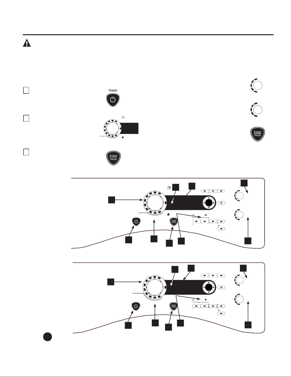
ENTER
HIGH
MEDIUM
LOW
EXTRA LOW
ANTI -
BACTERIAL
DRY
TEMP
SENSOR
DRY
MORE DRY
DRY
LESS DRY
DAMP
EXTRA DRY
P
OWER
DELAY
STAR T
Push to Lock Control
Hold 3 Secs to Unlock
e
DRY
DRYER
RACK
LOCK
BACKBACK
SPECIALTY
CYCLES
PRESS & HOLD 3 seconds for secondary OPTIONS
STORE MY CYCLE
EXTENDED
TUMBLE
DRUM
LIGHT
SETTINGS
MY
CYCLE
DAMP
ALERT
SPEED DRY
ACTIVE WEAR
WRINKLE FREE
DELICATES
NORMAL /
MIXED LOADS
COTTONS
SENSOR DRY
TIME DRY
DEWRINKLE
WARM UP
TIMED DRY
AIR FLUFF
NO HEAT
¡ADVERTENCIA! Para reducir el riesgo de incendio, descarga eléctrica o lesiones a personas, lea
las INSTRUCCIONES IMPORTANTES DE SEGURIDAD antes de utilizar este
aparato.
Sobre el panel de control de la secadora.
GEAppliances.com
A lo largo de este manual, las características y apariencia pueden ser diferentes a las de su
modelo.
Inicio rápido
Si la pantalla está oscura, presione el botón POWER (encendido)
para “despertar” la pantalla.
1
Presione el botón POWER.
2
Seleccione un ciclo girando la
perilla Cycle (ciclo).
3
Si seleccionó SENSOR CYCLE (ciclo con
sensor) sólo presione el botón START/
PAUSE (inicio/pausa).
Si seleccionó un TIMED DRY CYCLE (ciclo de
secado temporizado), elija su configuración
de calor y el tiempo de secado que prefiere
mediante los botones del cursor. Luego
presione el botón START/PAUSE.
Power (encendido)
Presione para “despertar” la pantalla. Si la pantalla está activa, presione para apagar la secadora.
NOTA: Presionar POWER no desconecta el artefacto del suministro de energía.
1
HIGH
MEDIUM
LOW
EXTRA LOW
ANTI -
BACTERIAL
DRY
TEMP
SENSOR
DRY
MORE DRY
DRY
LESS DRY
DAMP
EXTRA DRY
ENTER
HIGH
MEDIUM
LOW
EXTRA LOW
ANTI -
BACTERIAL
DRY
TEMP
SENSOR
DRY
MORE DRY
DRY
LESS DRY
DAMP
EXTRA DRY
POWER
DELAY
STAR T
Push to Lock Control
Hold 3 Secs to Unlock
e
DRY
DRYER
RACK
LOCK
BACKBACK
SPECIALTY
CYCLES
PRESS & HOLD 3 seconds for secondary OPTIONS
STORE MY CYCLE
EXTENDED
TUMBLE
DRUM
LIGHT
SETTINGS
MY
CYCLE
DAMP
ALERT
STEAMREFRESH
SPEED DRY
WARM UP
ACTIVE WEAR
WRINKLE FREE
DELICATES
NORMAL /
MIXED LOADS
SENSOR DRY
TIME DRY
TIMED DRY
STEAM
DEWRINKLE
COTTONS
1
2
3
4
5
6
7
8
9
Modelos: PFDS450 / PFDS455 / PFMS450 / PFMS455
Modelos: PFDN440 / PFDN445 / PFMN440 / PFMN445
2
3
1
4
5
6
7
8
9
S
TEAM
R
EFRESH
S
PEED
D
RY
W
ARM
U
P
A
CTIVE
W
EAR
W
RINKLE
F
REE
D
ELICATES
N
ORMAL /
M
IXED
L
OADS
SENSOR DRY
TIME DRY
C
OTTONS
SPECIALTY
CYCLES
T
IMED
D
RY
S
TEAM
D
EWRINKLE
109
110
2
Sobre el panel de control de la secadora.
Dry Cycles (ciclos de secado)
El ciclo de secado controla el tiempo del ciclo para el proceso de secado. La tabla siguiente lo ayudará a combinar la
configuración de secado con las cargas.
Sensor Cycles (ciclos con sensor)
COTTONS (algodones) Para algodones y la mayoría de los linos.
NORMAL/ Para cargas que cuentan con algodones y mezclas de poliéster.
MIXED LOAD
(carga normal/mixta)
WRINKLE FREE Para prendas libres de arrugas/cuidado sencillo y de planchado permanente.
(libre de arrugas)
ACTIVE WEAR Prendas utilizadas para ejercicio físico activo y algunas prendas informales. Las telas
(ropa deportiva) incluyen acabados de tecnología nueva y fibras elásticas como el Spandex.
DELICATES Para lencería y telas delicadas.
(delicados)
SPEED DRY Para cargas pequeñas que se necesitan cuando antes, como uniformes deportivos o
(secado rápido) escolares. También puede usarse si el ciclo anterior dejó húmedas algunas partes, como
cuellos o cinturas.
Timed Dry Cycles (ciclos de secado temporizado)
STEAM REFRESH Para prendas secas ligeramente arrugadas. Reduce significativamente las arrugas en 1–5
(renovación prendas. Seleccionar una cantidad más elevada de prendas para el ciclo (Ej., seleccionar
por vapor) una carga de 5 prendas para una carga de 1 prenda) puede dejar las ropas muy húmedas.
Después del ciclo SteamRefresh (renovación por vapor), la unidad emitirá un pitido y
mostrará “Garments Ready” (prendas listas) y “0:00”. Si la unidad no se apaga o si la puerta
no se abre, la secadora seguirá girando por 30 minutos. Al finalizar los 30 minutos, aparecerá
en la pantalla “0:00” y “Cycle Complete” (“0:00” y “ciclo completo”).
NOTA: Cuando se selecciona STEAM REFRESH (renovación por vapor), se accionará “EXTENDED
TUMBLE” (secado prolongado) en forma automática y no podrá apagarse.
En el ciclo de renovación por vapor puede hacer falta que se agregue una prenda adicional a
una prenda única de tela extremadamente liviana para lograr resultados óptimos.
DEWRINKLE Para quitar arrugas de prendas que se encuentran secas o apenas húmedas.
(quita arrugasr) No se recomienda este ciclo para telas delicadas.
STEAM DEWRINKLE Para usar con cargas más importantes que las de RENOVACIÓN POR
VAPOR. Ideal para
(estirar por vapor) cargas que se dejan en la secadora durante períodos prolongados. Seleccionar un ciclo
mayor al necesario (Ej., seleccionar una carga grande para una secadora llena por la mitad)
puede dejar las ropas excesivamente húmedas.
WARM UP Brinda 10 minutos de calentamiento de las ropas.
(calentamiento)
My Cycle (mi ciclo) (en algunos modelos)
MY CYCLE Presione para usar, crear o modificar ciclos de secado personales.
(mi ciclo)
Timed Dry (secado temporizado)
Utilícelo para configurar su propio tiempo de secado. TIMED DRY también se recomienda
para pequeñas cargas.
Para usar TIMED DRY:
1. Gire la perilla de ciclo de secado a TIMED DRY.
2. Seleccione el tiempo de secado presionando los botones y . Usted puede incrementar el tiempo en unidades
de 10 minutos hasta 2 1/2 horas.
3. Seleccione DRY TEMP (temperatura de secado).
4. Cierre la puerta.
5. Presione START/PAUSE (inicio/pausa).
Sensor Dry Level (nivel de secado con sensor)
El sensor continuamente monitorea la cantidad de humedad de la carga. Cuando la humedad de sus ropas alcanza
su nivel de secado seleccionado, la secadora se detendrá.
EXTRA DRY Para telas muy resistentes o prendas que deben estar muy secas, como las toallas.
(secado extra)
MORE DRY (más seco) Úselo para telas pesadas o de tipo mixto.
DRY (seco) Úselo para un nivel de secado normal adecuado para la mayoría de las cargas.
Este es el ciclo preferido para ahorrar energía.
LESS DRY (menos seco) Úselo para telas más livianas (ideal para planchado).
DAMP (húmedo) Para dejar las prendas parcialmente húmedas.
3
4
(en algunos modelos)
(en algunos modelos)
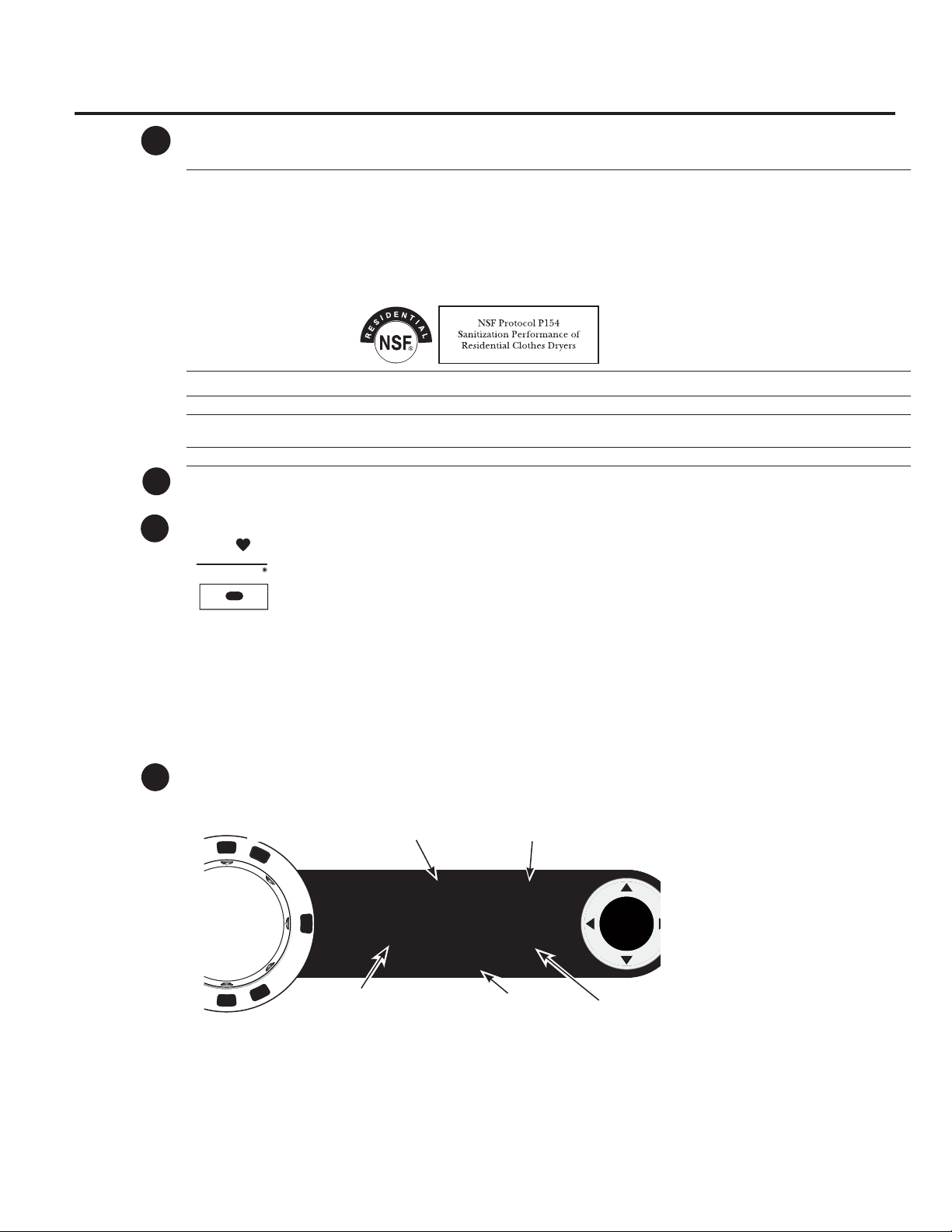
GEAppliances.com
Dry Temp (temperatura de secado)
Usted puede cambiar la temperatura de su ciclo de secado.
ANTI-BACTERIAL Esta opción sólo puede usarse con los ciclos COTTONS (algodones) o MIXED LOAD (carga
mixta). Esta opción reduce el 99,9% de ciertos tipos de bacterias, por ejemplo:
Staphylococcus aureus, Pseudomonas aeruginosa y Klebsiella pneumoniae*. El proceso
antibacterial ocurre cuando se utiliza calor elevado durante una parte del ciclo de secado.
NOTA: No use este ciclo con telas delicadas.
* El ciclo anti-bacterial esté certificado por NSF International (antes National Sanitation Foundation)
de acuerdo con el protocolo NSF P154 Sanitization Performance of Residential Clothes Dryers
(Desinfección de secadoras residenciales).
HIGH Para algodones normales a pesados.
MEDIUM Para sintéticos, mezclas y prendas marcadas como planchado permanente.
LOW Para delicados, sintéticos y prendas marcadas como Tumble Dry Low (secado bajo en
secadora).
EXTRA LOW Para lencería y telas delicadas.
START/PAUSE (inicio/pausa)
Presione para comenzar un ciclo de secado. Si la secadora está funcionando, presiónelo una vez
y la secadora se detendrá. Presiónelo de nuevo para volver al ciclo de secado.
My Cycle (mi ciclo) (en algunos modelos)
Ingrese su combinación favorita de configuraciones y guárdelas aquí para poder acceder a ellas con un
toque. Estas configuraciones personales pueden ingresarse mientras un ciclo está en funcionamiento.
Para guardar una combinación de configuraciones MY CYCLE:
1. Seleccione su ciclo de secado.
2. Cambie las configuraciones de DRY TEMP y SENSOR DRY LEVEL para ajustarse a sus necesidades.
3. Seleccione cualquier opción de secado que desee en OPTIONS.
4. Presione y sostenga el botón MY CYCLE durante tres segundos para conservar su selección. Sonará un
pitido y el botón se encenderá. Sonará un pitido, el botón se encenderá y la unidad mostrará “Mi ciclo
ahora está programado con las configuraciones de ciclo actuales”.
Para recordar su combinación conservada MY CYCLE:
Presione el botón MY CYCLE antes de secar una carga. La luz de alrededor del botón se encenderá cuando se selecciona
MY CYCLE.
Para cambiar su combinación conservada MY CYCLE:
Siga los pasos de 1–4 de “Para guardar una combinación de configuraciones MY CYCLE”.
Pantalla
“CLEAN LINT FILTER” (message) (limpiar filtro de pelusas) (mensaje)
Este mensaje se mantiene durante 15 minutos después de la finalización del ciclo.
Este mensaje aparece en forma periódica. Es sólo un recordatorio.
5
6
7
STORE MY CYCLE
M
Y
CYCLE
8
ENTER
SPECIALTY
CYCLES
SPECIALTY CYCLE 1:10
Comforters
Delay Time 1:00
Clean Lint Filter
0
Pantalla de condición
de filtro de pelusas
TIEMPO DE
RETARDO
Condición de
tiempo de retardo
Tiempo de ciclo establecido
O tiempo para secar
Condición de ciclo especial O secado
por tendedero O secado temporizado
Después de presionar el
botone POWER, el mensaje
CLEAN LINT FILTER podría
aparecer si el previo ciclo no
esté terminado. Este mensaje
desaparecerá al oprimir
el botone START. Aunque
ya limpió el filtro (antes
que el botone POWER esté
oprimido), el mensaje CLEAN
LINT FILTER estará todavía
en la pantalla hasta que el
botone START esté activado).
111

112
Sobre el panel de control de la secadora.
Specialty Cycles (ciclos especiales)
1. Gire la perilla CYCLE (ciclo) a SPECIAL CYCLES (ciclos especiales). Aparecerá en la pantalla una lista de
opciones de ciclo.
2. Mediante los botones del cursor, seleccione una categoría (CATEGORY).
3. Mediante los botones del cursor, seleccione un ciclo (CYCLE).
Presione el botón BACK (atrás) para volver a las categorías.
4. Presione ENTER (ingresar) para seleccionar.
5. Presione el botón START/PAUSE (inicio/pausa).
Los ciclos especiales (SPECIALTY CYCLES) incluyen:
Prendas
Abrigos
Jeans
Khakis
Medias/Sostenes (use una bolsa de red)
Cama y baño
Edredones
Mantas (Algodón)
Sábanas
Toallas
Otras especialidades
Algodón delicado
Bolsas de dormir
Camas de mascotas
Corderito
Dryel
Mantas de viaje
Prendas de juego
Secado con aire
Secado en bandeja
Secado por tendedero
Telas para deporte
9
Ciclos con comunicación con la lavadora
Para activar la comunicación, presione el botón
SETTINGS (configuraciones) del panel de control de la
lavadora. Cuando aparece “DRYER LINK” (conexión con
secadora) en la pantalla, presione ENTER. Utilizando
las flechas, seleccione ON (encendido) y luego presione
ENTER.
Cuando finaliza el ciclo de la lavadora, ésta se
comunicará con la secadora cuando se presione
cualquier botón del panel de control o se abra la
puerta.
La lavadora mostrará la siguiente leyenda:
“TRANSFERRING CYCLE INFORMATION TO THE DRYER”
(transfiriendo información del ciclo a la secadora) y la
secadora mostrará: “RECEIVING CYCLE INFORMATION
TO THE DRYER” (secadora recibiendo información del
ciclo).
La secadora se comunicará con la lavadora sólo si la
secadora no está operando un ciclo.
Si la lavadora comienza un nuevo ciclo antes de
que la secadora puede comunicarse con ella, la
información se perderá.
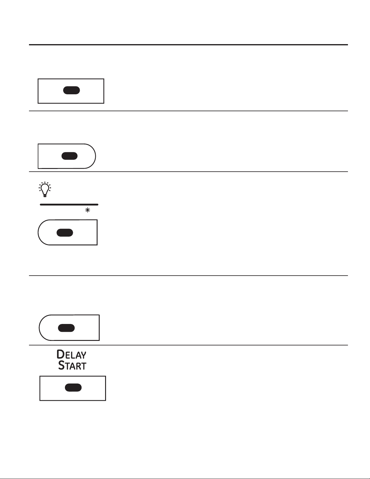
Sobre las opciones de ciclo.
NOTA: No todas las características se encuentran disponibles en todos los modelos de secadora.
GEAppliances.com
Extend Tumble (secado prolongado)
Minimiza las arrugas al agregar
aproximadamente 60 minutos de secado sin
calor después de que las prendas están secas.
La luz del centro del botón se encenderá cuando
EXTENDED TUMBLE (secado prolongado) esté
accionado.
La rotación extendida se selecciona
automáticamente para el ciclo SteamRefresh
(renovación por vapor) y no puede cancelarse
su selección. La secadora emitirá un pitido
y mostrará “Garments Ready” (prendas listas)
cuando la renovación por vapor haya finalizado.
La secadora continuará con la rotación
extendida hasta que se abra la puerta.
Damp Alert (alerta de humedad)
Esta opción hace que la secadora emita un
pitido cuando las prendas se han secado hasta
un nivel húmedo. Retire las prendas que quiere
colgar. DAMP ALERT sólo sonará cuando se
selecciona esta opción.
Quitar algunas prendas y colgarlas cuando
están húmedas puede reducir la necesidad de
plancharlas.
La luz del centro del botón se encenderá
cuando DAMP ALERT (alerta de humedad) esté
accionado.
Drum Light (luz del tambor)
Presione este botón para encender la luz de la
secadora.
Presione el botón de nuevo para apagar la luz.
Esto sólo controla la luz cuando la puerta está
cerrada. NOTA: Cuando se cierre la puerta, la
luz se apagará sola después de un minuto.
Cuando se abre la puerta, la luz se enciende
automáticamente.
La luz del centro del botón se encenderá
cuando DRUM LIGHT (luz del tambor) esté
accionado.
NOTA: Mantenga presionado el botón DRUM
LIGHT (luz del tambor) durante 3 segundos para
acceder al menú SETTINGS (configuraciones).
(Ver página 10 para más detalles).
Delay Start (inicio retardado)
Utilícelo para retardar el inicio de su secadora.
1. Elija un ciclo de secado y cualquier otra
opción.
2. Presione DELAY START. Usted puede cambiar
el tiempo de inicio retardado en unidades de
1/2 hora utilizando los botones de flecha o
.
3. Presione START/PAUSE (inicio/pausa) para
iniciar la cuenta regresiva.
El tiempo restante podrá verse en la pantalla de
ESTIMATED TIME REMAINING (tiempo restante
estimado).
NOTAS:
Si la puerta se abre mientras la secadora
se encuentra en DELAY (retardo), la cuenta
regresiva no volverá a iniciarse a menos
que la puerta esté cerrada y el botón
START/PAUSE se haya presionado de nuevo.
Se puede retardar el inicio de un ciclo de
secado hasta 24 horas.
La luz del centro del botón se encenderá cuando
DELAY START (inicio retardado) esté accionado.
e-Dry (secado ecológico)
Reduce el consumo total de energía de ciclos
específicos de la secadora mediante el ajuste
de ciertas configuraciones de calor.
NOTA: Los tiempos de los ciclos cambiarán
cuando se selecciona e-DRY.
Este ciclo puede utilizarse con DELICATES
(delicadas), ACTIVE WEAR (prendas deportivas),
EASY CARE (cuidado fácil), NORMAL/MIXED
LOADS (cargas normales/mixtas) y COTTONS
(algodones).
E
XTENDED
TUMBLE
DAMP
ALERT
DRUM
LIGHT
SETTINGS
e
DRY
113

114
Settings (configuraciones)
Bajo la opción SETTINGS, usted puede ajustar
el volumen o el brillo de la pantalla.
VOLUMEN
El volumen del final de ciclo (señal) puede
configurarse en HIGH (alto), MED (mediano),
LOW (bajo) o OFF (apagado).
El volumen de sonidos del control puede
configurarse en HIGH, MED, LOW o OFF.
DISPLAY BRIGHTNESS (brillo de la pantalla)
puede configurarse como HIGH, MED o LOW.
NOTA: Para acceder al menú SETTINGS
(configuraciones), mantenga presionado el
botón DRUM LIGHT (luz del tambor) durante
3 segundos.
Sobre las características de la secadora.
Built-In Rack Dry System (sistema de tendedero incorporado)
Un útil tendedero puede usarse para secar elementos tales como zapatillas. Coloque las
prendas en forma horizontal sobre el tendedero y bloquee prendas como suéters de lana
y telas delicadas. Seque con calor bajo.
Para instalar el Built-In Rack Dry System
1. Constate que el tambor de la secadora esté orientado de modo que el sistema de
secado de tendedero se encuentre sobre el lado izquierdo de la secadora.
2. Saque la pantalla del tendedero del lado izquierdo y trabe las “varillas” de la manija en
las ranuras opuestas del deflector.
3. Coloque la prenda sobre el tendedero y cierre la puerta.
4. Presione el botón DRYER RACK (secado por tendedero).
5. Seleccione el tiempo deseado con el botón TIME.
6. Presione el botón START/PAUSE (inicio/pausa).
NOTA:
No use este tendedero cuando haya otras prendas en la
secadora.
Asegúrese de desconectar el tendedero al finalizar el ciclo y
retraiga por completo la pantalla dentro del deflector.
Lámpara del tambor
Antes de colocar la bombilla de luz, asegúrese de desenchufar el cable de energía de
la secadora o desconectar la secadora del panel de distribución hogareño quitando
los fusibles o apagando el disyuntor. Busque por encima de la abertura de la secadora
dentro del tambor. Quite la bombilla y cámbiela por una del mismo tamaño.
Sobre las opciones de ciclo.
NOTA: No todas las características se encuentran disponibles en todos los modelos de secadora.
Enganche las varillas
Lock (bloqueo)
Se pueden bloquear los controles para evitar
que se hagan otras selecciones. O se pueden
bloquear los controles después de iniciado un
ciclo.
Cuando se selecciona esta opción, los niños no
pueden encender la secadora accidentalmente
presionando los botones.
Para bloquear la secadora, presione el botón
LOCK. Para desbloquear la secadora, presione
y sostenga el botón LOCK durante 3 segundos.
La luz del centro del botón LOCK se encenderá
cuando los controles estén bloqueados.
Aunque los controles estén bloqueados, el botón
POWER (encendido) se encuentra activo en caso
de que necesite apagar la unidad.
Presione para bloquear el control
Sostenga durante 3 segundos para desbloquear
LOCK
D
RUM
LIGHT
SETTINGS
Presione y sostenga durante
3 segundos para opciones
secundarias

Sobre las características de la secadora.
GEAppliances.com
Cómo usar el gancho
incorporado para colgar prendas
1. Constate que el tambor de la
secadora esté orientado de modo
que el gancho se encuentre sobre el
centro de la secadora.
2. Utilizando un dedo, quite el gancho
del deflector.
3. Cuelgue la prenda de una percha,
cuelgue la percha de un gancho y
cierre la puerta.
4. Presione el botón DRYER RACK
(secado por tendedero).
5. Seleccione el tiempo deseado.
6. Presione el botón START/PAUSE
(inicio/pausa).
Reverse Tumble
™
(Secado reverso)
Todas las secadoras Profile de carga frontal se encuentran equipadas con la
característica de Reverse Tumble
™
, como parte del sistema Duo Dry Plus
™
. Al invertir
la dirección de rotación del tambor durante el ciclo de secado, la secadora enredará
menos la carga de ropa, secará de forma más pareja y reducirá los tiempos de
secado. Las cargas típicas tales como ropa de cama y de baño, en las que las
sábanas, toallas y fundas de almohadas se lavan juntas, sacan provecho de esta
característica. Cuando la secadora invierte la dirección, habrá una pequeña pausa
y un cambio de sonido. Esto es normal. Todos los ciclos de la secadora utilizan esta
característica, excepto cuando se selecciona la opción de tendedero, en cuyo caso
el tambor no gira.
Cómo usar la secadora.
Siempre siga las instrucciones de la etiqueta del fabricante de la prenda cuando realice los lavados.
Consejos de clasificación y
carga
Como regla general, si las prendas están
bien clasificadas para la lavadora, estarán
bien clasificadas para la secadora.
También trate de clasificar las prendas de
acuerdo al tamaño. Por ejemplo, no seque
una sábana con medias u otros elementos
pequeños.
No agregue suavizante de telas una
vez que la carga se ha calentado. Esto
puede provocar manchas de suavizante.
El acondicionador de telas Bounce
®
en
hojas para secadoras ha sido aprobado
para su uso en esta secadora cuando se
utiliza de acuerdo con las instrucciones del
fabricante.
Ver abajo para las instrucciones de
limpieza del filtro de pelusas.
No la sobrecargue. Eso malgasta energía
y provoca arrugas.
No seque los siguientes elementos:
Productos de fibra de vidrio, prendas de
lana, productos revestidos en caucho,
plásticos, productos con ribetes plásticos
y rellenos con espuma.
115
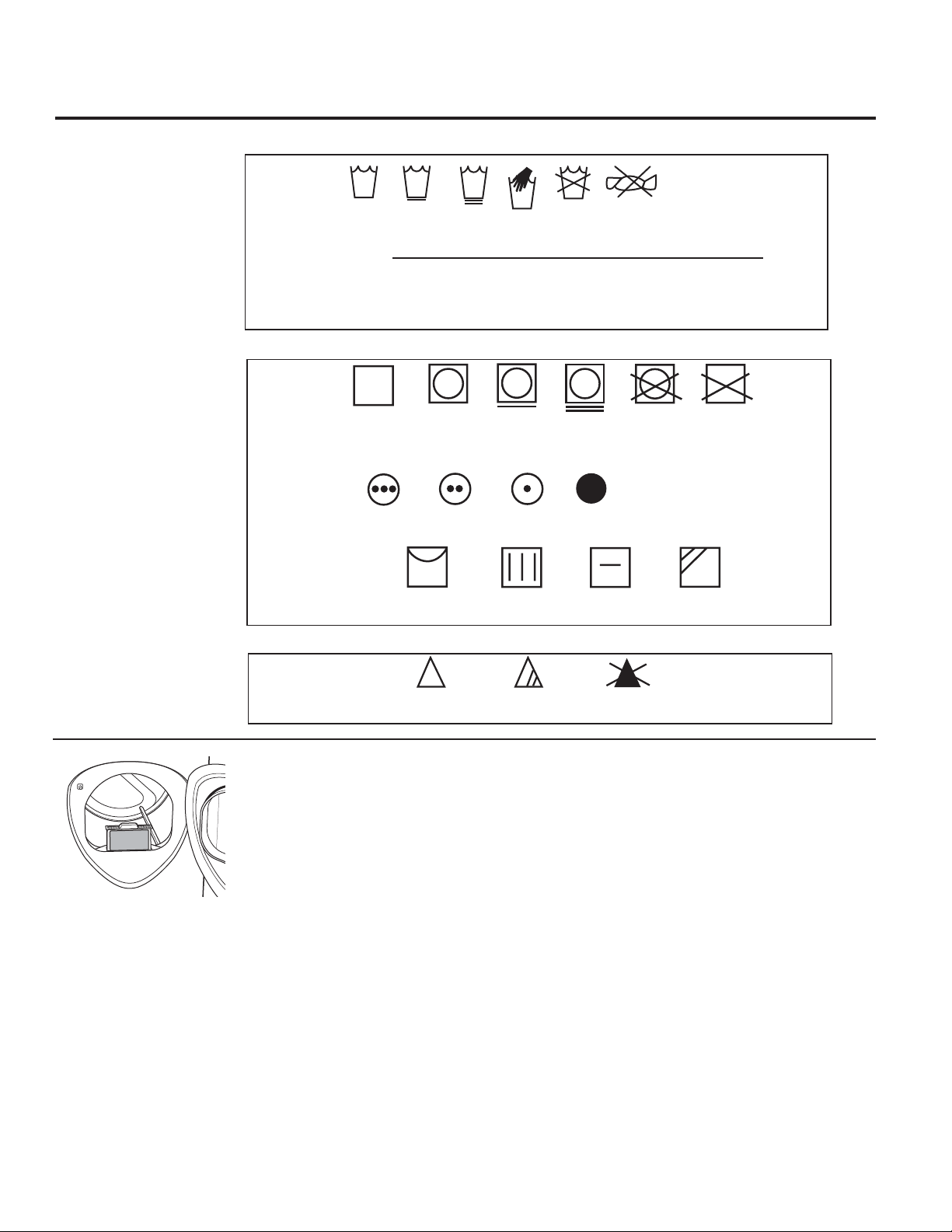
116
Cómo usar la secadora.
Cuidado y limpieza de la secadora
Interior y conducto de la secadora: Un técnico
calificado debe limpiar la parte interna del artefacto y
el conducto de salida una vez por año.
Parte externa: Limpie los derrames o compuestos de
limpieza con un paño húmedo. El panel de control y
los acabados de la secadora pueden resultar dañados
por productos removedores de manchas y suciedad
utilizados como tratamiento previo al lavado. Aplique
estos productos lejos de la secadora. La tela luego
puede lavarse y secarse de manera normal. Los daños
provocados a su secadora por estos productos no
están cubiertos por la garantía.
No toque la superficie o la pantalla con objetos afilados.
El filtro de pelusas: Limpie el filtro de pelusas antes de
cada uso. Quítelo tirando hacia arriba. Pase los dedos
por el filtro. Puede formarse una acumulación cerosa
en el filtro de pelusas por utilizar suavizantes de telas
para secadora en hojas. Para quitar esta acumulación,
lave el filtro de pelusas en agua tibia jabonosa. Seque
bien y vuelva a colocar. No opere la secadora sin el
filtro de pelusas en su lugar.
Pase la aspiradora al filtro de pelusas si nota un cambio
en el desempeño de la secadora.
Acero inoxidable: Para limpiar superficies de acero
inoxidable, utilice un paño húmedo con un limpiador
suave y no abrasivo para superficies de acero
inoxidable. Quite los restos de limpiador y luego seque
con un paño limpio.
El acero inoxidable utilizado para fabricar el tambor
de la secadora ofrece la mayor confiabilidad de una
secadora GE. Si el tambor de la secadora se raya o
abolla durante un uso normal, éste no se oxidará o
corroerá. Estas imperfecciones de la superficie no
afectan la función o durabilidad del tambor.
La campana de salida: Verifique con un espejo que las
solapas internas de la campana se muevan libremente
durante el funcionamiento. Verifique que no haya vida
silvestre (pájaros, insectos, etc.) dentro del conducto o
la campana.
Etiquetas sobre
cuidado de las telas
A continuación incluimos los
“símbolos” de las etiquetas
sobre cuidado de las telas
que podrían afectar a las
ropas que está lavando.
Etiquetas de Lavado
Tumble
dry
Dry
Normal
Permanent Press/
wrinkle resistant
Gentle/
delicate
Do not tumble dry
Do not dry
(used with
do not wash)
Heat
setting
High
Medium
Low
No heat/air
Special
instructions
Line dry/
hang to dry
Drip dry
Dry flat
In the shade
Etiquetas de Secado
Secado
Secado en
secadora
Normal
No secar en
secadora
Configuración
de calor
Alto Medio Bajo Sin calor/aire
Instrucciones
especiales
Colgar para
secar
Secado por
goteo
Secar
extendido
À la sombra
Suave/
delicado
Planchado
permanente/
resistente a
las arrugas
No secar
(utilizado con
no lavar)
Machine
wash
cycle
Normal
Permanent Press/
wrinkle resistant
Gentle/
delicate
Hand wash
Do not wash Do not wring
Temperatura
objetivo del
agua en
carga frontal
Temperatura Control automático
Categoría objetivo del agua de temperatura
Agua fría del grifo Temperatura del agua de entrada No utilizado
Fría 27°C/80°F Utilizado
Tibia 40°C/105°F Utilizado
Caliente 50°C/120°F Utilizado
Desinfectar 70°C/160°F Utilizado
Etiquetas de la Lejía
Símbolos de
blanqueador
Cualquier blanqueador
(cuando se necesita)
Sólo blanqueador sin cloro
(cuando se necesita)
No use blanqueador
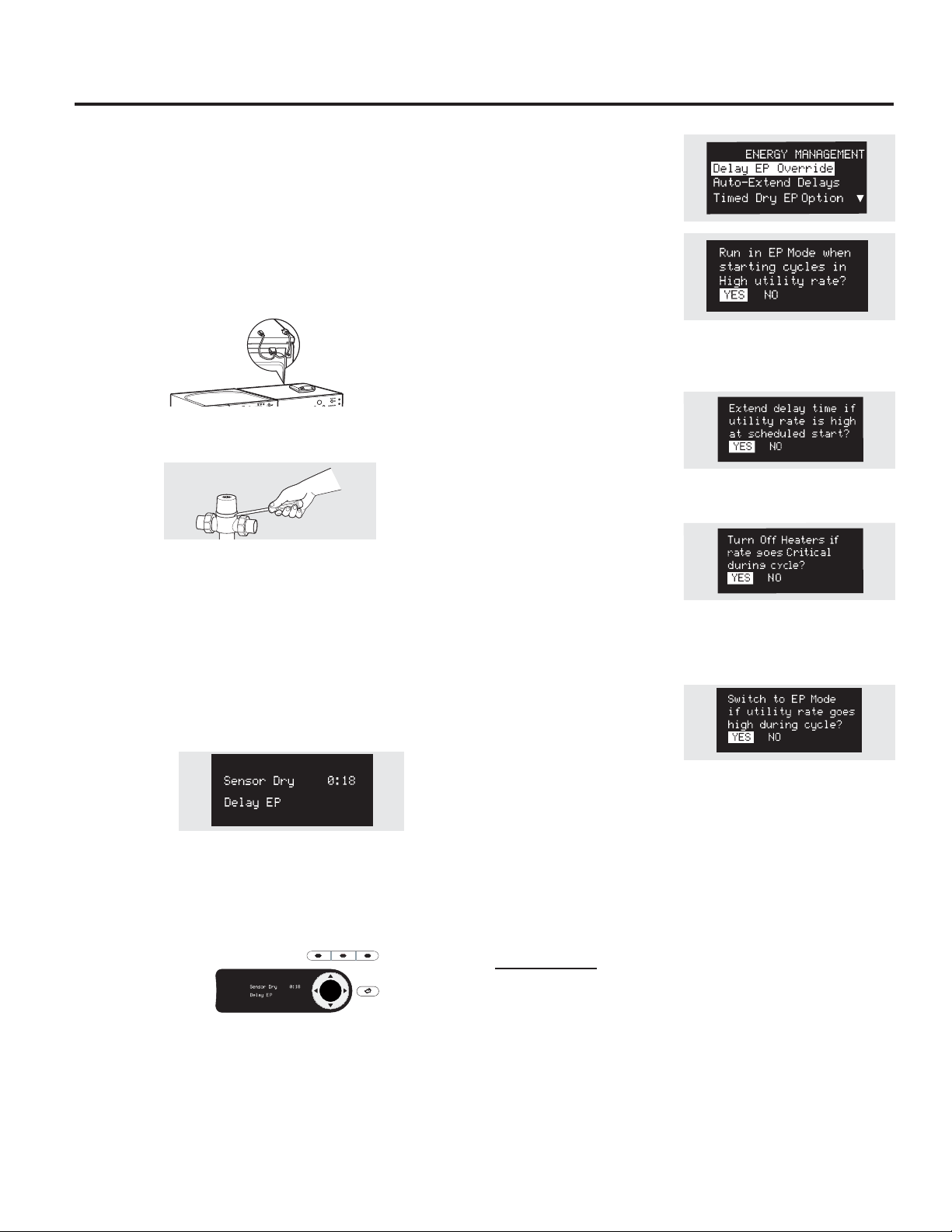
Los modelos PFDS450, PFDS455, PFDN440 y PFDN445 son compatibles con
GE Smart Appliance Module (SAM) (Módulo de Aparato Inteligente de GE) que
puede adquirirse en forma separada. Comuníquese con su empresa local de
servicios públicos o visite www.GEAppliances.com/smart-appliances para ver si
en su área se está utilizando la tecnología de Respuesta ante Demanda (DR).
Las siguientes características de respuesta ante demanda se encuentran
disponibles como parte de un programa de prueba piloto con la empresa
local de servicio público a fin de ayudar a los consumidores a reducir el uso de
electricidad durante el pico de demanda.
Instalación
La ubicación preferida para la instalación del módulo es sobre la secadora
de ropa. Adjuntos con las instrucciones que vienen con el módulo encontrará
detalles de cómo conectar los cables.
Espere 5 minutos; luego presione el botón “Settings” (configuraciones).
Desplácese por la pantalla y busque la pantalla de administración de energía
cono puede verse abajo.
Esta pantalla significa que el módulo se encuentra bien conectado y que usted
puede comenzar a utilizar su aparato inteligente siguiendo las instrucciones de
abajo. Si la pantalla de administración de energía no se encuentra disponible,
consulte la guía de identificación y solución de problemas del módulo de SAM.
Guía Rápida
Existen 4 niveles de energía disponibles: Critical (crítico), High (alto), Medium
(medio) y Low (bajo). En los niveles Medium (medio) y Low (bajo), la unidad
funciona de manera normal. Los siguientes pasos muestran cómo reacciona la
unidad durante el inicio en los niveles de energía Critical (crítico) y High (alto).
Opción 1 (Delay Eco) (Retardo ecológico)
Durante los inicios en los niveles Critical (crítico) y High (alto), a unidad retardará
el inicio hasta que los niveles alcancen Medium (medio) o Low (bajo). Presione el
botón START/PAUSE (iniciar/pausa).
Opción 2 (Override Delay EP) (Cancelar retardo ecológico)
Para accionar la unidad cuando puede verse Delay EP (retardo ecológico),
presione el botón DELAY START (inicio retardado) para apagar el retardo. Luego
presione START/PAUSE (iniciar/pausa) para comenzar el lavado. Durante un
período de nivel crítico, también se activará el Modo Crítico de Respuesta**
para potenciar al máximo el ahorro de energía. Podrá verse EP.
Opción 3 (Cancelar “e” DRY) (SECADO “e”)
Después de cancelar la función de retardo, presione el botón “e” DRY para
desactivar la configuración “e” DRY. Presionar la tecla START/PAUSE (inicio/
pausa) iniciará el ciclo seleccionado.
Durante un período de nivel crítico, se activará el Modo Crítico de Respuesta**
para potenciar al máximo el ahorro de energía. Podrá verse EP.
**Nota: El Modo Crítico de Respuesta puede desactivarse en cualquier
momento presionando y sosteniendo el botón “e” DRY durante 3 segundos. EP
desaparecerá de la pantalla.
Menú de Configuraciones
Presione SETTINGS (configuraciones);
luego seleccione “Energy
Management” (administración de
energía).
Delay EP Override
(Cancelar retardo ecológico)
Si usted está comenzando un
ciclo con un nivel de energía de la
empresa de servicio público Critical
(crítico) o High (alto), esta opción
permite que la unidad funcione
automáticamente en EP Cycle (ciclo ecológico). Esta configuración actúe con
menos energía que los ciclos normales. La configuración predeterminada es
YES (sí).
Auto-Extend Delays (Retardos de
prolongación automática)
Si se selecciona un retardo
temporizado, esta opción permite la
prolongación del inicio programado
si el nivel de energía de la empresa
de servicio público se encuentra en Critical (crítico) o High (alto) en el inicio
programado. La configuración predeterminada prolongará estos ciclos en forma
automática.
Critical Rate Option (Opción de
Nivel Crítico)
Esta opción le permite a su
aparato inteligente responder a
una información de nivel crítico
activando automáticamente
el Modo Crítico de Respuesta. El Modo de Respuesta ante nivel Crítico se
encuentra diseñado para potenciar al máximo el ahorro de energía cuando
un ciclo está funcionando durante un período de nivel crítico. La configuración
predeterminada es YES (sí). Configurar esta opción en NO desactivará el Modo
de Respuesta ante nivel Crítico.
Timed Dry EP Option (Opción de
secado temporizado ecológico)
Si la unidad está funcionando
en el Modo Timed Dry (secado
temporizado) y nivel de energía de la
empresa de servicio público pasa a
Critical (crítico) o High (alto), la unidad conservará la energía reduciendo el calor si
se selecciona YES (sí) (predeterminado). Si se selecciona NO, la unidad funcionará
normalmente.
NOTA: Cuando se selecciona YES (sí) (predeterminado), la carga puede quedar
húmeda al final del ciclo.
Para que las características de aparato inteligente de su electrodoméstico
funcionen, debe instalarse equipamiento adicional para poder conectarse
con la empresa local de servicio público. Ese equipamiento puede venderse
por separado y/o se encuentra disponible a través de su empresa de servicio
público como parte de un programa de prueba piloto. Consulte a su empresa
de servicio público sobre la existencia de un programa de prueba piloto en
su área y solicite todos los detalles.
NOTA IMPORTANTE: Al finalizar el programa de prueba piloto o si usted se muda
a un área donde el programa no se encuentra disponible, las características
de respuesta ante demanda no pueden activarse o utilizarse en el aparato.
El aparato funcionará de modo normal después de que el equipamiento de
respuesta ante demanda se haya desactivado o desconectado.
APARATO INTELIGENTE. (en algunos modelos) GEAppliances.com
ENTER
DELAY
STAR T
e
DRY
DRYER
RACK
BACKBACK
117
Si tiene alguna pregunta, llame a 800.GE.CARES (800.432.2737) o visite nuestro sitio Web en: GEAppliances.com
En Canadá, llame a 1.800.561.3344 o visite www.GEAppliances.ca
118
ANTES DE COMENZAR
Lea estas instrucciones por completo y con
detenimiento.
•
IMPORTANTE – Guarde estas
instrucciones para el uso de inspectores
eléctricos locales.
•
IMPORTANTE – Cumpla con todos los
códigos y ordenanzas vigentes.
•
Instale la secadora de acuerdo con las
instrucciones del fabricante y los códigos locales.
• Nota al instalador – Asegúrese de dejar estas
instrucciones con el consumidor.
• Nota al usuario – Conserve estas instrucciones
para referencia futura.
•
La instalación de la secadora debe efectuarla un
instalador calificado.
•
Esta secadora debe tener una salida al exterior.
•
Antes de que la secadora antigua sea retirada del
servicio o eliminada, quítele la puerta.
•
La información sobre reparaciones y el diagrama
del cableado se encuentran en la consola de
control.
•
No permita que niños se suban o se metan dentro
del artefacto. Se requiere una supervisión estricta
cuando el aparato es utilizado cerca de niños.s.
•
El instalador tiene la responsabilidad de efectuar
una instalación adecuada.
•
La garantía no cubre las fallas del producto
debido a una instalación incorrecta. .
• Instale la secadora en lugares donde la
temperatura sea mayor a 50°F para un
funcionamiento satisfactorio del sistema de
control de la secadora.
• Quite y descarte el conducto existente de plástico
o de papel de aluminio y coloque un conducto
aprobado por UL.
Instrucciones
Secadora
de instalación
ADVERTENCIA:
Riesgo de incendio
• Para reducir el riesgo de una lesión grave o de
muerte, cumpla con todas las instrucciones de
instalación.
•
La instalación de la secadora debe efectuarla un
instalador calificado.
• Instale la secadora de ropa de acuerdo con estas
instrucciones y en cumplimiento con los códigos
locales
•
Esta secadora debe tener una salida al exterior.
•
Utilice sólo un conducto rígido de metal de un
diámetro de 4” dentro del gabinete de la secadora
y use sólo un conducto de transición aprobado por
UL entre la secadora y el conducto doméstico.
•
NO instale una secadora de ropa con conductos de
plástico flexible. Si se instala un conducto flexible de
metal (semi rígido o de tipo papel de aluminio), debe
estar aprobado por UL e instalarse de acuerdo con
las instrucciones de “Cómo conectar la secadora a
la ventilación doméstica” de la página 26 de este
manual. Los materiales de los conductos flexibles
a menudo se desploman, se aplastan y atrapan
pelusas. Estas condiciones obstruyen la corriente
de aire de la secadora e incrementan el riesgo de
incendio.
•
No instale o almacene este aparato en un
lugar donde se vea expuesto al agua y/o a las
inclemencias del tiempo.
•
Guarde estas instrucciones. (Instaladores:
Asegúrense de dejar estas instrucciones al
consumidor).
SÓLO PARA MODELOS A GAS:
NOTA: La instalación y servicio técnico de esta
secadora deben realizarlos un instalador calificado,
una agencia de servicios o el proveedor de gas.
En la Mancomunidad de Massachusetts:
•
Este producto debe instalarlo un plomero
matriculado o un instalador de gas.
•
Cuando use válvulas esféricas de apagado de
gas, deberán ser del tipo de manija en T.
•
Si se usa una conexión flexible para gas, ésta no
debe superar los 3 pies.
PARA SU SEGURIDAD:
PFDS450 / PFDS455 /PFDN440 / PFDN445 /
PFMS450 / PFMS455 / PFMN440 / PFMN445
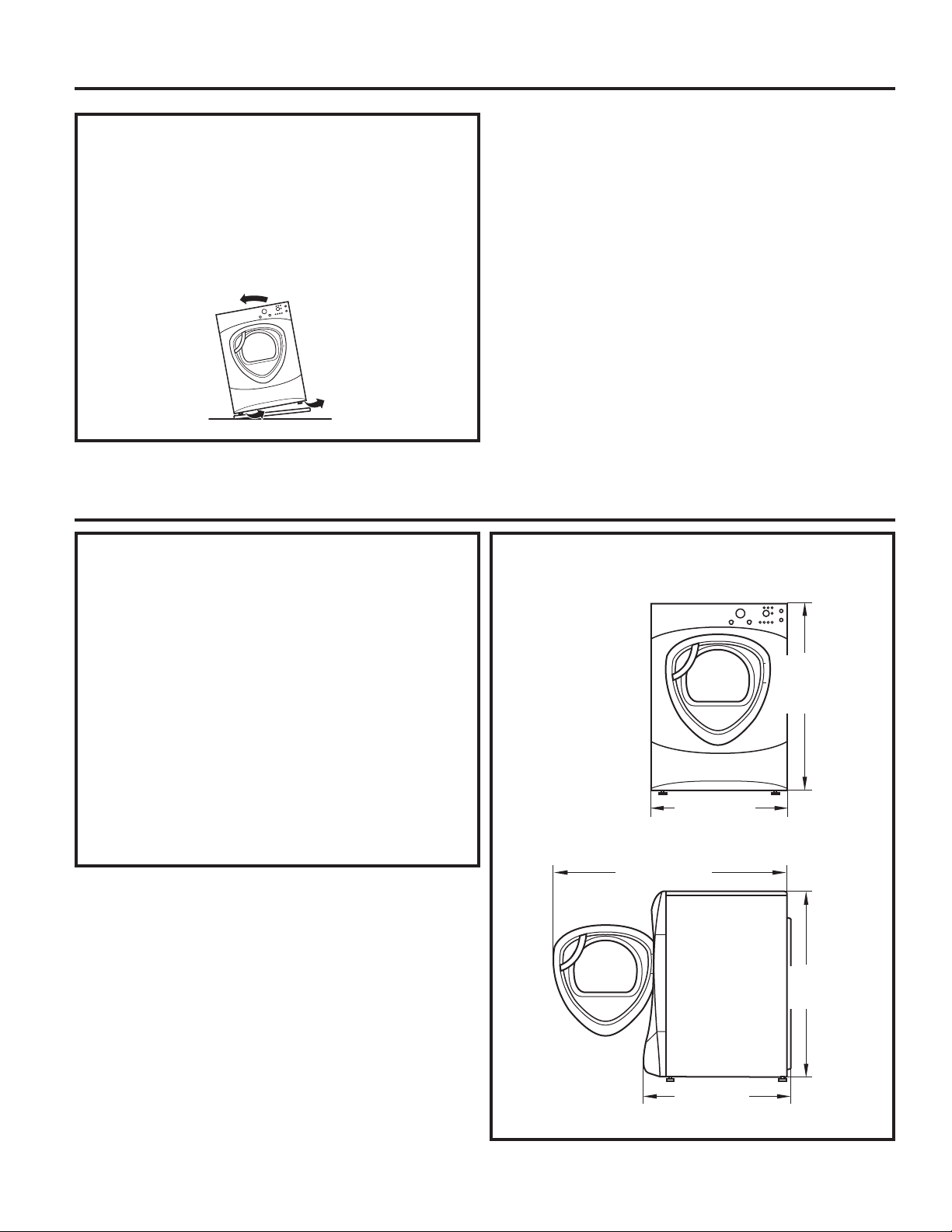
Instrucciones de instalación
CÓMO DESEMPACAR LA SECADORA
Incline la secadora de costado y saque los paños
de espuma de embalaje tirando de los costados y
quitándolos de las patas de la secadora. Asegúrese
de quitar todas las piezas de espuma de las patas.
Saque la bolsa que contiene la información y cable
serial.
DIMENSIONES DE LA SECADORA
51″
(129.5 cm)
39.1″
(993 cm)
32.34″
(847 cm)
27″
(68.6 cm)
39.1″
(993 cm)
27”
(68,6 cm)
39,5”
(100,3 cm)
33,5”
(85,1 cm)
39,5”
(100,3 cm)
Visión lateral
Visión frontal
UBICACIÓN DE SU SECADORA
ESPACIO LIBRE MÍNIMO EN OTROS
ESPACIOS QUE NO SEAN INSTALACIONES
EN NICHOS O ARMARIOS
Los espacios libres mínimos respecto de
superficies combustibles y de aberturas de aire
son:
•
Un espacio libre de 0 pulgadas sobre ambos
lados
•
1 pulgada hacia el frente
•
3 pulgadas hacia atrás
Debe tenerse en cuenta un espacio libre
adecuado para un funcionamiento y reparación
correctos.
53”
(134,6 cm)
119
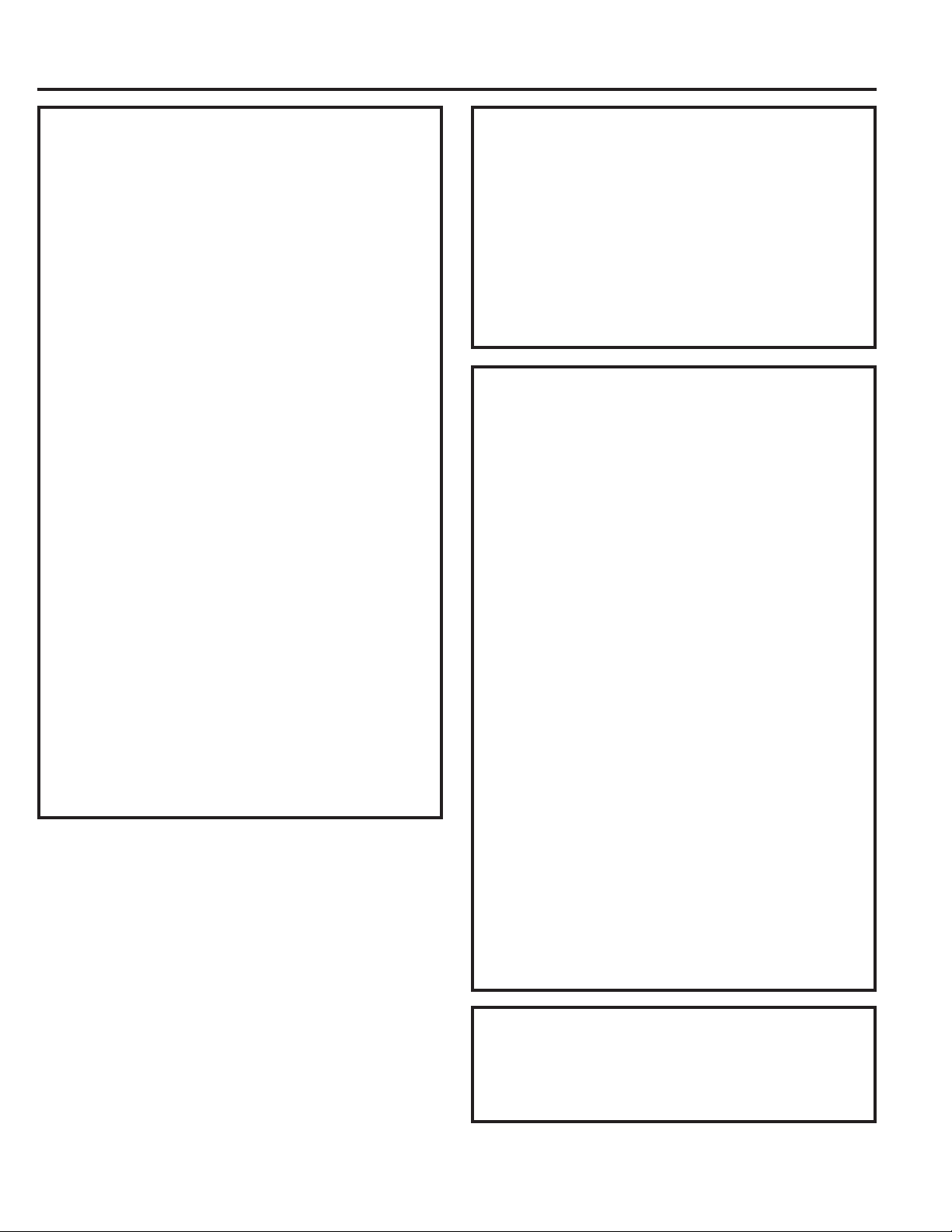
120
Instrucciones de instalación
REQUERIMIENTOS PARA INSTALACIÓN
EN NICHOS O ARMARIOS
• Su secadora puede instalarse en un nicho o
armario, como se indica en la etiqueta de la parte
trasera del aparato.
•
Esta secadora DEBE tener una ventilación al
exterior. Ver la sección SALIDA AL EXTERIOR DE LA
SECADORA.
•
El espacio libre mínimo entre el armario de
la secadora y las paredes adyacentes u otras
superficies es:
0” sobre ambos lados
3” sobre el frente y la parte trasera
•
El espacio vertical mínimo desde el piso a los
estantes superiores, gabinetes, cielorrasos, etc.,
es de 52”.
•
Las puertas del armario deben contar con rejillas
u otro tipo de ventilación y tener por lo menos
60 pulgadas cuadradas de espacio abierto
igualmente distribuido. Si el armario incluye una
lavadora y una secadora, las puertas deben
contener un mínimo de 120 pulgadas cuadradas
de espacio abierto distribuido uniformemente.
•
El armario debe tener ventilación hacia el exterior
para evitar la acumulación de gas en caso de que
haya gas en la línea de suministro.
•
No deberán instalarse otros artefactos a
combustible en el mismo armario con la secadora
(sólo modelos a gas).
NOTA: CUANDO EL CONDUCTO DE SALIDA ESTÁ
UBICADO EN LA PARTE TRASERA DE LA SECADORA,
EL ESPACIO LIBRE MÍNIMO DESDE LA PARED DEBE
SER 5.5 PULGADAS.
INSTALACIÓN EN BAÑOS O
DORMITORIOS
• Esta secadora DEBE tener una ventilación
al exterior. Ver SALIDA AL EXTERIOR DE LA
SECADORA.
•
La instalación debe cumplir con los códigos
locales o, si no los hubiera, con el CÓDIGO
NACIONAL ELÉTRICO, ANSI/NFPA NC. 70 (para
secadoras eléctricas) o el CÓDIGO NACIONAL DE
GAS, ANSI Z223 (para secadoras a gas).
INSTALACIÓN EN CASAS MÓVILES O
PREFABRICADAS
• La instalación debe cumplir con la NORMA
SOBRE CONSTRUCCIÓN Y SEGURIDAD DE CASAS
PREFABRICADAS, TÍTULO 24, PARTE 32-80 o,
cuando dicha norma no sea aplicable, con la
NORMA NACIONAL ESTADOUNIDENSE PARA
CASAS MÓVILES, Nº 501B.
•
La secadora DEBE tener ventilación al exterior
con la terminación bien sujeta a la estructura
de la casa móvil. (Ver SALIDA AL EXTERIOR DE LA
SECADORA).
•
La ventilación NO DEBE terminar debajo de una
casa móvil o prefabricada.
•
El material del conducto de ventilación DEBE SER
METAL.
•
SÓLO PARA MODELOS A GAS: DEBE utilizarse el KIT
14-D346-33 para conectar bien la secadora a la
estructura.
•
SÓLO PARA MODELOS A GAS: La ventilación
NO DEBE conectarse a ningún otro conducto,
ventilación o chimenea.
•
No utilice tornillos para placas de metal u otros
dispositivos de sujeción que se extiendan al
interior de la ventilación de salida.
•
Debe contar con una abertura con un espacio
libre de por lo menos 25 pulgadas cuadradas
para el ingreso de aire exterior dentro del cuarto
de la secadora.
INSTALACIÓN EN GARAJES (SI PERMITIDO
POR LOS CÓDIGOS LOCALES)
•
Las secadoras instaladas en garajes deben
elevarse 18 pulgadas (46 cm) desde el piso
.
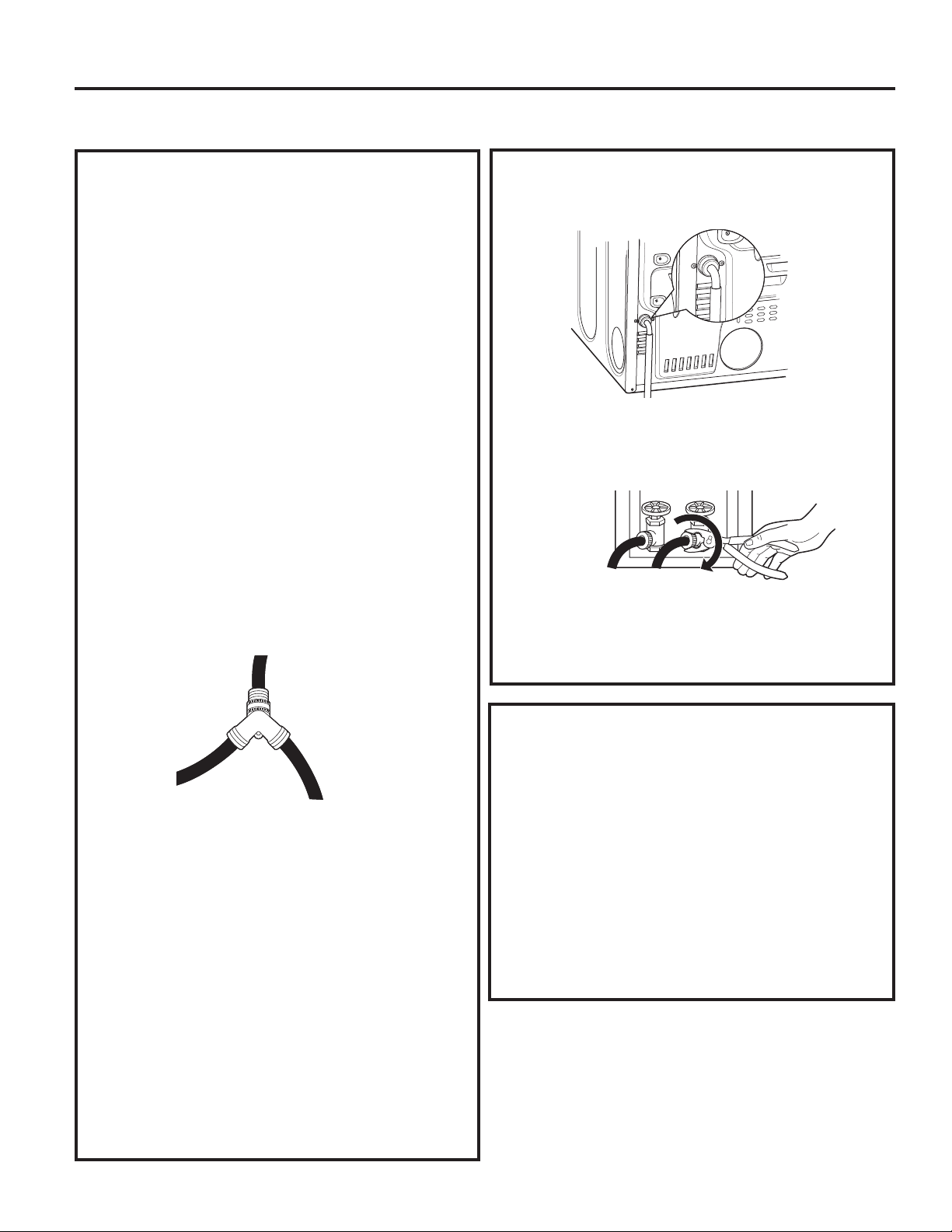
Instrucciones de instalación
CÓMO CONECTAR MANGUERAS DE ENTRADA
CÓMO CONECTAR MANGUERAS DE
ENTRADA
Para producir vapor, la secadora debe conectarse
al suministro de agua fría. Ya que la lavadora
también debe conectarse al agua fría, debe
introducirse un conector en “Y” para permitir que
ambas mangueras de entrada puedan utilizarse al
mismo tiempo.
NOTA: Utilice las nuevas mangueras de entrada
provistas; nunca utilice mangueras viejas.
1. Cierre el grifo de agua fría. Quite la manguera
de entrada de la lavadora del conector de la
válvula de llenado (fría).
2. Asegúrese de que la arandela plana de goma se
encuentre en su lugar y ajuste la unión hembra
de la manguera corta en el conector de la
válvula de llenado de la lavadora. Ajuste a mano
hasta que estén firmemente asentada.
3. Sujete el extremo hembra del conector en
“Y” a la unión macho de la manguera corta.
Asegúrese de que la arandela plana de goma se
encuentre en su lugar.
Ajuste a mano hasta que
esté firmemente asentada.
4. Introduzca el filtro en la unión de la manguera
de entrada de la lavadora. Si la arandela plana
de goma ya se encuentra en su lugar, quítela
antes de instalar el filtro. Sujete esta unión a
un extremo macho del conector en “Y”. Ajuste
a mano hasta que esté firmemente asentada.
5. Asegúrese de que la arandela plana de goma
se encuentre en su lugar y sujete la manguera
larga de entrada de la secadora al otro extremo
macho del conector en “Y”. Ajuste a mano hasta
que esté firmemente asentada.
6. Asegúrese de que la arandela plana de goma se
encuentre en su lugar y sujete el otro extremo
de la manguera larga de entrada al conector
de la válvula de llenado en la parte inferior del
panel trasero de la secadora. Ajuste a mano
hasta que esté firmemente asentada.
CÓMO CONECTAR MANGUERAS DE
ENTRADA (cont.)
7. Utilizando alicates, ajuste todas las uniones con
un giro adicional de dos tercios.
NOTA: No ajuste de más. Pueden dañarse las
uniones.
8. Abra el grifo de agua.
9. Controle la presencia de pérdidas alrededor
del conector en “Y”, el grifo y las uniones de las
mangueras.
REQUISITOS DE SUMINISTRO DE AGUA
Los grifos de agua caliente y fría DEBEN instalarse
dentro de las 42 pulg. (107 cm) de la entrada de
agua de la lavadora. Los grifos DEBEN ser del tipo de
manguera de jardín de 3/4 pulg. (1.9 cm) para que
las mangueras de entrada puedan conectarse. La
presión de agua DEBE hallarse entre 10 y 120 libras
por pulgada cuadrada. La compañía de agua puede
informarle sobre la presión de agua.
NOTA: Se recomienda el uso de un suavizante de
agua para reducir la acumulación de sarro dentro
del generador de vapor si el suministro doméstico
contiene agua muy dura.
121
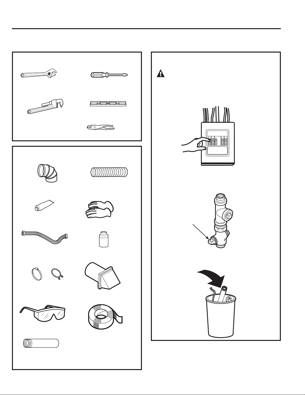
122
CÓMO CONECTAR UNA SECADORA A GAS (si se cuenta con una
secadora eléctrica, saltear este paso)
Llaves ajustables de
10” (2)
Llave para tubos de
8”
Destornillador de
lados planos
Nivel
Instrucciones de instalación
HERRAMIENTAS NECESARIAS
PARA SU SEGURIDAD:
ADVERTENCIA:
Antes de comenzar la instalación, apague el
disyuntor o quite los fusibles de la secadora de la
caja eléctrica. Verifique que el cable de la secadora
esté desenchufado del tomacorriente.
Gire a la posición OFF (apagado) la válvula de gas
de la secadora de la línea de suministro.
Desconecte y elimine el conector flexible de gas y
el material del conducto.
Válvula
de cierre
MATERIALES NECESARIOS
Codo de metal de 4”
diámetro
Compuesto para
tuberías
Conector de tubería de
gas flexible
Abrazaderas de tubería
(2) o abrazaderas de
resorte (2)
Gafas de seguridad
Conducto de metal de 4”
diámetro (recomendado)
Conducto de metal
flexible de 4” diámetro
(si fuese necesario)
Guantes
Solución jabonosa para
detección de pérdidas
Campana de salida
Cinta aislante
Pinzas
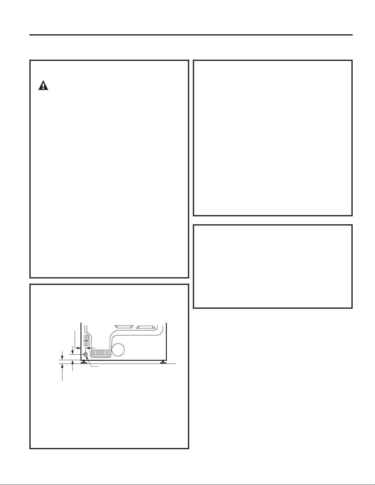
Instrucciones de instalación
REQUERIMIENTOS DE GAS
ADVERTENCIA:
• La instalación debe cumplir con códigos o
ordenanzas locales, o si no las hubiera, con el
CÓDIGO NACIONAL DE GAS, ANSI Z223.1/NFPA
54, o con el Código de Instalación de Gas Natural
y Propano CSA B149.1.
•
Esta secadora a gas está equipada con un
montaje de válvula y quemador para utilizar sólo
con gas natural. Mediante el kit de conversión
14-A048, la organización de atención local puede
convertir esta secadora para su uso con gas
propano (LP). TODAS LAS CONVERSIONES DEBEN
LLEVARLAS A CABO PERSONAL CAPACITADO Y
CALIFICADO EN CUMPLIMIENTO CON CÓDIGOS
LOCALES Y REQUERIMIENTOS DE ORDENANZAS.
•
La secadora debe desconectarse del sistema de
tubería de suministro de gas durante cualquier
prueba de presión del sistema con una presión
de prueba mayor a 0.5 PSI (3.4 KPa).
•
La secadora debe aislarse del sistema de tubería
de suministro de gas cerrando la válvula de cierre
del equipo durante cualquier puesta a prueba
del sistema en presiones de prueba iguales o
menores a 0.5 PSI (3.4KPa).
CONEXIÓN DE SUMINISTRO DE GAS DE
LA SECADORA
SUMINISTRO DE GAS ROSCA MACHO NPT
DE 3/8”
NOTA: Agregue a la dimensión
vertical la distancia entre la parte
inferior del gabinete y el piso.
SUMINISTRO DE GAS
• Debe instalarse una toma a rosca de 1/8” NPT,
accesible para una conexión del manómetro de
prueba, inmediatamente en sentido ascendente
de la conexión de suministro de gas hacia la
secadora. Si tiene dudas sobre la instalación de la
toma, comuníquese con su empresa proveedora
de gas local.
•
La línea de suministro debe ser de tubería rígida
de 1/2” y debe contar con un cierre accesible
dentro de los 6 pies de la secadora, dentro de la
misma habitación donde se encuentra la misma.
•
Utilice compuesto para rosca de tubería
apropiado para gas natural o LP o utilice cinta de
Teflon
®
.
•
Una el conector de metal flexible a la secadora y
al suministro de gas.
EN LA MANCOMUNIDAD DE
MASSACHUSETTS
• Este producto debe instalarlo un plomero
matriculado o un instalador de gas.
•
Cuando use válvulas esféricas de apagado de
gas, deberán ser del tipo de manija en T.
•
Si se usa una conexión flexible para gas, ésta no
debe superar los 3 pies.
2
5
ø8” (6,7 cm)
2” (5,1
cm)
Debe utilizar un conector flexible metálico
listado por ANSI Z21.24/CSA 6.10. La longitud del
conector no excederá 3 pies.
123
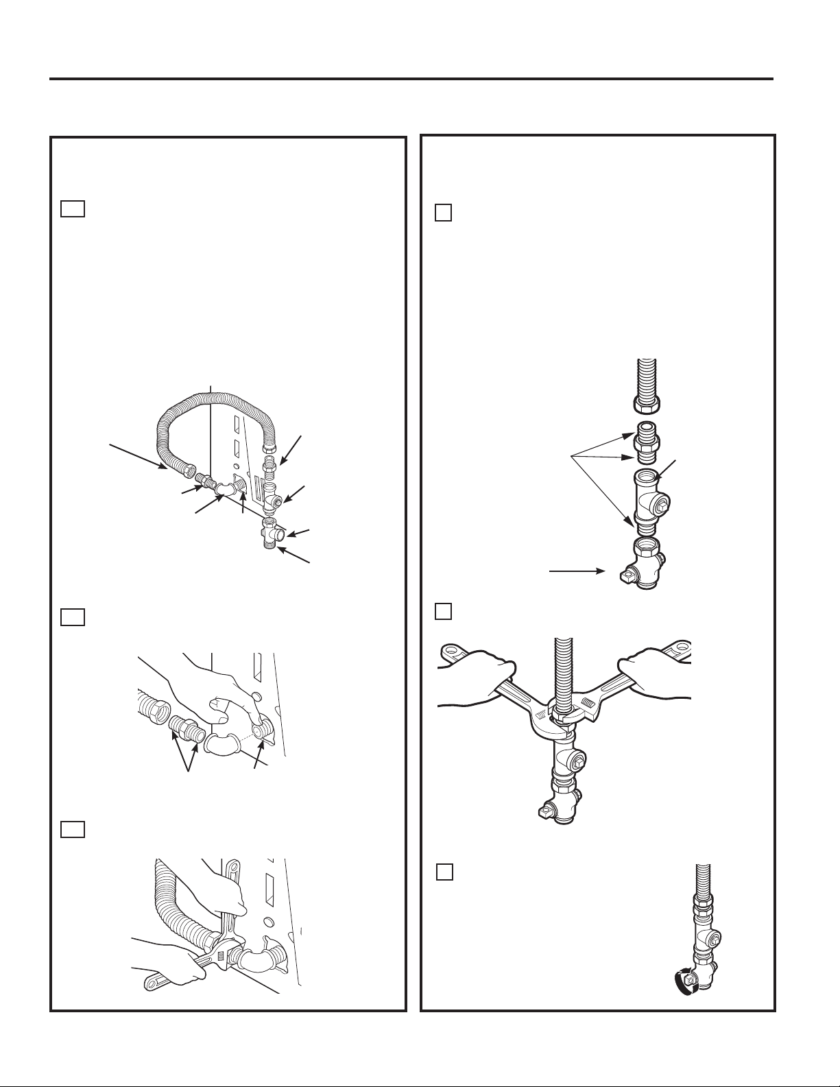
124
Instale una toma a rosca de 1/8” NPT en la
válvula de apagado de la tubería de gas de la
secadora para controlar la presión de gas en la
entrada.
Instale un adaptador de unión cónica en la toma
a rosca.
NOTA: Aplique compuesto para tubería o cinta
Teflon
®
a las roscas del adaptador y a la toma.
Instrucciones de instalación
Una el conector de tubería de gas de metal
flexible al adaptador.
B
Ajuste la conexión de tubería flexible de gas,
utilizando dos llaves ajustables.
C
D
Ajuste todas las conexiones mediante dos
llaves ajustables. No ajuste de más.
E
CÓMO CONECTAR LA SECADORA AL
SUMINISTRO DE GAS (cont.)
Cierre la válvula de apagado
del gas.
F
Aplique compuesto
para tubería o cinta
Teflon
®
en todas las
roscas macho.
Válvula de apagado
Toma a
rosca
CÓMO CONECTAR LA SECADORA AL
SUMINISTRO DE GAS
Instale un codo hembra NPT de 3/8” al final de la
entrada de gas de la secadora.
Instale un adaptador de unión cónica de 3/8” al
codo hembra.
IMPORTANTE: Utilice una llave para tubos para
sostener bien el extremo de la entrada de gas
de la secadora para no doblar la entrada.
NOTA: Aplique compuesto para tubería o cinta
Teflon
®
a las roscas del adaptador y la entrada
de gas de la secadora.
A
Aplique compuesto para tubería al adaptador
y a la entrada de gas de la secadora.
Codo
Adaptador
Elementos no incluidos
Adaptador
Tapón de tubería
de 1/8” NPT
para controlar la
presión de gas en
la entrada
Válvula
de apagado
Tamaño de
tubería de por
lo menos 1/2”
3/8” NPT
Nuevo
conector de
línea de gas
de metal
CÓMO CONECTAR UNA SECADORA A GAS (cont.)
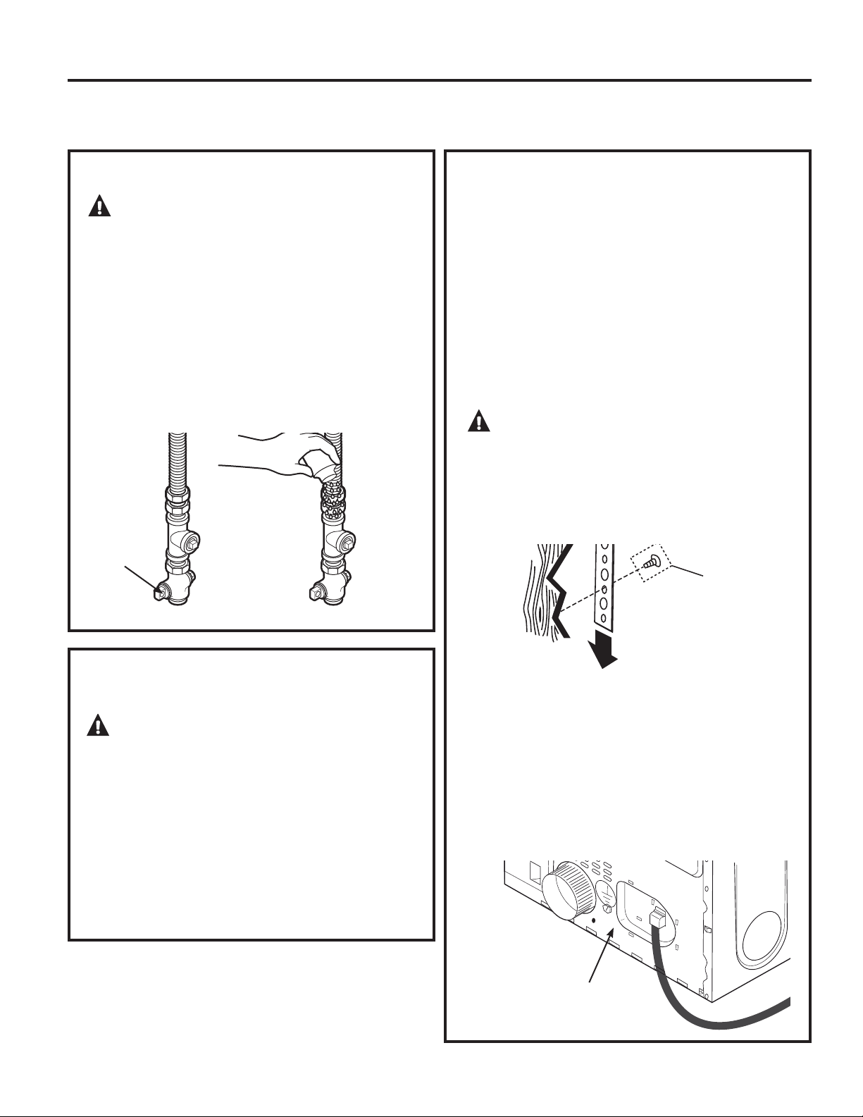
Verifique que
haya una
conexión a tierra
adecuada antes
del uso.
CÓMO CONECTAR UNA SECADORA ELECTRICA
(si se cuenta con una secadora a gas, saltear este paso)
Instrucciones de instalación
PRUEBA DE PÉRDIDAS
Abra la
válvula
de gas
CONEXIÓN ELÉCTRICA INFORMACIÓN
SOBRE LAS SECADORAS A GAS
ADVERTENCIA: Para reducir el
riesgo de incendio, descarga eléctrica y lesiones
personales:
•
No utilice un cable de extensión o un enchufe
adaptador con este artefacto.
•
La secadora debe contar con una conexión
eléctrica a tierra en cumplimiento con los códigos
y ordenanzas locales, o si éstos no existieran, de
acuerdo con el CÓDIGO ELÉCTRICO NACIONAL,
ANSI/NFPA NO. 70 o el Código Eléctrico
Canadiense CSA C22.1.
REQUERIMIENTOS ELÉCTRICOS PARA
SECADORAS A GAS
Este artefacto debe contar con un suministro de
120V, 60Hz, debe estar conectado a un circuito
derivado individual con una adecuada conexión
a tierra y deben contar con la protección de un
disyuntor o fusible de tiempo retardado de 15 o
20 amperios.
Si el suministro eléctrico provisto no cumple con
las especificaciones anteriores, se recomienda
que un electricista matriculado instales un
tomacorriente aprobado.
ADVERTENCIA: Esta secadora se
encuentra equipada con un enchufe de tres patas
(a tierra) como protección contra las descargas
eléctricas y debe enchufarse directamente en
un tomacorriente de tres patas con adecuada
conexión a tierra. No corte o quite la terminal de
conexión a tierra del enchufe.
Si los códigos locales lo permiten, puede agregarse
un cable a tierra externo (no provisto), que cumpla
con los códigos locales, conectándolo al tornillo
verde a tierra de la parte trasera de la secadora y
a una conexión a tierra alternativa.
Verifique que haya una conexión a tierra
adecuada antes del uso.
Tornillo de
conexión a tierra
ADVERTENCIA: Nunca utilice una
llama abierta para detectar pérdidas de gas.
Controle todas las conexiones con una solución
jabonosa o un elemento equivalente.
Aplique una solución jabonosa. La solución para
controlar pérdidas no debe contener amoníaco, ya
que este producto puede dañar los accesorios de
bronce.
Si se detectan pérdidas, cierre la válvula, vuelva
a ajustar la junta y repita la prueba de la solución
jabonosa. and repeat the soap test.
125
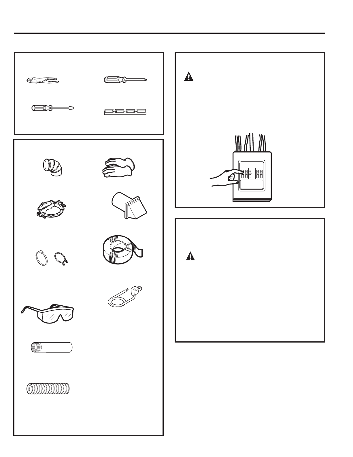
126
PARA SU SEGURIDAD:
Codo de metal de 4”
de diámetro
Alivio de tensión de
3/4” (reconocido por
UL)
Abrazaderas de
tubería de 4” (2)
o abrazaderas de
resorte de 4” (2)
Gafas de seguridad
Conducto de metal
de 4” de diámetro
(recomendado)
Conducto de metal
flexible de 4” de
diámetro (si fuese
necesario)
Guantes
Campana de salida
Cinta aislante
Kit de cable de
energía de la
secadora (no incluido
con la secadora)
Clasificado UL, de
120/240V, 30A con 3 o
4 patas. Identifique el
tipo de enchufe según
el tomacorriente de
la vivienda antes de
comprar el cable.
CÓMO CONECTAR UNA SECADORA ELECTRICA (cont.)
Instrucciones de instalación
CONEXIÓN ELÉCTRICA INFORMACIÓN
SOBRE LAS SECADORAS ELÉCTRICAS
ADVERTENCIA: Para reducir
el riesgo de incendio, descarga eléctrica y
lesiones personales:
•
No utilice un cable de extensión o un enchufe
adaptador con este artefacto.
•
La secadora debe contar con una conexión
eléctrica a tierra en cumplimiento con los
códigos y ordenanzas locales, o si éstos
no existieran, de acuerdo con el CÓDIGO
ELÉCTRICO NACIONAL, ANSI/NFPA NO. 70 o el
Código Eléctrico Canadiense CSA C22.1.
ADVERTENCIA:
Antes de efectuar la conexión eléctrica, desactive
los disyuntores o quite los fusibles del circuito
de la secadora de la caja eléctrica. Verifique
que el cable de la secadora esté desenchufado
del tomacorriente. NUNCA OLVIDE DE VOLVER
A COLOCAR LA TAPA DE ACCESO DEL BLOQUE
TERMINAL.
Pinzas
Destornillador de
lados planos
Destornillador
Phillips
Nivel
MATERIALES NECESARIOS
HERRAMIENTAS NECESARIAS
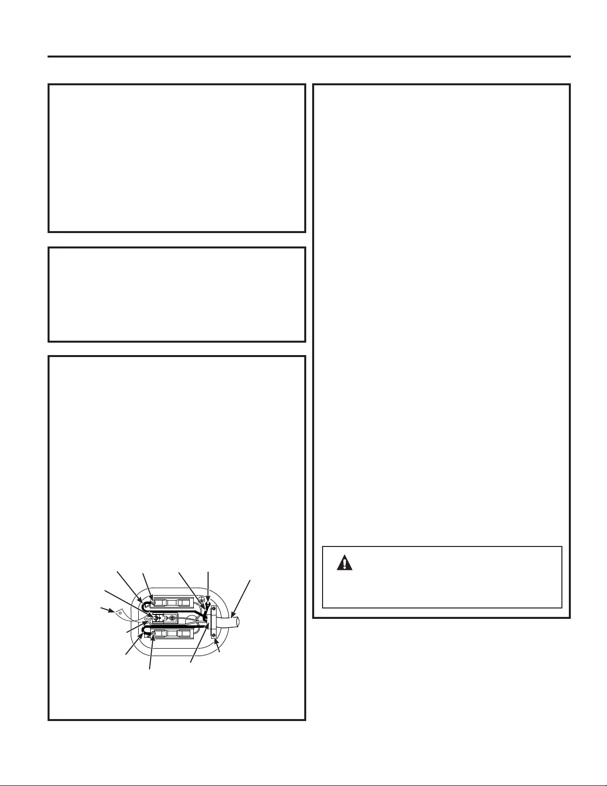
CÓMO CONECTAR LA SECADORA
USANDO UNA CONEXIÓN DE 4 CABLES
(DEBE UTILIZARSE EN INSTALACIONES
DE CASAS RODANTES)
NOTA:
Desde el 1 de enero de 1996, el Código Eléctrico
Nacional exige que las nuevas construcciones utilicen una
conexión de 4 cables a una secadora eléctrica. También
debe usarse un cable de 4 alambres cuando los códigos
locales no permiten una conexión a tierra a través de cable
neutral.
NO debe usarse una conexión de tres cables en una
construcción nueva.
Instrucciones de instalación
REQUERIMIENTOS ELÉCTRICOS PARA
SECADORAS ELÉCTRICAS
Esta secadora debe conectarse a un circuito derivado
individual, con la protección de un disyuntor o
fusible de tiempo retardado. Se requiere un circuito
de tres o cuatro cables, fase única, 120/240V ó
120/208V, 60Hz y 30 amperios.
Si el suministro eléctrico no cumple con dichas
especificaciones, entonces llame a un electricista
matriculado.
INSTRUCCIONES DE CONEXIÓN A TIERRA
Esta secadora debe conectarse a un sistema de cableado
permanente con conexión a tierra o debe utilizarse un
conductor de conexión a tierra del equipamiento con los
conductores de circuito y conectarse a la terminal de
conexión a tierra del artefacto.
CÓMO CONECTAR LA SECADORA
USANDO UNA CONEXIÓN DE 4 CABLES
(DEBE UTILIZARSE EN INSTALACIONES
DE CASAS RODANTES) (cont.)
ADVERTENCIA:
NUNCA OLVIDE DE VOLVER A COLOCAR LA
TAPA DEL BLOQUE TERMINAL.
1. Desactive el disyuntor (30 amperios) o quite el
fusible del circuito de la secadora de la caja
eléctrica.
2.
Verifique que el cable de la secadora esté
desenchufado del tomacorriente.
3.
Quite la tapa del cable de energía ubicada en la
parte trasera inferior.
4.
Quite y descarte la cinta de conexión a tierra.
Conserve el tornillo verde de conexión a tierra
para el paso 7.
5.
Instale un alivio de tensión de 3/4 pulgadas
reconocido por UL en el orificio de entrada del
cable de energía. Pase el cable de energía a
través del alivio de tensión.
6.
Conecte el cable de energía de la siguiente
manera:
A. Conecte los dos cables vivos a los tornillos
externos del bloque terminal (marcado L1 y
L2).
B. Conecte el cable neutral (blanco) al centro
del bloque terminal (marcado N).
7.
Conecte el cable a tierra del cable de energía
con el tornillo verde de conexión a tierra (orificio
sobre el soporte de alivio de tensión). Ajuste por
firmemente todos los tornillos (3) del bloque
terminal.
8.
Ajuste bien el cable de energía al alivio de
tensión.
9.
Vuelva a instalar la tapa.
127
4 conductores
de cobre
#10 AWG
mínimo o kit
de cable de
suministro
de energía de
120/240V 30A
marcado
para su
uso con
secadoras y
provisto con
terminales
de bucle
cerrado o
hembra con
extremos
hacia
arriba (no
provistos).
Cable
vivo
Cable
vivo
Cable
verde
Vuelva a
colocar el
tornillo verde
de conexión
a tierra aquí.
Neutral
(blanco)
Alivio de
tensión
de 3/4”
reconocido
por UL
Soporte
de alivio
de tensión
Tornillo
Tornillo
Tornillo
Quite la cinta
de conexión
a tierra y
descártela.
Conserve
el tornillo
verde de
conexión
a tierra.
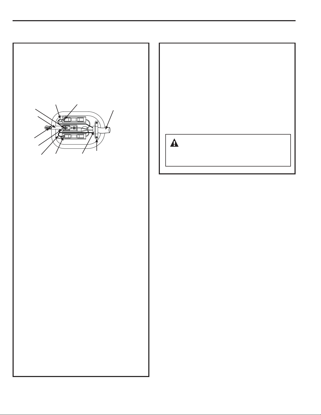
128
Instrucciones de instalación
CÓMO CONECTAR LA SECADORA
UTILIZANDO UNA CONEXIÓN DE 3
CABLES
1. Desactive el disyuntor (30 amperios) o quite el
fusible del circuito de la secadora de la caja
eléctrica.
2.
Verifique que el cable de la secadora esté
desenchufado del tomacorriente.
3.
Quite la tapa del cable de energía ubicada en la
parte trasera inferior.
4.
Instale un alivio de tensión de 3/4 pulgadas
reconocido por UL en el orificio de entrada del
cable de energía. Pase el cable de energía a
través del alivio de tensión.
5.
Conecte el cable de energía de la siguiente
manera:
A. Conecte los dos cables vivos a los tornillos
externos del bloque terminal (marcado L1 y
L2).
B. Conecte el cable neutral (blanco) al centro del
bloque terminal (marcado N).
ADVERTENCIA:
NUNCA OLVIDE DE VOLVER A COLOCAR LA
TAPA DEL BLOQUE TERMINAL.
CÓMO CONECTAR LA SECADORA
UTILIZANDO UNA CONEXIÓN DE 3
CABLES (cont.)
6. Asegúrese de que la cinta de conexión a tierra
esté conectada a la terminal neutral (central) del
bloque y al tornillo verde de conexión a tierra de la
parte trasera del gabinete. Ajuste por firmemente
todos los tornillos (3) del bloque terminal.
7.
Ajuste bien el cable de energía al alivio de
tensión.
8.
Vuelva a instalar la tapa.
CÓMO CONECTAR UNA SECADORA ELECTRICA (cont.)
Conexión de 3 cables
NO usar en Canadá.
NO usar en instalaciones en casas móviles.
NO usar en casas nuevas.
NO usar en vehículos recreativos.
NO usar en áreas donde los códigos locales
prohíben la connexión eléctrica a tierra por el
medio del cable neutral.
3 conductores
de cobre #10
AWG mínimo
o kit de cable
de suministro
de energía de
120/240V 30A
marcado para
su uso con
secadoras y
provisto con
terminales de
bucle cerrado
o hembra con
extremos hacia
arriba (no
provistos).
Cable vivo
Cable
vivo
Tornillo
verde de
conexión
a tierra
Neutral
(blanco)
Alivio de
tensión
de 3/4”
reconocido
por UL
Soporte
de
alivio
de
tensión
Tornillo
Tornillo
Tornillo
Si así lo requirieran los códigos locales, instale una conexión
a tierra externa (no provista) a metal con conexión a tierra,
tuberías de agua fría con conexión a tierra u otra conexión a
tierra establecida por un electricista calificado.
Cinta de
conexión
a tierra
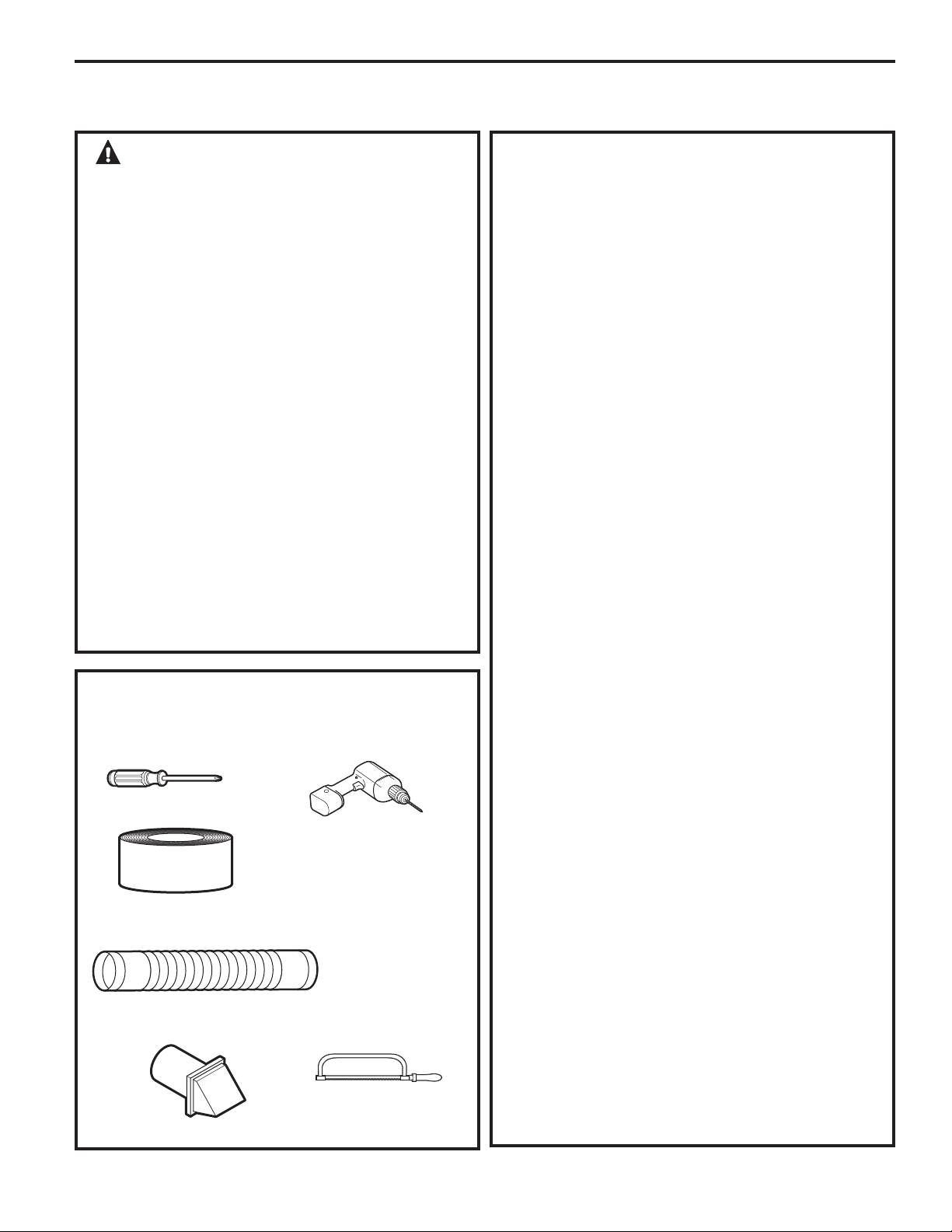
Perfore con una broca
de 1/8” drill bit (para
ventilación inferior)
Instrucciones de instalación
SALIDA AL EXTERIOR DE LA SECADORA
ADVERTENCIA: Para reducir el
riesgo de incendio o lesiones personales:
•
Esta secadora debe tener una salida al exterior.
•
Sólo use un conducto de metal.
•
No instale la boca de salida dentro de una chimenea,
ventilación de gas, bajo un piso con cerramiento,
espacio entre pisos, pared, cielorraso, dentro de
un ático, u otro espacio oculto de un edificio. La
accumulacion de pelusa podría provocar un riesgo
potencial de incendio.
•
Incluya un acceso para inspección y limpieza del
sistema de salida, especialmente en las curvas.
Inspeccione y limpie el conducto por lo menos
una vez al año.
La accumulacion de pelusa podría
provocar un riesgo potencial de incendio.
• Nunca instale la boca de salida de la secadora
dentro de un conducto común con la salida de la
cocina. La combinación de pelusas y grasa podría
provocar un riesgo potencial de incendio.
•
No obstruya el aire que entra y sale.
•
Esta secadora viene lista para una boca de salida
por la parte trasera. Si el espacio es limitado,
utilice las instrucciones de las páginas 131–133
para poder instalar la salida desde los lados o la
parte inferior del gabinete.
LISTA DE CONTROL DEL SISTEMA DE
SALIDA
CAMPANA O CUBIERTA DE PARED
•
Instale la salida de modo de evitar contracorrientes
o el ingreso de pájaros u otros insectos o animales.
•
La boca de salida debe presentar una resistencia
mínima al flujo de salida y debe requerir poco
mantenimiento para evitar las obstrucciones.
•
Nunca instale un filtro dentro o sobre el
conducto de salida.
•
Las cubiertas de pared deben instalarse por lo
menos a 12” sobre el nivel del suelo o cualquier
otra obstrucción con la abertura apuntando
hacia abajo.
•
Si se utilizan ventilaciones de techo o cámaras
con rejillas, éstos deben ser equivalentes a una
cubierta de pared con regulador de tiro de 4”
en cuanto a corrientes de aire, prevención de
contracorrientes y mantenimiento requerido
para evitar obstrucciones.
SEPARACIÓN DE CURVAS
•
Para un mejor desempeño, separe todas las
curvas con 4 pies de conducto recto como
mínimo, incluyendo la distancia entre la última
curva y la cubierta de pared con regulador de
tiro.
SELLADO DE JUNTAS
•
Todas las juntas deben estar bien selladas para
evitar pérdidas. El extremo macho de cada
sección de conducto debe apuntar en dirección
opuesta de la secadora.
•
No arme la red de conductos con sujeciones que
se extiendan dentro del conducto. Funcionarán
como un punto de acumulación de pelusas.
•
Las juntas de los conductos deben ser
herméticas al aire y a la humedad mediante
la superposición de juntas con cinta aislante o
cinta de aluminio.
•
Los tramos horizontales deben tener una
inclinación hacia el exterior de 1/4” por pie.
AISLACIÓN
•
Los conductos instalados a través de una
área sin calefacción o ubicados cerca de un
acondicionador de aire deben aislarse para
reducir la condensación y la acumulación de
pelusas.
HERRAMIENTAS Y MATERIALES
NECESARIOS PARA INSTALAR UN
CONDUCTO DE SALIDA
Conducto de metal de 4” (10,2
cm) flexible o rígido listado UL
Campana de ventilación
Destornillador phillips
Sierra para metales
Cinta aislante o abrazaderas de
tubería
129
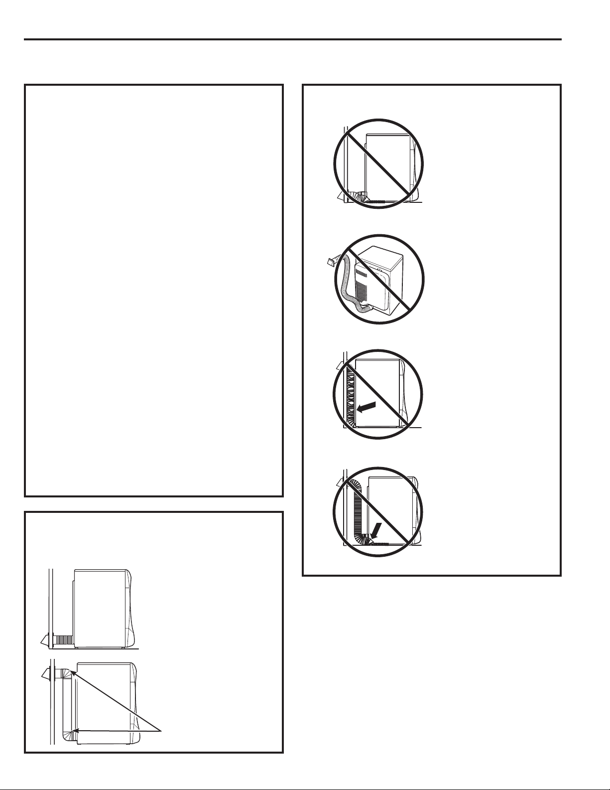
130
SALIDA AL EXTERIOR DE LA SECADORA (cont.)
Instrucciones de instalación
CÓMO UTILIZAR CONDUCTOS DE
METAL FLEXIBLES PARA VENTILACIÓN
DE TRANSICIÓN
Se recomiendan los conductos de metal rígidos o
semi-rígidos como conductos de transición entre
la secadora y la pared. En instalaciones especiales
donde resulta imposible efectuar una conexión con
las recomendaciones anteriores, entonces puede
utilizarse un conducto de transición de metal flexible
listado UL entre la secadora y la conexión de la pared
solamente. El uso de este tipo de conducto afectará
el tiempo de secado. Sólo deben utilizarse los
conductos flexibles del tipo de aluminio especialmente
identificados por el fabricante para poder ser usados
con el artefacto. En los Estados Unidos, el conducto
debe cumplir con las indicaciones para conductos
de transición en secadoras de ropa, tema 2158A.
Si resulta necesario un conducto de transición
de metal flexible, deben seguirse las siguientes
instrucciones:
•
Utilice la longitud más corta posible. La longitud
total del conducto de metal flexible no deberá
superar los 2.4 m.
•
Estire el conducto hasta su longitud máxima.
•
No lo aplaste o pliegue.
•
Nunca utilice un conducto de metal flexible
dentro de la pared o dentro de la secadora.
•
No coloque el conducto sobre objetos afilados.
•
La ventilación debe cumplir con los códigos
de edificación locales.
• CORTE el
conducto lo más
corto posible e
instálelo derecho
en la pared.
•
UTILICE codos
cuando hagan
falta curvas.
• NO doble o pliegue
los conductos. Utilice
codos si algunos
codos resultan
necesarios.
• NO aplaste
el conducto contra
la pared.
•
NO coloque
la secadora en
el conducto.
Codos
NO HAGA LO SIGUIENTE:
• NO utilice una
longitud de salida
excesiva. Corte
los conductos con
la longitud más corta
posible.
PARA VENTILACIÓN DE TRANSICIÓN
(SECADORA A PARED), HAGA LO
SIGUIENTE:
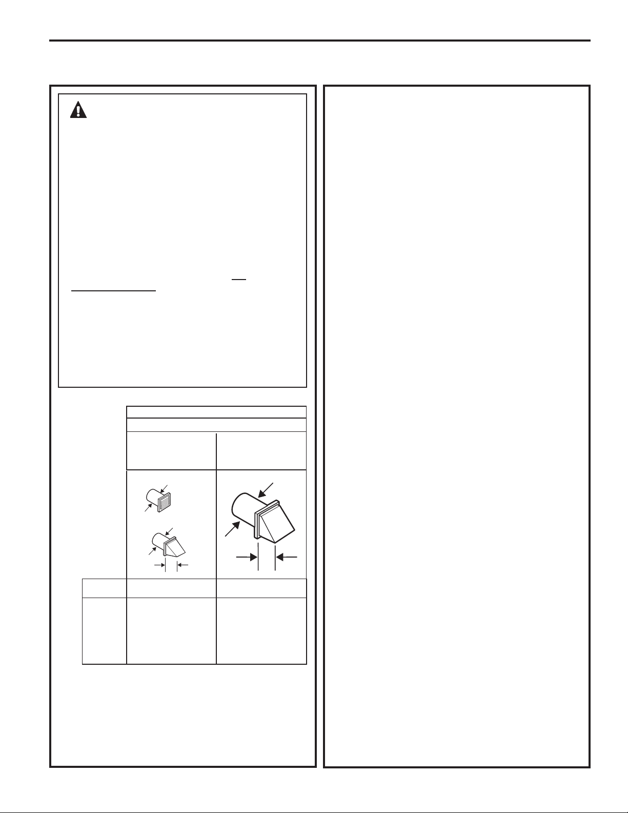
Instrucciones de instalación
LISTA DE CONTROL DEL SISTEMA DE
SALIDA
CAMPANA O CUBIERTA DE PARED
• Instale la salida de modo de evitar contracorrientes
o el ingreso de pájaros u otros insectos o animales.
• La boca de salida debe presentar una resistencia
mínima al flujo de salida y debe requerir poco
mantenimiento para evitar las obstrucciones.
• Nunca instale un filtro dentro o sobre el conducto
de salida. Esto podría provocar una acumulación
de pelusa.
• Las cubiertas de pared deben instalarse por lo
menos a 12” sobre el nivel del suelo o cualquier
otra obstrucción con la abertura apuntando
hacia abajo.
• Si se utilizan ventilaciones de techo o cámaras
con rejillas, éstos deben ser equivalentes a una
cubierta de pared con regulador de tiro de
4” en cuanto a corrientes de aire, prevención
de contracorrientes y mantenimiento requerido
para evitar obstrucciones.
SEPARACIÓN DE CURVAS
Para un mejor desempeño, separe todas las curvas
con 4 pies de conducto recto
como mínimo,
incluyendo la distancia entre la última curva y la
campana de salida.
GIROS QUE NO SON DE 90º
• Un giro de 45º o menos puede ignorarse.
• Dos giros de 45º deben tratarse como un giro de
90º.
• Todos los giros de más de 45º deben tratarse
como un giro de 90º.
SELLADO DE JUNTAS
• Todas las juntas deben estar bien selladas para
evitar pérdidas. El extremo macho de cada
sección de conducto debe apuntar en dirección
opuesta de la secadora.
• No arme la red de conductos con sujeciones que
se extiendan dentro del conducto. Funcionarán
como un punto de acumulación de pelusas.
• Las juntas de los conductos deben ser herméticas
al aire y a la humedad mediante la superposición
de juntas con cinta aislante.
• Los tramos horizontales deben tener una
inclinación hacia el exterior de 1/4” por pie.
AISLACIÓN
• Los conductos instalados a través de una área sin
calefacción o ubicados cerca de un acondicionador
de aire deben aislarse para reducir la condensación
y la acumulación de pelusas.
ADVERTENCIA – SÓLO USE
UN CONDUCTO DE METAL DE 4”. NO UTILICE
UN CONDUCTO DE UNA LONGITUD MAYOR A
LA ESPECIFICADA EN LA TABLA DE LONGITUD
DE SALIDA.
Al utilizar una salida de mayor longitud a la
especificada se:
• Incrementarán los tiempos de secado y el costo de
energía.
• Reducirá la vida útil de la secadora.
• Acumulará pelusa, lo que podría generar un riesgo
potencial de incendio.
La correcta instalación de salida es SU
RESPONSABILIDAD.
Los problemas generados por una instalación
incorrecta no se encuentran cubiertos por la
garantía.
La longitud MÁXIMA PERMITIDA del sistema de salida
depende del tipo de conducto, la cantidad de curvas,
la clase de campana de salida (cubierta de pared) y
todas las condiciones indicadas a continuación.
LONGITUD DE SALIDA
LONGITUD MÁXIMA RECOMENDADA
Tipos de campana de salida
Recomendado Utilizar sólo en
instalaciones de
trayecto corto
Cant. de Metal Metal
codos de 90º rígido rígido
0 150 pies 125 pies
1 135 pies 115 pies
2 125 pies 105 pies
3 115 pies 95 pies
4 105 pies 85 pies
5 95 pies 75 pies
4
”
2
1
ø
2
”
4
”
DIA
4
”
DIA
4
”
DIA
• Para cada codo adicional de 90°, reduzca en 10 pies la
longitud permisible del sistema de escape.
• Dos codos de 45° deberán ser considerados como un codo de 90°.
• Para el escape lateral, agregue un codo de 90° a la tabla.
• La longitud total del sistema de escape incluye todas las
porciones rectas y todos los codos del sistema (incluyendo
el ducto de transición).
131
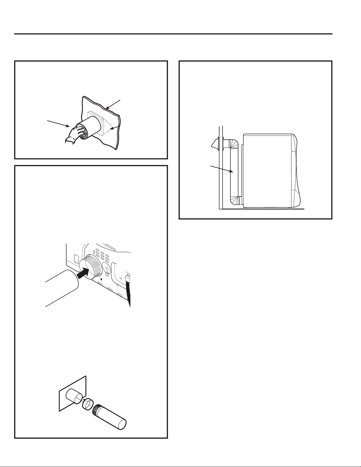
132
Instrucciones de instalación
ANTES DE COMENZAR
Quite las pelusas de la abertura de salida de la
pared.
Abertura de
conducto
interno
Pared
Verifique que el
regulador de tiro
de la campana de
salida se abra y
cierre libremente.
SALIDA TRASERA ESTÁNDAR
Recomendamos instalar la secadora antes que la
lavadora. Esto permitirá un acceso directo para
poder efectuar la conexión de salida.
Deslice el extremo del conducto de salida hacia
la parte trasera de la secadora y sujete con cinta
aislante o una abrazadera de mangueras.
NOTA: Recomendamos el uso de un conducto
de salida rígido de metal. Si utiliza un conducto
semi-rígido de metal, córtelo con la longitud
adecuada y trate de que no se aplaste detrás de la
secadora.
•
Para una instalación en línea recta, conecte
la salida de la secadora a la pared con cinta
aislante.
CONFIGURACIÓN RECOMENDADA PARA
MINIMIZAR LAS OBSTRUCCIONES DE LA
SALIDA
El uso de codos evitará que los conductos se
tuerzan y caigan.
Conducto
Conducto de
transición
Lado de la pared
Lado de la
secadora
SALIDA AL EXTERIOR DE LA SECADORA (cont.)
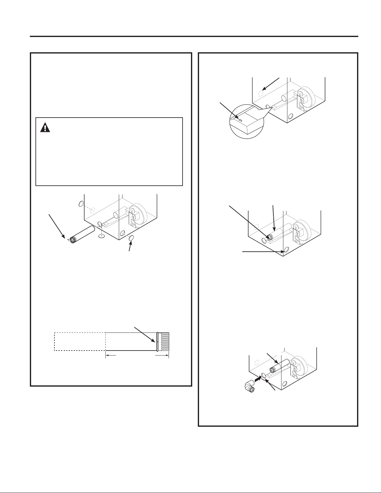
ADVERTENCIA:
ANTES DE EFECTUAR ESTA INSTALACIÓN DE
SALIDA, ASEGÚRESE DE DESCONECTAR LA
SECADORA DEL SUMINISTRO ELÉCTRICO.
PROTEJA SUS MANOS Y BRAZOS DE LOS LADOS
AFILADOS CUANDO TRABAJE DENTRO DEL
GABINETE. ASEGÚRESE DE USAR GUANTES.
Instrucciones de instalación
VENTILACIÓN LATERAL
La secadora cuenta con una salida hacia la derecha
del gabinete sólo en modelos eléctricos.
La secadora cuenta con una salida hacia la
izquierda del gabinete en modelos a gas y
eléctricos.
Despegue y quite la tapa inferior, derecha o
izquierda, según corresponda. Quite el tornillo
ubicado dentro del conducto de salida de la
secadora y consérvelo. Saque el conducto de la
secadora.
Quite el
tornillo y
consérvelo
Quite la tapa
deseada (sólo una)
Orificio de montaje
Corte el conducto como puede verse y conserve la
porción A.
CÓMO AGREGAR UN CONDUCTO NUEVO
Vuelva a conectar la porción cortada “A” del conducto
a la caja del ventilador. Asegúrese de que el conducto
más corto se encuentre alineado con la lengüeta de
la base. Utilice el tornillo conservado con anterioridad
para sujetar el conducto en su lugar a través de la
lengüeta de la base del artefacto.
CÓMO AGREGAR CODOS Y CONDUCTOS DE
SALIDA HACIA LA IZQUIERDA O DERECHA
DEL GABINETE
•
Introduzca el codo de 4” a través de la abertura trasera
y conéctelo al conducto interno de la secadora.
Porción “A”
Salida del lado
izquierdo
Orificio de montaje
UBICACIÓN DE LA LENGÜETA
Gire la lengüeta
hasta 45°
A través de la abertura trasera, ubique la lengüeta
en el medio de la base del artefacto. Levante la
lengüeta hasta alrededor de 45°, utilizando un
destornillador de lados planos.
No para gas
A
13
1
ø2” 34.3 cm
Derecha
Izquierda
Parte inferior
Conducto interno
Abertura trasera
133
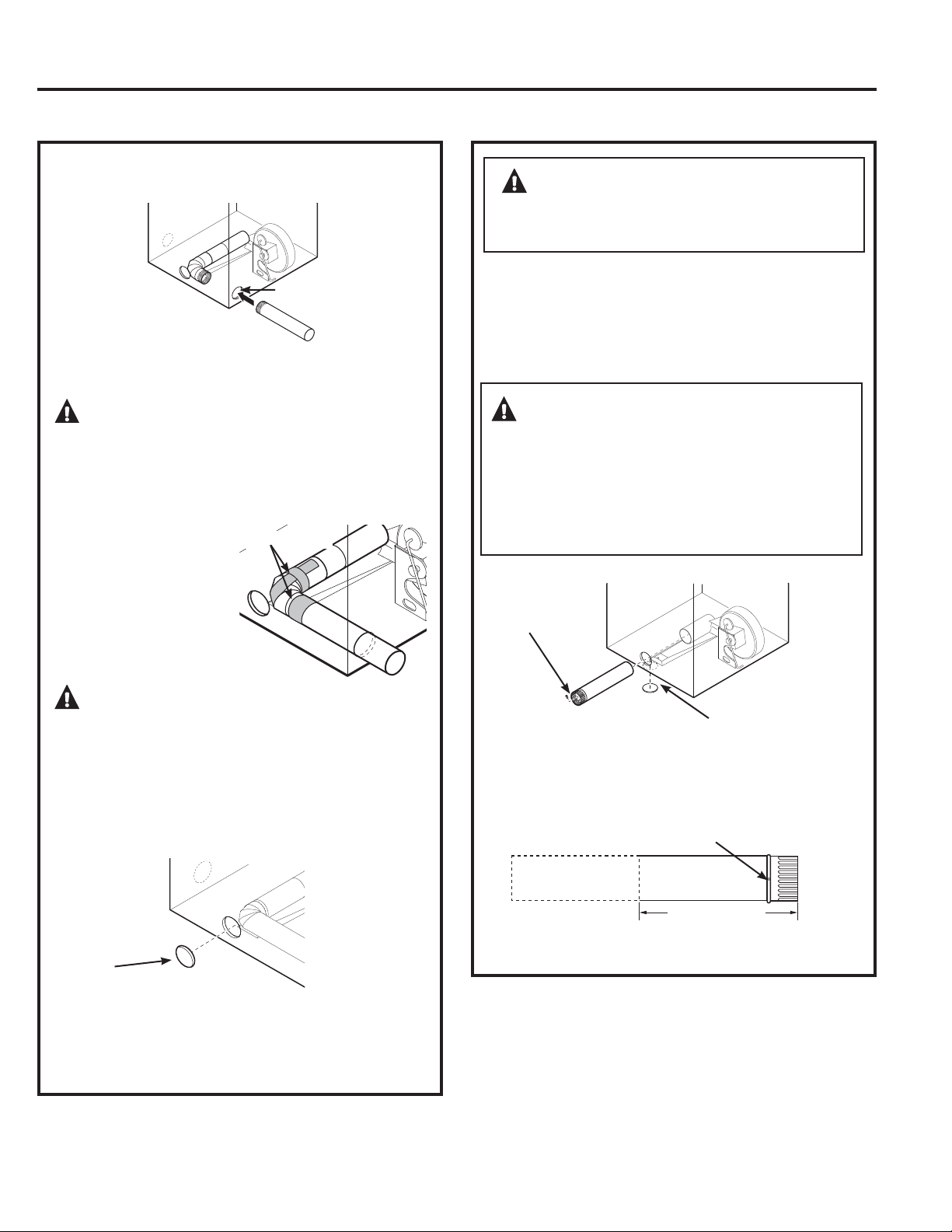
134
Instrucciones de instalación
VENTILACIÓN LATERAL (cont.)
Conecte los codos y conductos de metal estándar
para completar el sistema de salida. Cubra la abertura
trasera con la placa (Kit WE1M454), disponible en su
proveedor de servicios local. Coloque la secadora en
su ubicación final.
Placa (Kit
WE1M454)
Abertura lateral
• Aplique cinta aislante
como puede verse en la
junta entre el conducto
interno de la secadora y
el codo, y también en la
junta entre el codo y el
conducto lateral.
PRECAUCIÓN: Las juntas del
conducto interno deben sujetarse con cinta; caso
contrario, pueden separarse y provocar un riesgo de
seguridad.
Cinta aislante
ADVERTENCIA: NUNCA DEJE
LA ABERTURA TRASERA SIN LA PLACA EN SU
LUGAR.
(Kit WE1M454)
CÓMO AGREGAR LA PLACA DE CUBIERTA A
LA PARTE TRASERA DEL GABINETE (SALIDA
LATERAL)
• Introduzca el conducto de 4” a través de la
abertura lateral y conéctelo al codo.
PRECAUCIÓN: UTILICE UN
CONDUCTO DE METAL RÍGIDO DE 4” SÓLO DENTRO
DE LA SECADORA. LAS JUNTAS DEL CONDUCTO
INTERNO DEBEN SUJETARSE CON CINTA; CASO
CONTRARIO, PUEDEN SEPARARSE Y PROVOCAR UN
RIESGO DE SEGURIDAD.
ADVERTENCIA:
ANTES DE EFECTUAR ESTA INSTALACIÓN DE
SALIDA, ASEGÚRESE DE DESCONECTAR LA
SECADORA DEL SUMINISTRO ELÉCTRICO.
PROTEJA SUS MANOS Y BRAZOS DE LOS LADOS
AFILADOS CUANDO TRABAJE DENTRO DEL
GABINETE. ASEGÚRESE DE USAR GUANTES.
VENTILACIÓN POR LA PARTE INFERIOR
La secadora cuenta con una salida por la
parte inferior del gabinete en modelos a gas y
eléctricos.
Quite el tornillo ubicado dentro del conducto de salida
de la secadora y consérvelo. Saque el conducto de la
secadora. Desconecte y quite la tapa inferior.
Quite el
tornillo y
consérvelo
Quite la tapa
deseada (sólo una)
Orificio de montaje
Corte el conducto como puede verse y conserve
la porción A.
A
13
1
ø4” 33.7 cm
Parte
inferior
SALIDA AL EXTERIOR DE LA SECADORA (cont.)
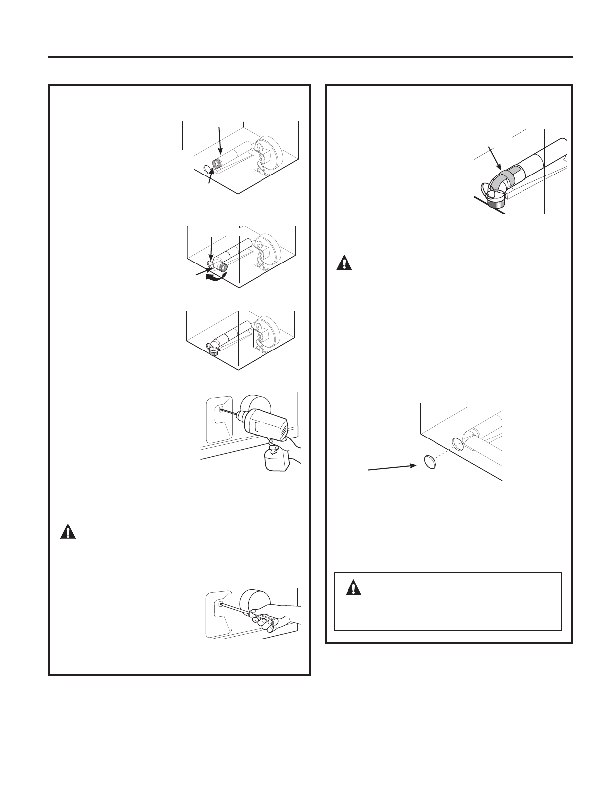
ADVERTENCIA: NUNCA
DEJE LA ABERTURA TRASERA SIN LA PLACA
EN SU LUGAR.
(Kit WE1M454)
VENTILACIÓN POR LA PARTE
INFERIOR (cont.)
• Aplique cinta aislante
como puede verse en la
junta entre el conducto
interno de la secadora y el
codo.
NOTA: Asegúrese de que
la cinta cubra el orificio del
tornillo de la porción A donde se conecta con el
codo.
PRECAUCIÓN: Las juntas del
conducto interno deben sujetarse con cinta;
caso contrario, pueden separarse y provocar un
riesgo de seguridad.
La secadora cuenta con una salida por la
parte inferior del gabinete en modelos a gas
y eléctricos.
Conecte los codos y conductos de metal estándar
para completar el sistema de salida. Cubra la
abertura trasera con la placa (Kit WE1M454),
disponible en su proveedor de servicios local.
Coloque la secadora en su ubicación final.
Placa
(Kit WE1M454)
Instrucciones de instalación
Cinta
aislante
CÓMO AGREGAR LA PLACA DE CUBIERTA A
LA PARTE TRASERA DEL GABINETE (SALIDA
POR LA PARTE INFERIOR)
CÓMO AGREGAR UN CONDUCTO NUEVO
• Vuelva a conectar la
porción cortada “A” del
conducto a la caja del
ventilador.
•
Sujete el codo con
cinta en una posición
de 90 grados para
evitar la rotación.
•
Introduzca el codo
a través del orificio
trasero y conéctelo
a la porción “A”. Gire
el codo a través de la
abertura inferior.
•
Mientras sostiene
la tubería y codo,
utilizando su mano a
través de la abertura
trasera, perfore
un orificio de 1/8” a
través del orificio de
la lengüeta inferior y
la tubería como puede
verse en la ilustración.
NOTA: Asegúrese de que el orificio atraviese bien el
codo y la tubería.
PRECAUCIÓN: Asegúrese de no
tirar o dañar los cables eléctricos ubicados dentro
de la secadora cuando introduzca el conducto.
•
Mientras todavía
sostiene la tubería y
codo de la abertura
trasera, atornille las
tuberías en su lugar con
el tornillo conservado
con anterioridad.
Abertura
de la parte
inferior
Visión inferior
Porción “A”
Orificio de
montaje
Orificio trasero
135
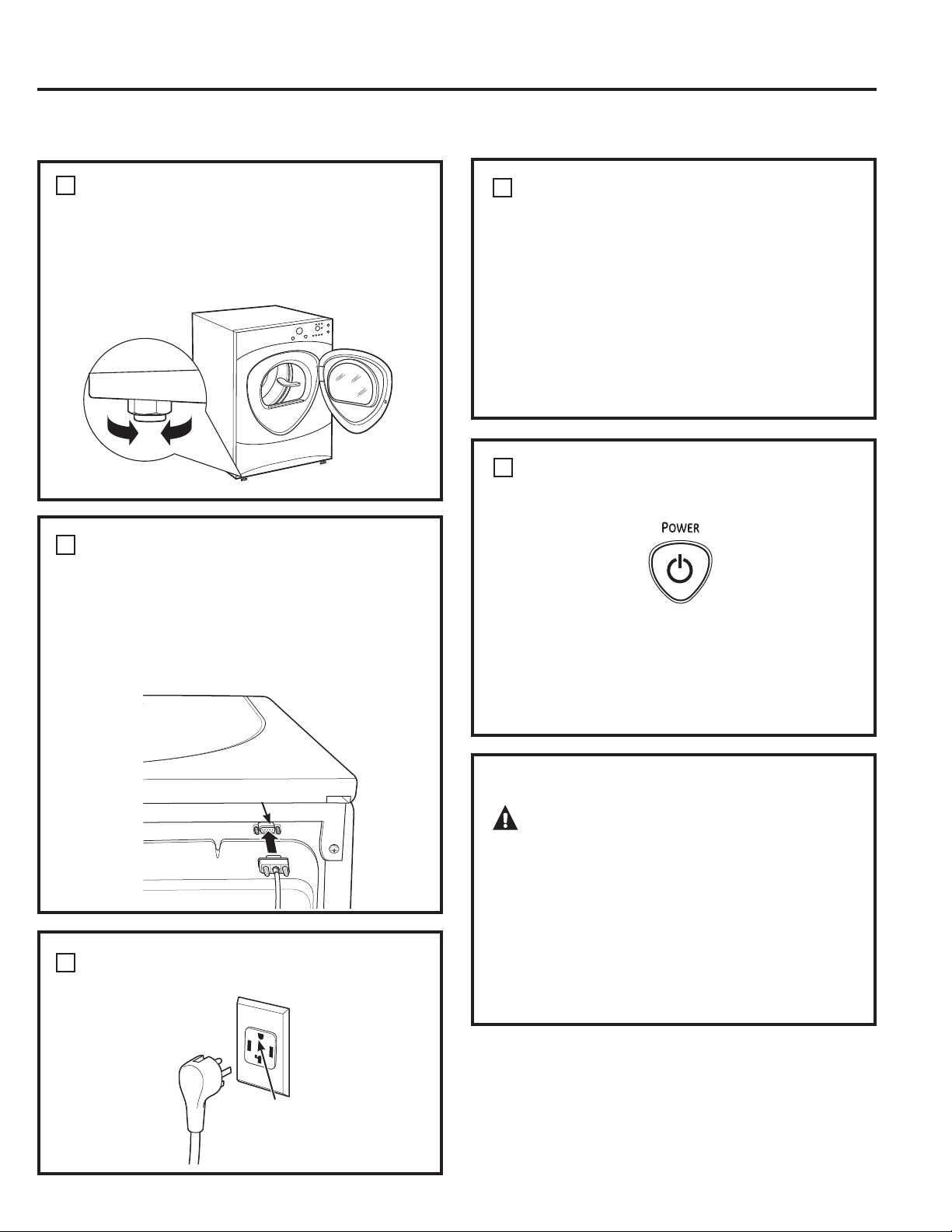
136
Instrucciones de instalación
NIVELE LA SECADORA
Coloque la secadora en posición vertical cerca de
la ubicación definitiva y ajuste las cuatro patas
niveladoras para garantizar que la secadora se
encuentre nivelada de lado a lado y del frente a la
parte trasera.
Bajar
Elevar
CONECTE EL CABLE SERIAL
Sujete el cable serial de la conexión de lavadora y
secadora al puerto serial ubicado en la parte trasera
de la secadora.
Conecte el otro extremo del cable a la lavadora antes
de colocar la lavadora en su posición definitiva.
ENCHUFE LA SECADORA
Verifique que haya
una conexión a tierra
adecuada antes del uso.
Parte
trasera de
la lavadora
1
2
CONFIGURACIÓN FINAL
3
Puerto serial
INICIO DE LA SECADORA
Presione el botón POWER (encendido).
NOTA: Si la secadora ha sido expuesta a temperaturas
bajo cero por un período prolongado, deje que suba
la temperatura antes de presionar POWER. De otra
manera, la pantalla no se encenderá.
Su secadora ya está lista para usar.
REPARACIÓN
ADVERTENCIA:
Etiquete todos los cables antes de la desconexión
cuando haga reparaciones de los controles.
Los errores de cableado pueden provocar un
funcionamiento inadecuado y peligroso después
de la reparación/instalación.
Para piezas de repuesto y otra información, diríjase
a la página 151 para obtener números telefónicos
de servicio.
4
INSTRUCCIONES DE CONEXIÓN A TIERRA
Este electrodoméstico se debe conectar a tierra. En
caso de mal funcionamiento o avería, la conexión
a tierra reducirá el riesgo de descarga eléctrica,
al brindar un camino de menor resistencia para la
corriente eléctrica. El electrodoméstico se encuentra
equipado con un cable que posee un equipo de
conducción a tierra y un enchufe de conexión a tierra.
El enchufe se debe colocar en un tomacorriente
instalado de forma adecuada y se deberá conectar a
tierra de acuerdo con todos los códigos y ordenanzas
locales.
4
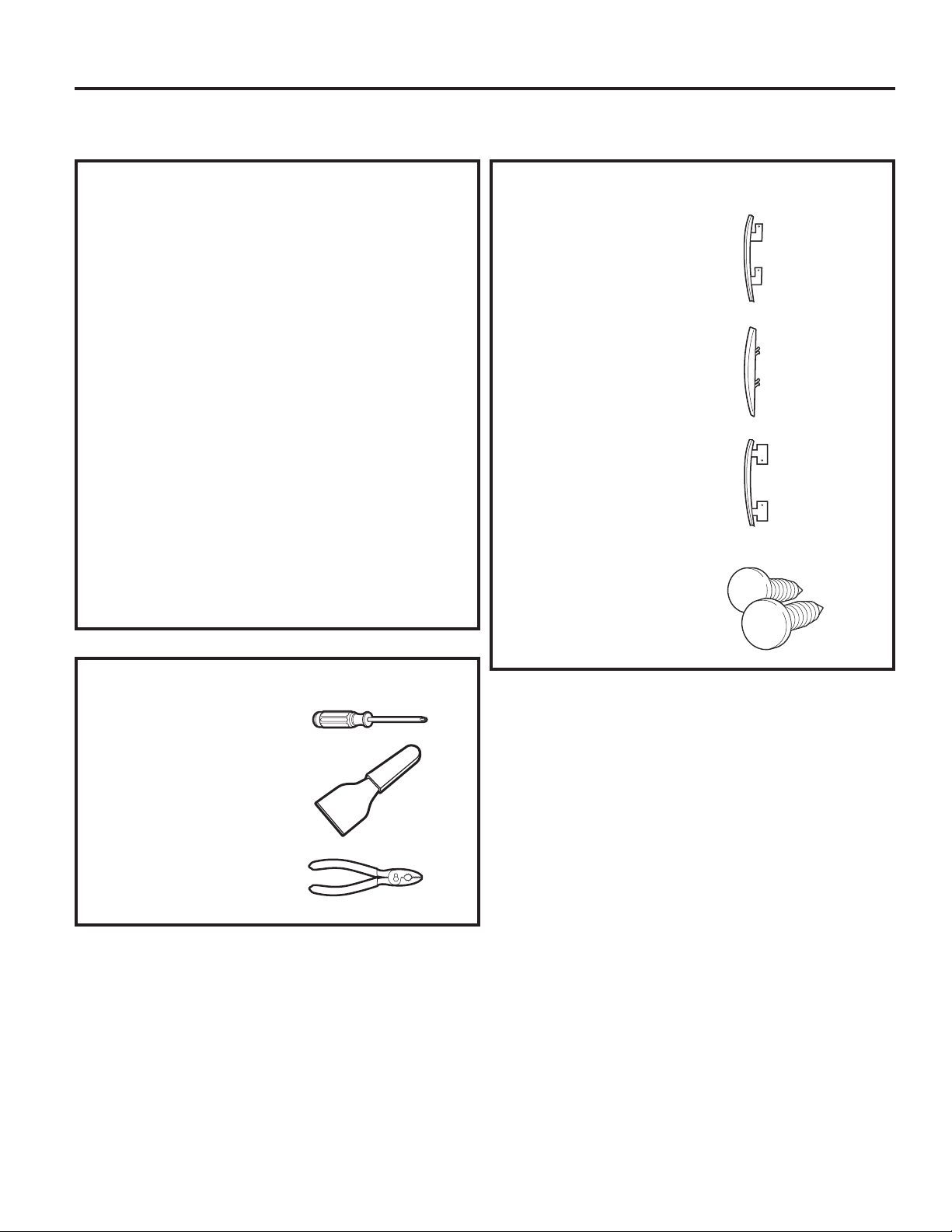
Instrucciones de instalación
CÓMO INVERTIR LA APERTURA DE LA PUERTA (si así se desea)
NOTAS IMPORTANTES
• Lea todas las instrucciones antes de comenzar.
• Manipule las piezas con cuidado para no rayar la
pintura.
• Coloque las puertas sobre una superficie de
trabajo que no raye.
• Separe los tornillos por sus piezas relacionadas
para evitar usarlos en lugares equivocados.
• Todos los tornillos deben ajustarse a mano.
• El tiempo normal utilizado para invertir la apertura
de la puerta es de 30–60 minutos.
IMPORTANTE: Una vez que haya comenzado,
no mueva el gabinete hasta haber finalizado la
inversión de la apertura de la puerta.
Estas instrucciones son para cambiar las bisagras
del lado derecho al lado izquierdo; si alguna vez
desea cambiarlas de nuevo al lado derecho, siga
las mismas instrucciones e invierta todas las
referencias de izquierda a derecha.
HERRAMIENTAS NECESARIAS
KIT ESTÁNDAR DE REVERSIBILIDAD
Tapa de puerta de cromo
Tapa de bisagra de puerta de
cromo
Tapa de puerta interna
2 botones obturadores
Destornillador Phillips o
destornillador quadrex
Espátula o destornillador de
lados finos
Pinzas
137
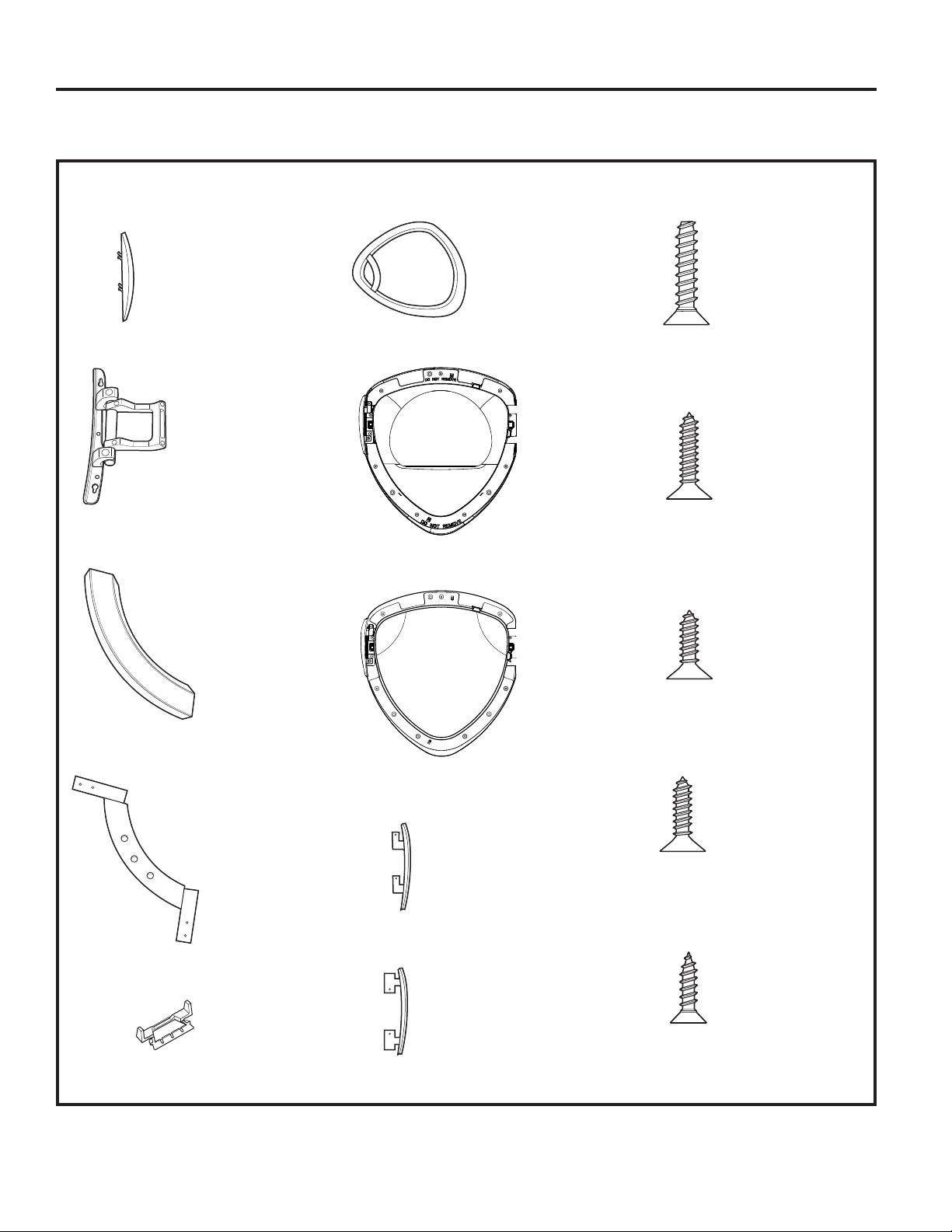
138
CÓMO INVERTIR LA APERTURA DE LA PUERTA (si así se desea)
PIEZAS DE LA PUERTA
Tapa de la bisagra
Montaje de bisagra
Manija exterior
Manija interior
2 tapas de la manija
Cubierta de puerta de cromo
Cubierta interior (máscara)
Ventana exterior
Tapa de puerta de cromo
Tapa de puerta interna
A Tornillos auto-roscantes
grandes
7 – #10 x 1.125”
B Tornillos auto-roscantes
grandes
2 – #10 x 0.750”
C Tornillo auto-roscante
pequeño
1 – #8 x 0.375”
D Tornillos auto-roscantes
pequeños
11 – #8 x 0.625”
E Tornillos mecánicos
4 – #8 x 0.50”
Instrucciones de instalación
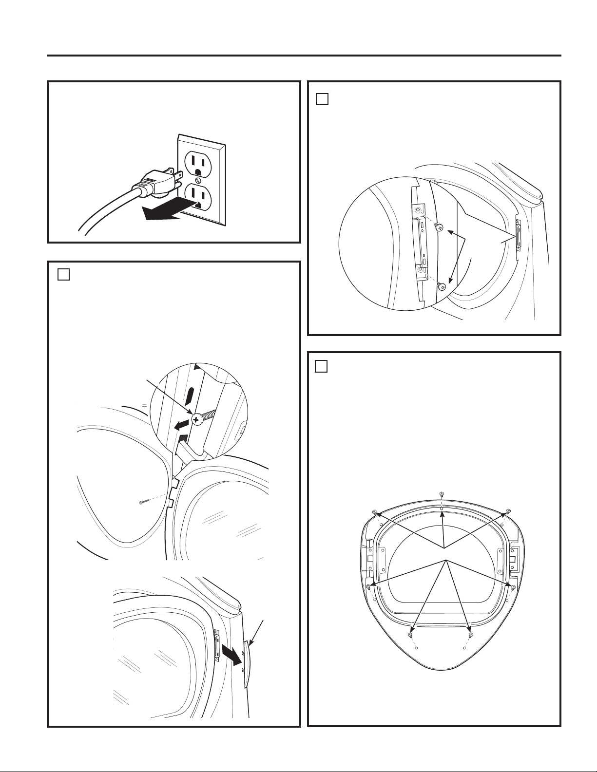
QUITE EL MONTAJE DE LA PUERTA
Quite la tapa de la bisagra lateral abriendo la
puerta de la secadora y quitando el tornillo de la
parte trasera de la bisagra (tornillo auto-roscante
#8 x .375”). Luego, usando la mano, quite la tapa de
la bisagra de la secadora.
Tapa
de la
bisagra
1
DESARME EL MONTAJE DE LA
PUERTA
Coloque la puerta sobre una superficie plana,
suave y protegida de modo que la parte interior
mire hacia arriba (la puerta descansa sobre el lado
de la manija).
Quite los 7 tornillos (tornillos auto-roscantes #10
x 1.125”) ubicados alrededor del perímetro de la
puerta.
2
Dé vuelta el montaje de la puerta y separe la tapa
de cromo de la puerta interior. Coloque la puerta
interior en una superficie plana, suave y protegida.
7 x A Tornillos
Instrucciones de instalación
ANTES DE COMENZAR
Desenchufe la secadora del tomacorriente.
QUITE EL MONTAJE DE LA PUERTA (cont.)
1
Cierre y sostenga la puerta, quite los 2 tornillos de
la bisagra (tornillos auto-roscantes #10 x 0.75”).
Aleje la puerta del panel frontal de la secadora.
2 x B
Tornillos
1 x C Tornillos
139
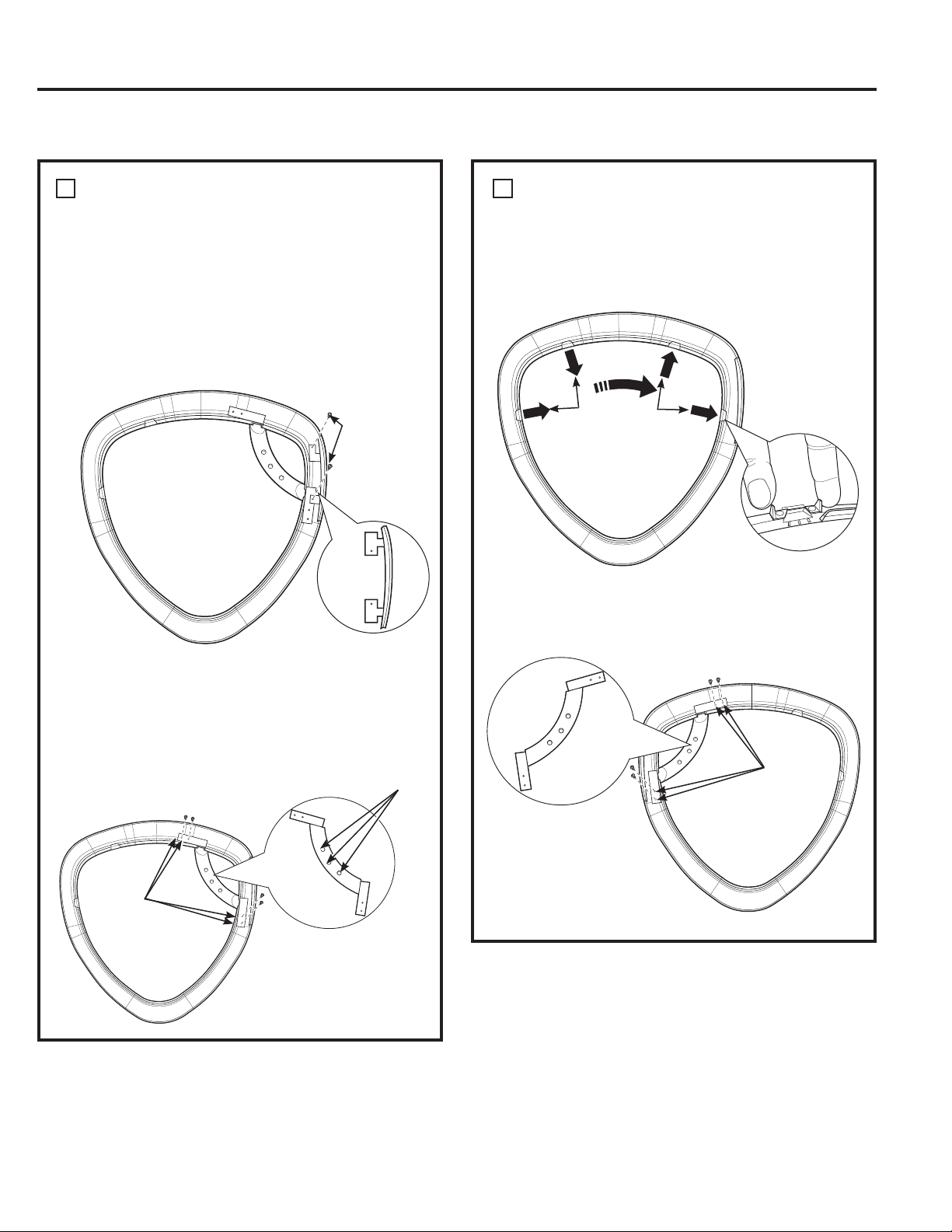
140
CÓMO INVERTIR LA APERTURA DE LA PUERTA (si así se desea)
Instrucciones de instalación
CÓMO INVERTIR LA MANIJA Y LAS
TAPAS DE LA PUERTA
3
CÓMO INVERTIR LA MANIJA Y LAS
TAPAS DE LA PUERTA
C Quite las 2 tapas de la manija y vuelva a armar
en el lado opuesto de la cubierta de cromo,
donde se quitó la manija exterior.
3
B Desarme la manija exterior de la manija interior
quitando 3 tornillos (tornillos auto-roscantes
#8 x 0.625”) Desarme la manija interior de la
cubierta de cromo quitando 4 tornillos (tornillos
auto-roscantes #8 x 0.625”).
D Coloque la manija interior en el lado opuesto
de la cubierta de cromo utilizando 4 tornillos
(tornillos auto-roscantes #8 x 0.625”).
Tapa
de la
puerta
2 x D Tornillos
Quite
4 x D tornillos
(Manija interior)
Manija
interior
3 x D Tornillos
(manija exterior)
Tapas de la
manija
Vuelva a
colocar
4 x D
tornillos
(manija
interior)
Manija
interior
A Coloque la cubierta de cromo sobre una superficie
plana, suave y protegida de modo que la parte
interior mire hacia arriba (apoyada sobre el lado
de la manija). Desarme la tapa de la puerta de la
cubierta de cromo del lado de la manija quitando
2 tornillos (tornillos auto-roscantes #8 x 0.625”).
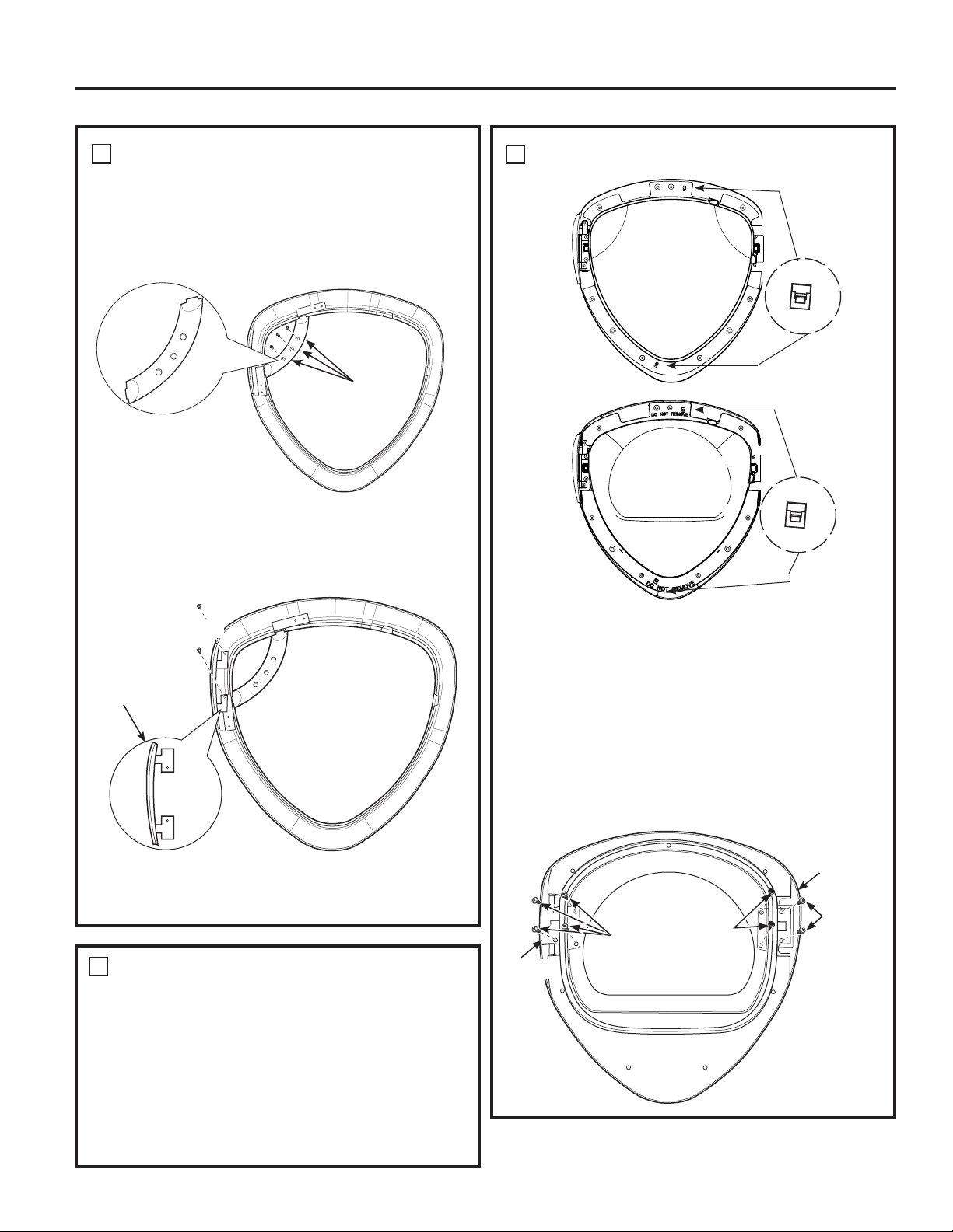
CÓMO INVERTIR LA MANIJA Y LAS
TAPAS DE LA PUERTA (CONT.)
Coloque la cubierta de cromo en una superficie
plana, suave y protegida.
F Arme la nueva tapa de la puerta del lado
derecho (del kit de reversibilidad), utilizando 2
tornillos (tornillos auto-roscantes #8 x 0.625”).
CÓMO INVERTIR LAS BISAGRAS Y TAPAS
4
• Gire la puerta interior sobre una superficie plana,
suave y protegida de modo que la parte interior
mire hacia arriba.
•
Quite los tornillos, tuercas y arandelas del lado opuesto
de la bisagra utilizando un destornillador quadrex.
•
Arme la nueva tapa de la puerta interna (del kit de
reversibilidad) sobre el lado opuesto de la bisagra,
utilizando 2 tornillos (tornillos auto-roscantes #8 x 0.75”).
• Coloque la bisagra en el lado opuesto de la
puerta interna utilizando 4 tornillos (tornillos
mecánicos #8-32 x 0.50”).
Instrucciones de instalación
E Vuelva a armar la manija externa de la cubierta
de cromo, utilizando 3 tornillos (tornillos auto-
roscantes #8 x 0.625”).
3 x D
Tornillos
(manija
interna)
Tapa de la
puerta
2 x D Tornillos
Manija
exterior
CÓMO INVERTIR LAS BISAGRAS Y TAPAS
• Coloque la puerta interior sobre una superficie
plana, suave y protegida de modo que la parte
interior mire hacia abajo. Desarme la ventana
exterior abriendo 2 trabas, coloque la ventana
exterior sobre una superficie plana, suave y
protegida.
• Desarme la cubierta interior (máscara) abriendo 2
trabas, coloque la cubierta interior (máscara) sobre
una superficie plana, suave y protegida.
Ventana exterior
Cubierta
interior
(máscara)
Traba
Traba
Bisagra
Quite
4 x E
tornillos
2 x D
Tornillos
Tapa de
puerta
interna
2 tornillos,
2 tuercas y
2 arandelas
4
3
141
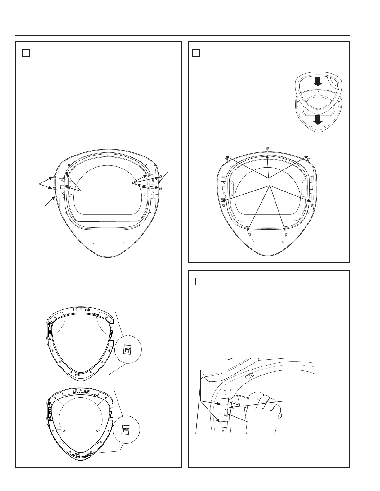
142
CÓMO VOLVER A COLOCAR EL
MONTAJE DE LA PUERTA
Dé vuelta la puerta interior y
colóquela sobre una superficie
plana, suave y protegida de modo
que la parte interior mire hacia
abajo. Sujete la cubierta de cromo
a la puerta interior colocándolas
juntas. Dé vuelta el montaje de
la puerta y ármelo utilizando 7
tornillos (tornillos auto-roscantes
#10 x 1.125”).
5
7 x A Tornillos
CÓMO INVERTIR LOS BOTONES
OBTURADORES DEL PANEL FRONTAL
Y LA PLACA DE CERRADO
6
Quite los 2 botones obturadores del panel frontal de la
secadora utilizando una espátula u otra herramienta
plana como se muestra y vuelva a instalarlos en el lado
opuesto. Cambie el soporte de cerrado y su cubierta
quitando 2 tornillos (tornillos auto-roscantes #8 x 0.625”)
en cada uno y reinstalándolos en lados opuestos.
NOTA: Aplique un trozo de cinta protectora al costado
del botón obturador donde se introducirá la hoja de la
espátula para evitar rayones.
Soporte
de cerrado
2 botones
obturadores
Trozo de cinta
protectora
Instrucciones de instalación
CÓMO INVERTIR LA MANIJA Y LAS
TAPAS DE LA PUERTA (CONT.)
4
• Coloque la bisagra en el lado opuesto de la puerta
interna utilizando 4 tornillos (tornillos mecánicos
#8-32 x 0.50”).
•
Arme la nueva tapa de la puerta interna (del kit de
reversibilidad) sobre el lado opuesto de la bisagra,
utilizando 2 tornillos (tornillos auto-roscantes #8 x 0.75”).
• Instale los tornillos, tuercas y arandelas sobre
el lado opuesto de la bisagra en los 2 orificios
restantes.
Vuelva a
colocar
2 x D
tornillos
Bisagra
Vuelva a
colocar
4 x E
tornillos
Tapa
de puerta
interna
Vuelva a
colocar los
2 tornillos,
2 tuercas y
2 arandelas
Ventana exterior
Cubierta
interior
(máscara)
Traba
Traba
• Dé vuelta la puerta interior para que la parte
interior se dirija hacia abajo. Arma la cubierta
interior (máscara) y asegúrese de que las trabas
se hayan fijado a la cubierta interior. Arma la
ventana exterior y asegúrese de que las 2 trabas
se hayan fijado a la ventana exterior.
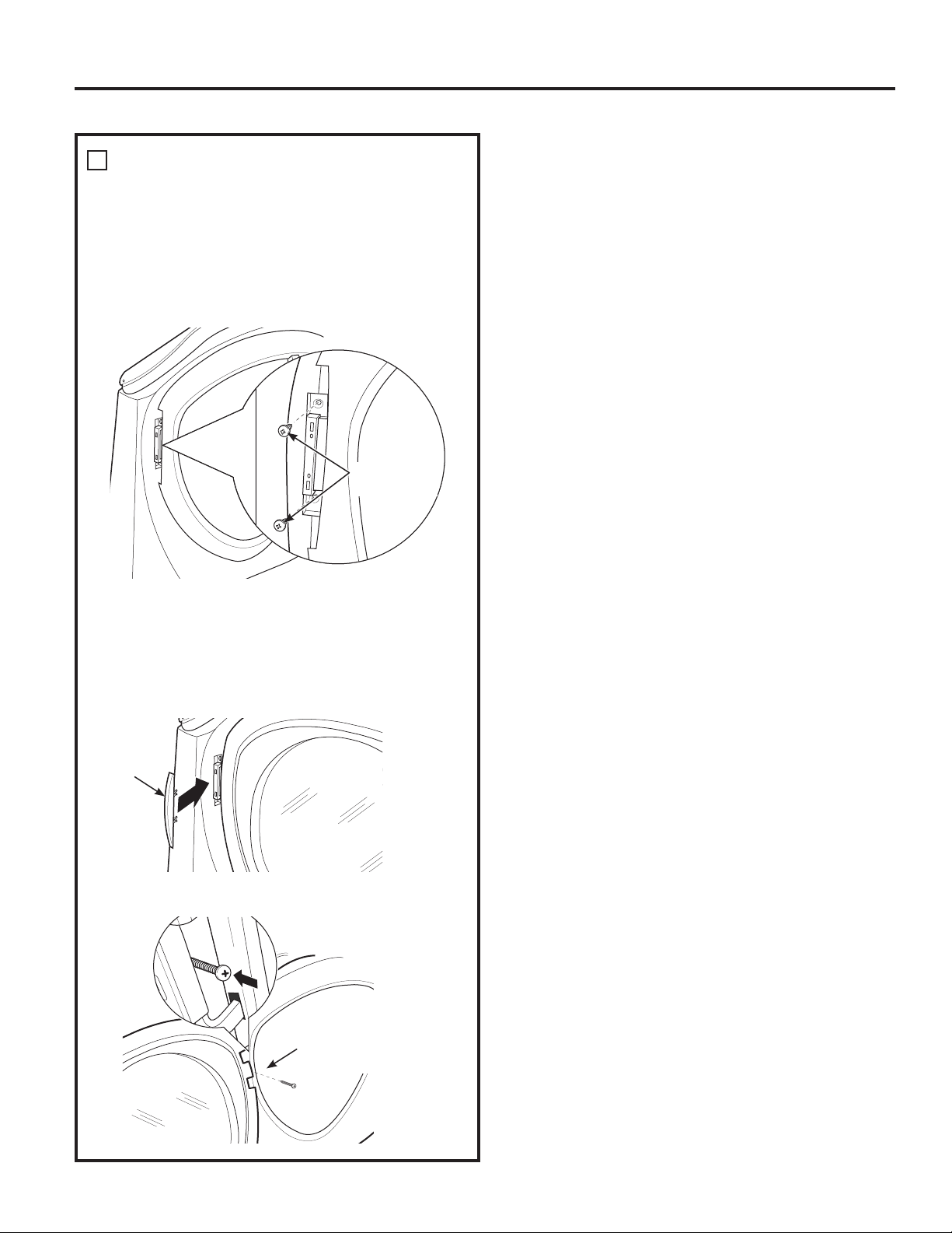
Instrucciones de instalación
CÓMO REINSTALAR EL MONTAJE DE
LA PUERTA
7
Instale la nueva tapa de la bisagra de la izquierda
(del kit de reversibilidad) en la bisagra abriendo la
puerta de la secadora y atornillando la tapa de la
bisagra en su lugar.
NOTA: Conserve las tapas y cubiertas sobrantes por
si alguna vez quiere volver a invertir la bisagra.
Instale 2 x B
los tornillos
Coloque la puerta en el panel frontal de la secadora,
verificando que la traba esté activada y que la
bisagra se encuentre ubicada en las dos aberturas
del frente de la secadora. Sujete la puerta al
gabinete frontal utilizando 2 tornillos (tornillos auto-
roscantes #10 x 0.75”).
1 x C Tornillos
en tapa de la bisagra
Tapa de
la bisagra
CÓMO INVERTIR LA APERTURA DE LA PUERTA (si así se desea)
143
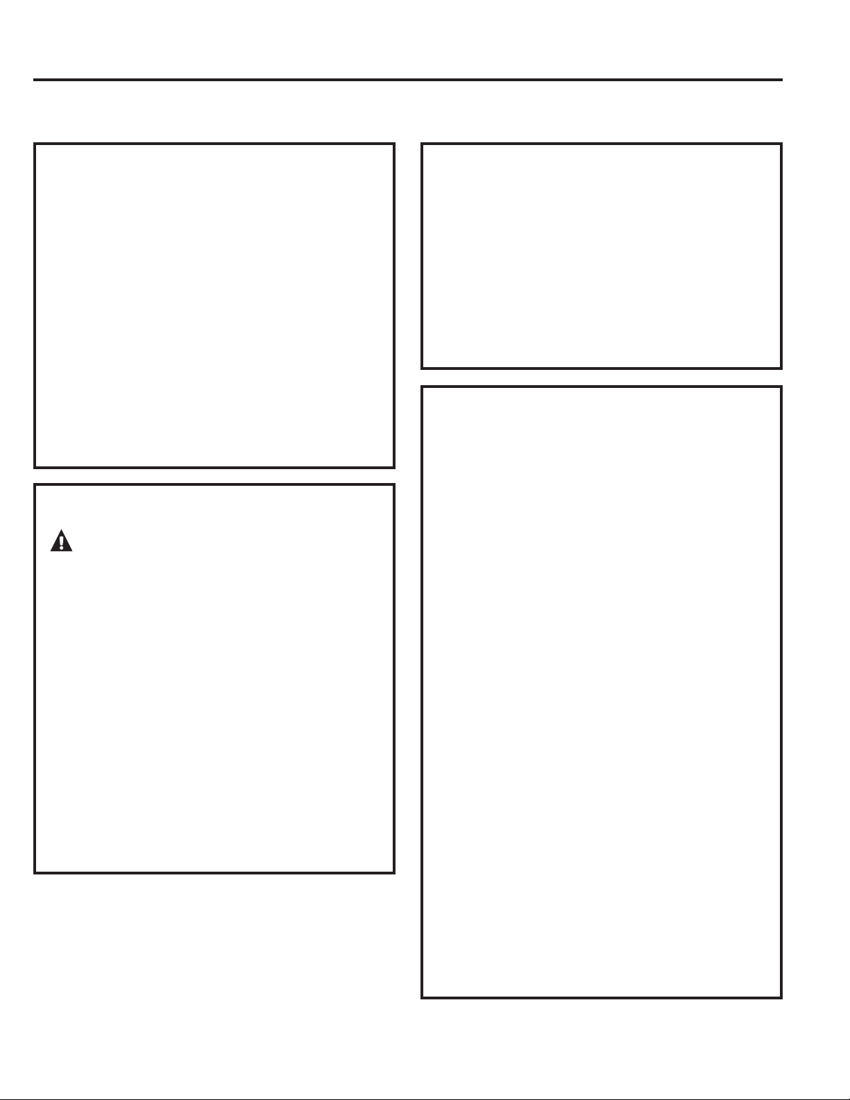
144
CÓMO APILAR LA LAVADORA Y LA SECADORA (si así lo desea)
ANTES DE COMENZAR
Lea detenidamente todas las instrucciones.
•
IMPORTANTE – Guarde estas
instrucciones para uso del inspector local.
•
IMPORTANTE – Cumpla todos los
códigos y ordenanzas regulatorias.
• Nota al instalador – Asegúrese de dejar estas
instrucciones al usuario.
• Nota al usuario – Guarde estas instrucciones
para consultas futuras.
• La instalación debe efectuarla un instalador
calificado.
• La instalación adecuada es responsabilidad del
instalador.
PARA SU SEGURIDAD:
ADVERTENCIA:
• Peligro de descarga eléctrica. Desconecte la
energía antes de instalar. No hacerlo puede
provocar una lesión personal grave o la muerte.
• Lesiones personales potenciales. Se recomienda
que más de dos personas levanten la secadora
hasta su posición debido a su peso y tamaño.
No hacerlo puede provocar una lesión personal
o la muerte.
• Evite la inclinación y ruptura de los servicios
públicos. La secadora debe estar bien sujeta
a la lavadora. NO coloque la lavadora sobre la
secadora. Hacerlo puede provocar una lesión
personal/la muerte o daños a la propiedad.
• Instalación en casas rodantes o casas
prefabricadas – No se permite apilar una secadora
a gas en casas rodantes o casas prefabricadas.
ESPACIO LIBRE MÍNIMO EN
OTROS ESPACIOS QUE NO SEAN
INSTALACIONES EN NICHOS O
ARMARIOS
Los espacios libres mínimos respecto de superficies
combustibles y de aberturas de aire son: 0” a ambos
lados, 1” en el frente y 3” en la parte trasera. Debe
tenerse en cuenta un espacio libre adecuado para
un funcionamiento y reparación correctos.
REQUERIMIENTOS PARA INSTALACIÓN
EN NICHOS O ARMARIOS
• Su secadora puede instalarse en un nicho o
armario, como se indica en la etiqueta de la parte
trasera del aparato.
•
Esta secadora DEBE tener una ventilación al
exterior. Ver la sección SALIDA AL EXTERIOR DE LA
SECADORA.
•
El espacio libre mínimo entre el armario de
la secadora y las paredes adyacentes u otras
superficies es:
0” sobre ambos lados
3” sobre el frente y la parte trasera
•
El espacio vertical mínimo desde el piso a sos,
etc., es de 52”.
•
Las puertas del armario deben contar con rejillas
u otro tipo de ventilación y tener por lo menos
60 pulgadas cuadradas de espacio abierto
igualmente distribuido. Si el armario incluye una
lavadora y una secadora, las puertas deben
contener un mínimo de 120 pulgadas cuadradas
de espacio abierto distribuido uniformemente.
•
El armario debe tener ventilación hacia el exterior
para evitar la acumulación de gas en caso de que
haya gas en la línea de suministro.
•
No deberán instalarse otros artefactos a
combustible en el mismo armario con la secadora
(sólo modelos a gas).
NOTA: CUANDO EL CONDUCTO DE SALIDA ESTÁ
UBICADO EN LA PARTE TRASERA DE LA SECADORA,
EL ESPACIO LIBRE MÍNIMO DESDE LA PARED DEBE
SER 5.5 PULGADAS.
Instrucciones de instalación
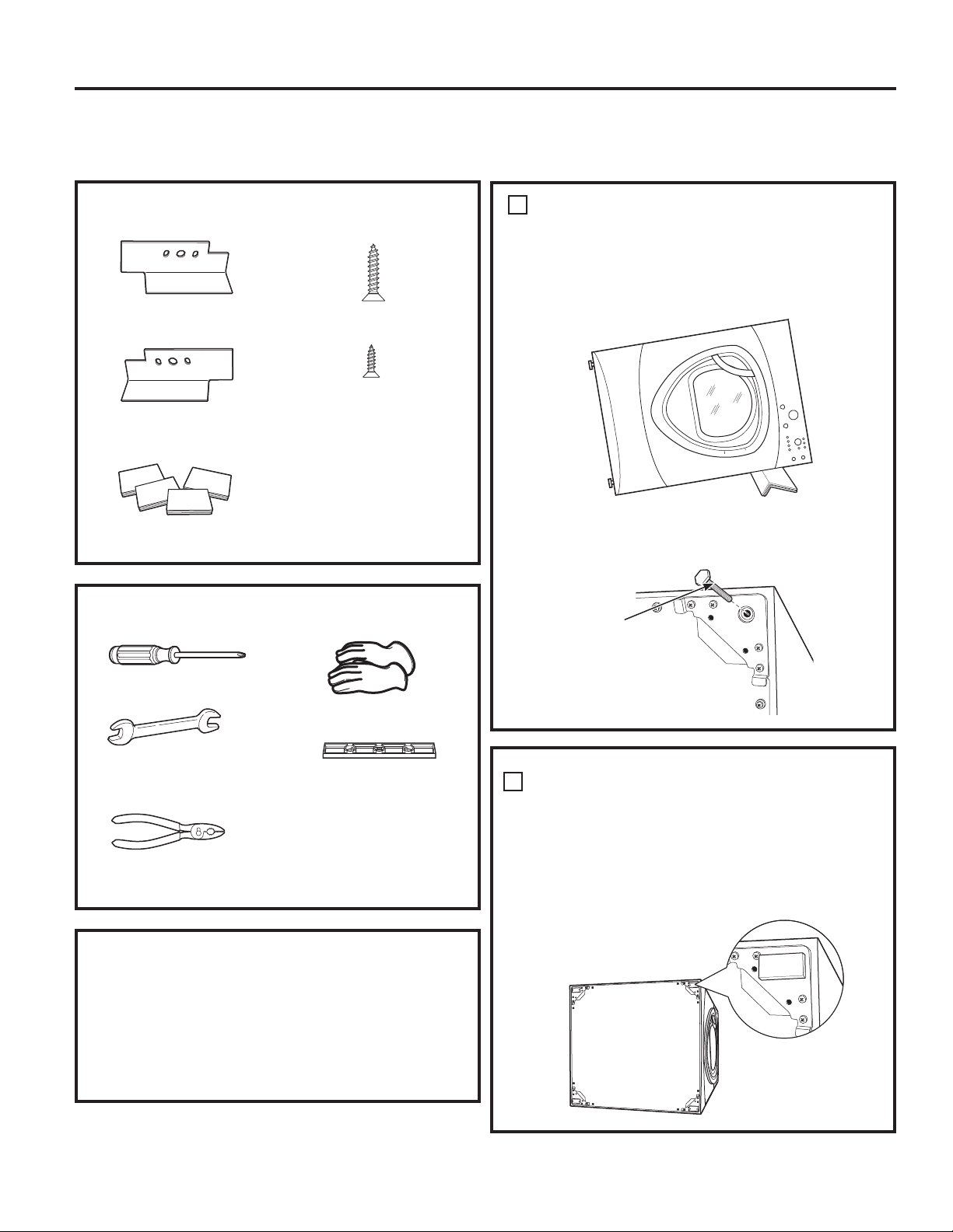
Destornillador Phillips
Llave de extremo abierto
Pinzas
Guantes
Nivel
CÓMO APILAR LA LAVADORA Y LA
SECADORA (si así lo desea) (cont.)
Instrucciones de instalación
PREPARACIÓN PARA LA INSTALACIÓN
Quite el envoltorio.
Aplaste el cartón del producto para poder utilizarlo
para colocar la secadora de costado. Siga usando
el cartón para proteger el piso frente al lugar de
instalación.
CONTENIDOS DEL KIT GE FL STACK
Soporte de lado
derecho
Soporte de lado
izquierdo
4 almohadillas de goma
4 tornillos #12 x 1”
4 tornillos #8 x 1/2”
HERRAMIENTAS NECESARIAS
CÓMO INSTALAR EL KIT DE
SOPORTE DE APILADO
CÓMO QUITAR LAS PATAS
NIVELADORAS DE LA SECADORA
A. Con cuidado coloque la secadora sobre su lado.
Utilice el material de empaque para no rayar
el acabado de la secadora.
1
B. Utilice una llave de extremo abierto o pinzas para
quitar las patas niveladoras de la secadora.
INSTALE ALMOHADILLAS DE GOMA
EN LA BASE DE LA SECADORA
Ubique las 4 almohadillas de goma en el paquete
de piezas. Quite el papel que recubre el adhesivo
y colóquelas firmemente sobre el soporte donde
quitó las patas niveladoras.
2
Quite las 4 patas
niveladoras
145
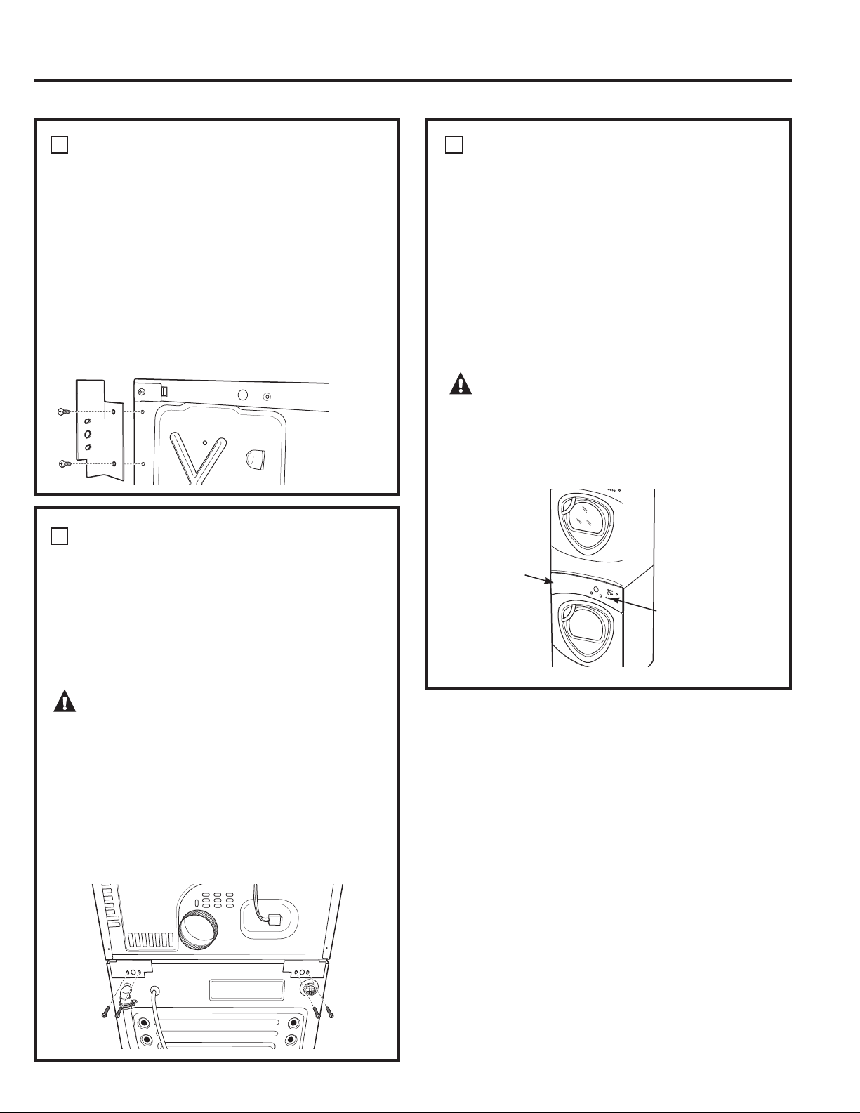
146
CÓMO INSTALAR EL SOPORTE EN LA
SECADORA
3
CÓMO INSTALAR LA SECADORA Y EL
SOPORTE EN LA LAVADORA
4
FINALICE LA INSTALACIÓN
A. Consulte las Instrucciones de instalación de la
lavadora para completar la instalación de la
lavadora.
B. Consulte las Instrucciones de instalación de la
secadora para completar la instalación de la
secadora.
C. Con cuidado deslice o desplace la lavadora
y secadora apiladas a su lugar. Utilice
almohadillas u otro dispositivo para ayudar a
deslizar los artefactos y para proteger el piso.
ADVERTENCIA:
Lesiones personales potenciales. No empuje la
secadora una vez que se haya instalado sobre
la lavadora. Si empuja la secadora puede
pellizcarse los dedos.
5
Coloque
las
manos
aquí
Coloque
las
manos
aquí
Instrucciones de instalación
A.
Levante la secadora sobre la lavadora. Tenga
cuidado de no rayar la parte superior de la lavadora
con los soportes. Proteja el panel de control de la
lavadora con cartón u otra protección. Asegúrese
de levantar la secadora lo suficiente para liberar el
panel de control de la lavadora.
ADVERTENCIA:
Lesiones personales potenciales. Se recomienda que
más de dos personas levanten la secadora hasta su
posición debido a su peso y tamaño. No hacerlo
puede provocar una lesión personal o la muerte.
B. Alinee los orificios del soporte con los orificios
de la parte trasera de la lavadora. Con un
destornillador Phillips, sujete los 2 tornillos auto-
roscantes #8 x 1/2”. Repita en ambos lados de
la lavadora.
A. Alinee los orificios del soporte izquierdo con
los orificios del extremo inferior izquierdo de la
secadora. Utilice un destornillador Phillips para
instalar los 2 tornillos auto-roscantes #12 x 1”.
B. Repita el paso anterior con el soporte derecho
en el extremo inferior derecho de la secadora.
C. Coloque la secadora en posición vertical.
NOTA: Asegúrese de que la secadora se encuentre
sobre un pedazo de material de empaque para
que los soportes sujetos a la parte inferior de la
secadora no dañen el piso.
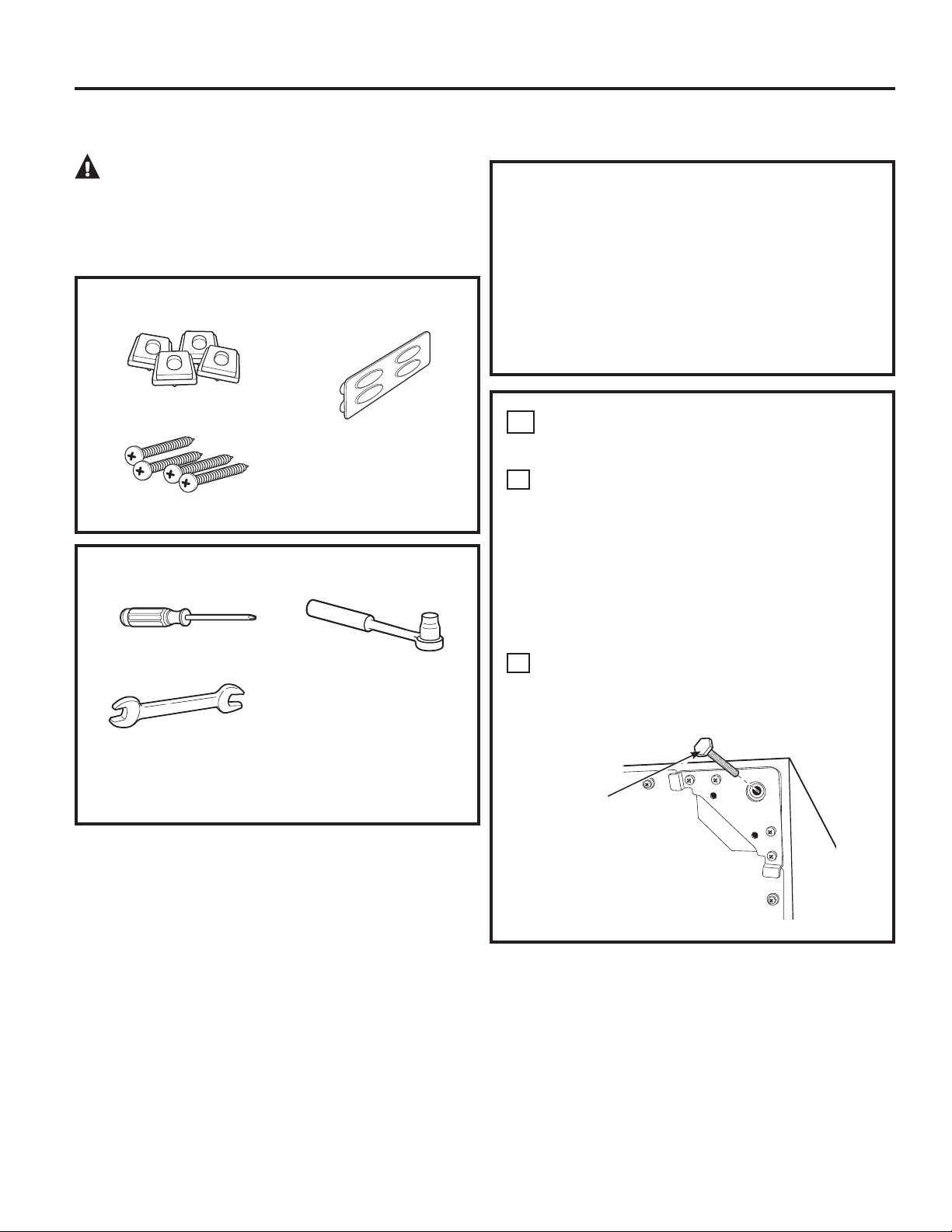
Instrucciones de instalación
1
CÓMO QUITAR LAS PATAS
NIVELADORAS
A
Con cuidado coloque la lavadora o secadora
de costado para tener acceso a las patas
niveladoras ubicadas en la parte inferior del
artefacto.
IMPORTANTE: ¡No apoye la lavadora o la secadora
sobre la parte trasera! No quite los pernos de
embalaje ubicados en la parte trasera de la lavadora.
Los pernos deben conservarse en su lugar hasta
que la lavadora vuelva a la posición vertical.
B
Utilice una llave de extremo abierto para quitar
las patas niveladoras de la lavadora o secadora.
PREPARACIÓN PARA LA INSTALACIÓN
Quite el envoltorio.
La división de cajón se encuentra adherida en la
parte superior de la caja de embalaje. Quite la
división y consérvela para la instalación final.
Aplaste el cartón del producto para poder utilizarlo
para colocar la lavadora o secadora de costado.
Siga usando el cartón para proteger el piso frente al
lugar de instalación.
ADVERTENCIA: Debido al peso y
tamaño de estos productos, y para reducir el riesgo de
lesiones personales o daños al producto, SE NECESITAN
DOS PERSONAS PARA REALIZAR UNA INSTALACIÓN
CORRECTA.
CÓMO INSTALAR EL PEDESTAL (si así lo desea)
CONTENIDOS DEL KIT
4 almohadillas de
apoyo
4 tornillos de montaje
División de cajón
HERRAMIENTAS NECESARIAS
Destornillador Phillips
Llave de extremo
abierto de 9/16” o
llave ajustable
Llave de casquillo de
7 mm”
Quite las 4 patas
niveladoras
147
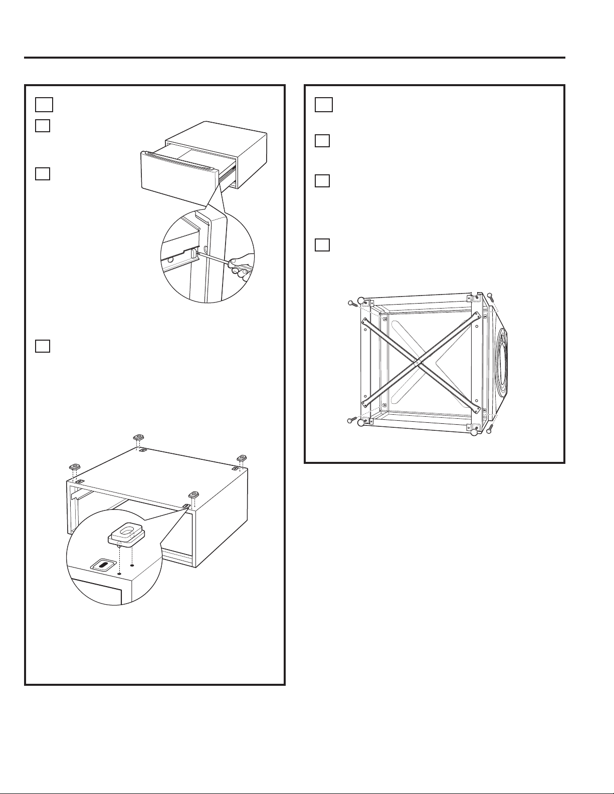
148
3
CÓMO INSTALAR EL PEDESTAL EN
LA LAVADORA O SECADORA
A
Coloque el pedestal contra la parte inferior de
la unidad. Controle que el frente del cajón se
encuentre en el frente de la lavadora.
B
Alinee los orificios del pedestal con los orificios
de la parte inferior de la unidad. Utilice un
destornillador Phillips para instalar los 4 pernos
a través del pedestal y dentro de la unidad; no
ajuste.
C
Deslice el pedestal hacia la unidad, hasta que
se encuentre alineada de frente a parte trasera.
Utilice una llave de casquillo de 7 mm para
ajustar bien los pernos.
2
PREPARE EL PEDESTAL
A
Abra el cajón
hasta el
máximo.
B
Quite los
tornillos de los
deslizadores del
cajón. Quite el
cajón de la base
y deje a un
costado.
SÓLO PARA SECADORAS:
C
Ubique las 4 almohadillas de apoyo en el
paquete de piezas. Cada almohadilla cuenta
con 2 protuberancias que encastran en los
orificios de la parte superior del pedestal.
Presione las almohadillas de goma dentro de
cada grupo de orificios de la parte superior del
pedestal como puede verse.
NOTA: Las almohadillas de apoyo deben
instalarse sólo en la secadora. NO INSTALE ESTAS
ALMOHADILLAS EN EL PEDESTAL DE LA LAVADORA.
Instrucciones de instalación
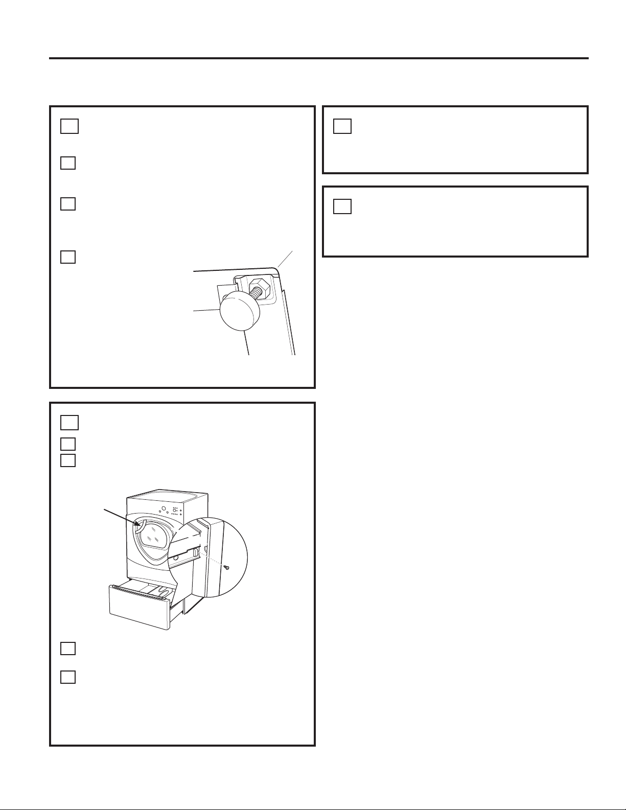
Instrucciones de instalación
CÓMO INSTALAR EL PEDESTAL (si así lo desea) (cont.)
4
CÓMO NIVELAR LA LAVADORA O
SECADORA
A
Coloque la lavadora o secadora en posición
vertical. Colóquela cerca de su ubicación
definitiva.
B
Verifique que la lavadora o secadora estén
niveladas colocando un nivel en la parte
superior. Controle de lado a lado y del frente a
la parte trasera.
C
Utilice una llave de
extremo abierto para
ajustar las patas.
Ajuste la tuerca de
fijación contra la
parte inferior del
pedestal.
NOTA: Para minimizar la
vibración, las tuercas de
fijación deben estar bien ajustadas.
6
QUITE LOS TORNILLOS DE EMPAQUE
Quite los 4 tornillos de embalaje ubicados en la parte
trasera de la lavadora.
5
CÓMO VOLVER A INSTALAR EL CAJÓN
A
Verifique que los deslizadores estén cerrados.
B
Abra el cajón. Alinee los soportes del cajón
con los deslizadores de cada lado.
C
Vuelva a instalar los tornillos originales dentro
de cada deslizador. Ajuste los dos tornillos.
D
Abra el cajón por completo. Deslice la división
del cajón dentro de las ranuras del centro del
cajón. El cajón debe deslizarse suavemente
cuando se lo cierra.
7
FINALICE LA INSTALACIÓN
Consulte las Instrucciones de instalación de la
lavadora o secadora para finalizar la instalación.
División
del
cajón
149
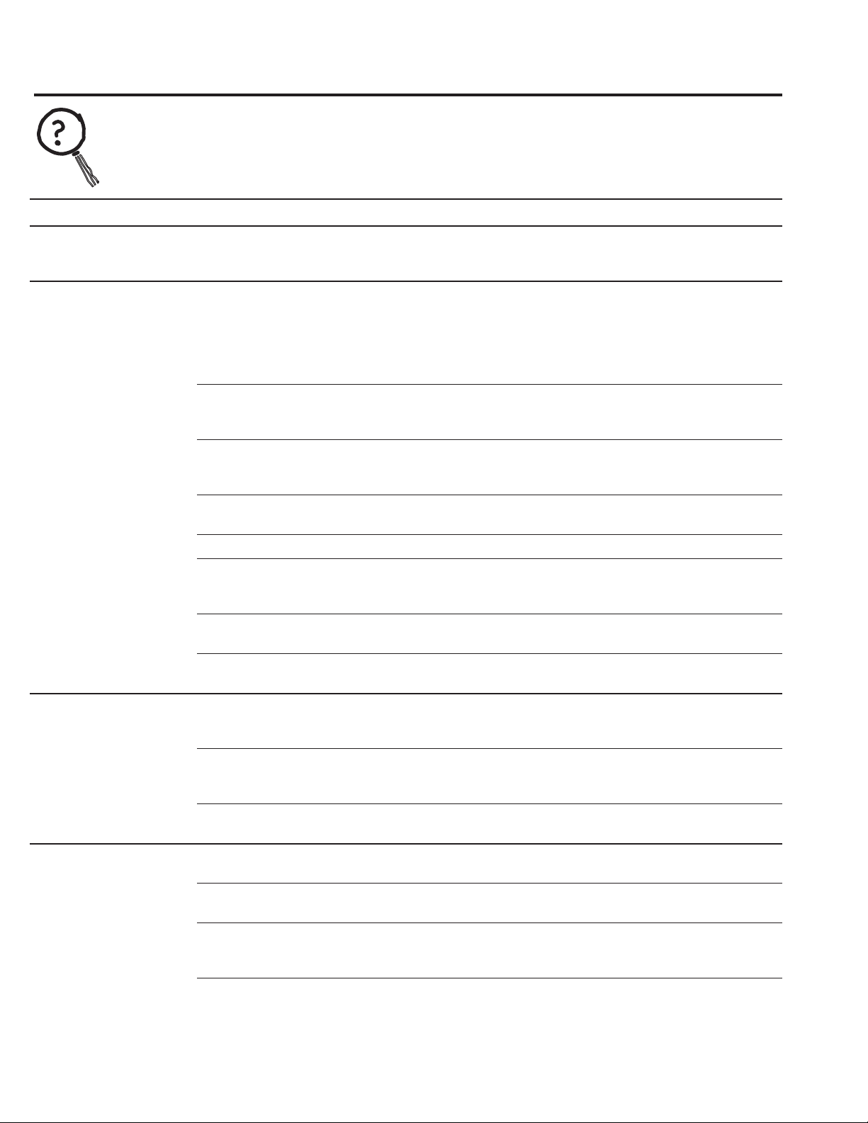
150
Consejos para la solución de problemas
¡Ahorre tiempo y dinero! Consulte primero las tablas de las páginas siguientes y
quizás no necesite llamar al servicio de asistencia técnica..
Problema Causas posibles Solución
La secadora se mueve El movimiento/ruido es normal. • Desplace la secadora a un lugar nivelado, o ajuste
o hace ruido La secadora puede estar colocada las patas niveladoras según sea necesario.
en un lugar desnivelado
Las prendas tardan Conducto inadecuado u obstruido • Controle las Instrucciones de instalación para verificar que
mucho en secarse la ventilación de la secadora sea la correcta.
• Verifique que el conducto se encuentre limpio, libre
de abolladuras y sin obstrucciones.
•
Controle que el regulador de tiro externo de pared funcione bien.
Clasificación inadecuada • Separe prendas pesadas de livianas (generalmente, una
carga bien clasificada para la lavadora es una carga bien
clasificada para la secadora).
Cargas grandes de telas pesadas • Las telas grandes y pesadas contienen más humedad y
(como toallas de playa) tardan más en secarse. Separe las telas grandes y pesadas
en cargas más pequeñas para acelerar el tiempo de secado.
Los controles están mal • Ajuste las configuraciones de control a la carga que esté
configurados secando.
El filtro de pelusas está lleno • Limpie el filtro de pelusas antes de cada carga.
Fusible quemado o disyuntor • Cambie los fusibles o reconfigure los disyuntores. Ya que
accionado la mayoría de las secadoras utilizan 2 fusibles/disyuntores,
asegúrese de que ambos estén funcionando.
Carga excesiva/cargas • No coloque más de una carga en la secadora por vez.
combinadas
Poca carga • Si va secar sólo una o dos prendas, agregue algunas
más para asegurar un secado correcto.
Las teclas de control Los controles se accionaron • Presione START/PAUSE (inicio/pausa).
no responden accidentalmente en el modo
de servicio
Los controles se accionaron • Sostenga el botón LOCK (bloqueo) durante 3 segundos
accidentalmente en el modo para desbloquear la secadora.
de de bloqueo
Los controles efectuaron una • Reconfigure el disyuntor.
operación incorrecta
La secadora no se El panel de control está “dormido” • Esto es normal. Presione POWER (encendido) para activar
enciende el panel de control.
La secadora está desenchufada • Verifique que el enchufe de la secadora esté bien colocado
en el tomacorriente.
Fusible quemado/disyuntor • Verifique la caja de fusibles/disyuntor del edificio y cambie
accionado el fusible o reconfigure el disyuntor. NOTA: Las secadoras
eléctricas utilizan dos fusibles o disyuntores.
La secadora se puso en pausa • Si la luz del botón START/PAUSE destella, la secadora se
accidentalmente cuando se iniciaba
encuentra en pausa. Presione START/PAUSE para volver
Delay Start (inicio retardado) a iniciar la cuenta regresiva.
Antes de llamar al servicio de asistencia técnica…
Problema Causas posibles Solución
Las prendas están Secado excesivo • Seleccione un tiempo de secado más corto.
arrugadas
• Quite las prendas cuando todavía tienen una pequeña
cantidad de humedad. Seleccione una configuración
LESS DRY (menor seco) o DAMP (húmedo).
Se han dejado las prendas • Retire la ropa cuando finalice el ciclo y dóblela o cuélguela
en la secadora después inmediatamente, o utilice la opción EXTEND TUMBLE
de finalizado el ciclo (secado prolongado).
Carga excesiva • Divida las cargas más grandes en cargas más pequeñas.
Las prendas encogen Algunas telas encogen • Para que no encojan, siga las instrucciones de cuidado
naturalmente cuando se las lava. de la prenda al pie de la letra.
Otras pueden lavarse sin
• Algunas prendas pueden plancharse y volver a su forma
problemas, pero encogerán
original después del secado.
en la secadora
• Si tiene miedo de que una prenda determinada encoja,
no la lave a máquina ni la seque con secadora.
Manchas grasosas Uso indebido del suavizante • Siga las instrucciones del paquete de suavizante.
en la ropa
Secar prendas sucias con limpias • Use su secadora sólo para secar ropa limpia. La ropa sucia
puede manchar prendas y la secadora.
La ropa no estaba • A veces las manchas no se ven cuando la ropa está
completamente limpia mojada pero aparecen después del secado. Utilice
procedimiento de lavado adecuados antes del secado.
Pelusas en la ropa El filtro de pelusas está lleno • Limpie el filtro de pelusas antes de cada carga.
Clasificación inadecuada • Separe las telas que producen pelusas (como el chenille)
de las que atraen pelusas (como el corderoy).
La electricidad estática puede • Ver sugerencias en esta sección bajo ESTÁTICA.
atraer pelusas
Carga excesiva • Divida las cargas más grandes en cargas más pequeñas.
Se ha dejado en los bolsillos • Vacíe todos los bolsillos antes de lavar la ropa.
papel, pañuelos de papel, etc.
Se produce estática No se utilizó suavizante • Use suavizante de ropa.
• El acondicionador de telas Bounce
®
en hojas ha sido
aprobado para su uso en todas las secadoras GE cuando
se utiliza de acuerdo con las instrucciones del fabricante.
Secado excesivo • Use suavizante de ropa.
• Ajuste la configuración a LESS DRY o DAMP.
Las telas sintéticas, el • Use suavizante de ropa.
planchado permanente y las
mezclas pueden provocar estática
Los cuellos y las cinturas
El monitor de secado detecta • Seleccione SPEED DRY (secado rápido) o TIMED DRY
todavía están húmedos que la mayoría de las prendas (secado temporizado) para secar cuellos y cinturas.
al finalizar el ciclo se encuentran secas En el futuro, cuando seque una carga con cuellos
y cinturas, seleccione MORE DRY (más seco).
Pequeña variación del Esto es normal • Debido a las propiedades metálicas de la pintura utilizada
color metálico con este producto único, pueden ocurrir pequeñas
variaciones de color debido ángulos de visualización
y condiciones de iluminación.
Antes de llamar al servicio de asistencia técnica… GEAppliances.com
Consejos para la solución de problemas.
151
Antes de llamar al servicio de asistencia técnica…
Problema Causas posibles Solución
Se seleccionó el nivel de La carga incluye una mezcla • Cuando combine telas pesadas y livianas, seleccione
secado DRY (seco) pero de telas pesadas y livianas MORE DRY (más seco).
la carga sigue húmeda
El sistema de salida se encuentra • Inspeccione y limpie el sistema de salida.
bloqueado
No se ven números La secadora monitorea • Esto es normal. Cuando la secadora detecta un nivel
durante el ciclo, sólo luces continuamente la cantidad bajo de humedad en la carga, ésta mostrará el tiempo
de humedad de las ropas restante de secado.
El tiempo restante saltó
El tiempo estimado puede cambiar
• Esto es normal.
a un número más bajo
cuando se está secando una carga
más pequeña de lo normal
No se puede hacer una El nivel de secado, la temperatura • Esto es normal.
selección y la secadora o la opción que trata de
emite dos pitidos seleccionar es incompatible con
el ciclo de secado seleccionado
La secadora funciona Se seleccionó la opción • Esto es normal. Durante el secado prolongado, no puede
pero se ve 00 en el EXTEND TUMBLE verse el tiempo restante. La opción de secado prolongado
tiempo restante (secado prolongado) dura aproximadamente 20 minutos.
Clean Lint Filter Se activó el botón POWER • Presione START/PAUSE (inicio/pausa) para comenzar
(mensaje) (encendido) un ciclo de secado y el mensaje desaparecerá.
La secadora no calienta Fusible quemado/disyuntor • Verifique la caja de fusibles/disyuntor del edificio y
accionado; la secadora gira cambie ambos fusibles o reconfigure ambos disyuntores.
pero no calienta La secadora puede girar si sólo se ha quemado un fusible
o se ha accionado un disyuntor.
El suministro de gas no funciona • Verifique que la boca de gas de la secadora y la boca
principal se encuentren abiertas.
El tanque de suministro de gas • Rellene o cambie el tanque. La secadora debe calentarse
PL está vacío o ha habido una cuando se reestablezca el servicio.
interrupción del servicio de gas
natural (en modelos a gas)
Tiempos de secado Tipo de calor • El tiempo de secado cambia se acuerdo con el tipo de calor
desiguales utilizado. Si recientemente ha cambiado de una secadora
eléctrica a una a gas (natural o PL), o viceversa, los tiempos
de secado pueden cambiar.
Tipo de carga y condiciones • El tamaño de carga, tipos de telas, humedad de las
de secado prendas y la longitud y condición del sistema de salida
afecta los tiempos de secado.
Brillo en la parte Calentadores detrás del tambor • Esto es normal. En ciertas condiciones de secado
trasera del tambor e iluminación ambiente, el brillo de los calentadores puede
verse en la parte trasera del tambor.
Las prendas siguen La puerta se abrió en la mitad • Debe seleccionarse un ciclo de secado cada vez que
húmedas y la secadora del ciclo. Luego se quitó la carga se ingresa una carga.
se apagó después de un de la secadora y se colocó una
período corto nueva carga sin seleccionar un
nuevo ciclo
Carga pequeña • Cuando se sequen 3 prendas o menos, seleccione SPEED
DRY (secado rápido) o TIMED DRY (secado temporizado).
La carga ya estaba seca • Seleccione SPEED DRY o TIMED DRY para secar cuellos y
con excepción de los cuellos cinturas. En el futuro, cuando seque una carga con
y las cinturas cuellos y cinturas, seleccione MORE DRY.
La secadora está desnivelada • Desplace la secadora a un lugar nivelado o ajuste las patas
niveladoras según sea necesario.
152

Problema Causas posibles Solución
Durante un ciclo de vapor El vapor se condensa en • Esto es normal.
no pueden verse las la puerta interna
prendas porque la puerta
está muy cubierta por vapor
Se ve agua dentro de la El vapor se condensa sobre • Esto es normal.
puerta y sobre el filtro estas superficies
de pelusa cuando se
abre la puerta después
del ciclo de vapor
Pequeñas áreas de El vapor se condensa • Seleccione un ciclo más corto.
las prendas se encuentran en el tambor interno
húmedas después del
El ciclo o tiempo del ciclo • Reduzca manualmente el tiempo del ciclo.
ciclo de vapor
seleccionado es muy largo
para el tamaño de la carga
Hay una pequeña cantidad Tamaño de carga inadecuado • Seleccione un ciclo más corto. Reduzca manualmente
de agua sobre el piso para el ciclo de vapor el tiempo del ciclo.
frente a la secadora seleccionado, el vapor excedente
se condensa dentro del gabinete
y se escapa
Hay agua en el piso en La conexión de manguera de agua • Ajuste la conexión.
la parte trasera de a la válvula se encuentra floja
la secadora
La manguera no cuenta • Instale la arandela de goma provista con la manguera.
con la arandela de goma en
la conexión con la válvula
La secadora hace ruido La válvula de agua está • Esto es normal.
a agua abierta llenando el generador
de vapor
El generador de vapor está • Esto es normal.
suministrando vapor al tambor
Cae agua de la puerta El vapor se condensa en • Esto es normal.
cuando se la abre la puerta interna
después de un ciclo
de vapor
No puede verse vapor El vapor se libera en un • Esto es normal.
al comienzo del ciclo momento diferente en el ciclo
No se ve vapor en La boquilla de vapor puede • Llame al 800.GE.CARES para solicitar el kit de reemplazo
ningún momento estar bloqueada con suciedad de boquilla WE25M71 o para solicitar un técnico que lo
durante el ciclo proveniente del suministro de agua reemplace por usted.
Las prendas siguen Demasiadas prendas • Cargue menos prendas; incremente el tiempo
arrugadas después manualmente.
del ciclo de vapor
La secadora continúa Se seleccionó la rotación • Asegúrese de que la opción de rotación extendida
la rotación después extendida no esté seleccionada.
de que la pantalla
dice Complete (finalizado)
Antes de llamar al servicio de asistencia técnica… GEAppliances.com
153

Nota…
154
155
Garante: General Electric Company. Louisville, KY 40225
Período: Se sustituirá:
Garantía de la secadora GE. (Para clientes de Estados Unidos)
Todos los servicios de garantía se ofrecen a través de nuestros centros
de asistencia técnica o un técnico autorizado de Customer Care
®
.
Para programar servicio de asistencia técnica, en línea, visite la página
GEAppliances.com o llame al 800.GE.CARES (1.800.432.2737). Cuando
llame para solicitar servicio, por favor tenga a mano el número de serie y
el número de modelo.
Esta garantía se extiende al comprador original y cualquier comprador posterior de productos comprados para uso
residencial dentro des Estados Unidos. Si el producto está situado en un área que no dispone de servicio por parte de un
proveedor de servicio autorizado de GE, podría tener que hacerse cargo de los costes de envío o bien podría solicitársele
que lleve el producto a una centro de servicio de GE autorizado para realizar la reparación. En Alaska, la garantía excluye
el costo de envío o las visitas de servicio a su casa.
Algunos estados no permiten la exclusión o las limitaciones de daños incidentales o consecuenciales. Esta garantía da
derechos legales específicos, y usted podría tener otros derechos que variarán de estado a estado. Para saber cuáles son
sus derechos legales, consulte a la oficina de asuntos del consumidor local o la oficina del Prucurador (Attorney General)
en su localidad.
Engrape el recibo aquí.
Se necesita el comprobante
con la fecha de compra original
para que la garantía cubra los
servicios.
Un año Cualquier pieza de la secadora que falle debido a un defecto de los materiales o mano
Desde la fecha de de obra. Durante esta garantía limitada de un año, GE también ofrece, en forma gratuita,
compra original toda la mano de obra y los costos de servicio para reemplazar la pieza defectuosa.
Segundo año Cualquier pieza de la secadora que falle debido a un defecto de los materiales o mano de obra.
Desde la fecha de Durante esta garantía limitada adicional de un año, usted será responsable de cualquier clase
compra original de costos de mano de obra o de servicios relacionados.
Del segundo al El tambor de secado extra grande o de súper capacidad y la placa electrónica principal de
quinto año control si alguna de estas piezas fallara debido a un defecto de materiales o mano de obra. Durante
Desde la fecha de esta garantía limitada adicional de cuatro años, usted será responsable de cualquier clase de costos
compra original de mano de obra o de servicios relacionados.
(;&/86,Ï1'(*$5$17Ë$6,03/Ë&,7$6³6X~QLFR\H[FOXVLYRGHUHFKRHVODUHSDUDFLyQGHOSURGXFWRWDO\
como se indica en esta Garantía limitada. Cualquier garantía implícita, incluyendo las garantías implícitas
de comerciabilidad o adecuación para un fin determinado, están limitadas a un año o el período de tiempo
más breve permitido por la ley.
Visitas a su hogar para enseñarle a usar el producto.
Instalación, entrega o mantenimiento inadecuados.
Fallas del producto debido a abuso, uso indebido, uso
diferente para el que fue diseñado, o uso comercial.
Recambio de la bombilla de luz después de su vida
útil esperada.
Reemplazo de fusibles domésticos o la reconfiguración
de los interruptores de circuito.
Daños al producto provocados por accidentes, incendios,
inundaciones o fuerza mayor.
Daños incidentales o resultantes provocados por posibles
defectos en este artefacto.
Daños provocados después de la entrega.
Producto no accesible para prestar el servicio técnico
solicitado.
Defectos o daños causados por la operación en
temperaturas bajo cero C.
Productos que no están defectuosos o dañados o que
funcionan según la descripción del Manual del usuario.
No se encuentra cubierto:
Apoyo al cliente.
Sitio Web de GE Appliances
En los EE.UU.: GEAppliances.com
¿Tiene una consulta o necesita ayuda con su aparato? ¡Visite el Sitio Web de GE Appliances las 24 horas al día, todos
los días del año! Para una mayor comodidad y un servicio más rápido, ahora usted puede bajar los Manuales del
Propietario, solicitar piezas o programar atención on-line.
En Canadá: www.GEAppliances.ca.
Programe una reparación En los EE.UU.: GEAppliances.com
El servicio experto de reparación de GE está sólo a un paso de su hogar. ¡Programe on-line el servicio técnico a su
conveniencia cualquier día del año! O llame al 800.GE.CARES (800.432.2737) durante horario normal de trabajo.
En Canadá, llame al 1.800.561.3344
Estudio de diseño para la vida real En los EE.UU.: GEAppliances.com
GE apoya el concepto de Diseño Universal: Productos, servicios y ambientes que pueden ser utilizados por personas
de todas las edades, tamaños y capacidades. Reconocemos la necesidad de la creación de diseños para una amplia
gama de capacidades y limitaciones físicas y mentales. Para más detalles sobre las aplicaciones de Diseño Universal
de GE, incluyendo ideas de diseño de cocina para personas con discapacidades, visite el Sitio Web hoy mismo. Para
las personas con problemas auditivos, llame al 800.TDD.GEAC (800.833.4322).
En Canadá, comuníquese con: Manager, Consumer Relations, Mabe Canada Inc.
Suite 310, 1 Factory Lane
Moncton, N.B. E1C 9M3
Garantías extendidas En los EE.UU.: GEAppliances.com
Adquiera una garantía extendida de GE y averigüe sobre descuentos especiales disponibles durante la vigencia de
su garantía. Usted puede adquirirla on-line en cualquier momento, o llamar al 800.626.2224 en horario normal de
trabajo. El Servicio Doméstico al Consumidor de GE también lo ayudará después de que su garantía haya expirado.
En Canadá, llame al 1.888.261.2133
Piezas y accesorios En los EE.UU.: GEApplianceparts.com
Las personas calificadas para arreglar sus propios aparatos pueden recibir las piezas o accesorios directamente en
sus hogares (se aceptan las tarjetas VISA, MasterCard y Discover). Solicítelos on-line hoy mismo, las 24 horas del día
o por teléfono al 800.626.2002 en horario normal de trabajo.
Las instrucciones incluidas en este manual cubren los procedimientos a realizar por cualquier usuario. Personal de
servicio técnico calificado debe efectuar otra clase de arreglos. Debe tenerse mucho cuidado, porque los arreglos
inadecuados pueden provocar un funcionamiento poco seguro.
Los clientes de Canadá deben consultar las páginas amarillas para encontrar el centro de servicio Mabe más cercano,
o deben llamar al 1.800.661.1616.
Comuníquese con nosotros En los EE.UU.: GEAppliances.com
Si no se encuentra satisfecho con el servicio que recibe de GE, comuníquese con nosotros a través del Sitio Web con
todos los detalles, incluyendo número de teléfono, o escríbanos a: General Manager, Customer Relations
GE Appliances, Appliance Park
Louisville, KY 40225
En Canadá: www.GEAppliances.ca, o escriba a: Director, Consumer Relations, Mabe
Canada Inc.
Suite 310, 1 Factory Lane
Moncton, N.B. E1C 9M3
Registre su aparato En los EE.UU.: GEAppliances.com
Registre su nuevo aparato on-line, ¡como le resulte más conveniente! Una inscripción de producto oportuna
mejorará y acelerará las comunicaciones y el servicio según los términos de la presente garantía, si surgiera la
necesidad. Usted también puede enviar por correo la tarjeta de inscripción pre-impresa incluida con el material de
empaque. En Canadá: www.GEAppliances.ca
156

