Loading ...
Loading ...
Loading ...
Air Purging
Any air or moisture remaining in the refrigerant
system has undesirable effects as indicated below.
■Pressure in the system rises.
■Operating current rises.
■Cooling (or heating) efficiency drops.
■Moisture in the refrigerant circuit may freeze and
block capillary tubing.
■Water may lead to corrosion of parts in the
refrigerant system.
The indoor unit and tubing between the indoor
and outdoor units must be leak-tested and the
system evacuated to remove any noncondensables
and moisture.
NOTE: The outdoor unit contains R22 charge for the
total system.
Air purging with a vacuum pump.
Preparation:
Check that each tube (both liquid and gas side
tubes) between the indoor and outdoor units has
been properly connected and all wiring for the test
run has been completed. Remove the valve caps
from both the gas and the liquid side service valves
on the outdoor unit. Note that both liquid and gas
side service valves on the outdoor unit are kept
closed at this stage.
NOTE: The outdoor unit contains R22 charge for the
total system.
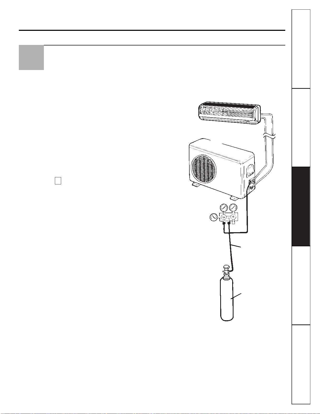
Leak Test:
1
Connect a manifold valve (with pressure gauges)
and dry nitrogen gas cylinder to the suction
service port.
2
Pressurize the system to no more than 150
P.S.I.G. with dry nitrogen gas and close the
cylinder valve when the gauge reading reaches
150 P.S.I.G. Next, test for leaks with liquid soap.
CAUTION: To avoid nitrogen entering the refrigerant system
in a liquid state, the top of the cylinder must be higher than its
bottom when you pressurize the system. Usually, the cylinder
is used in a vertical standing position.
3
Do a leak test of all joints of the tubing (both
indoor and outdoor) and both gas and liquid side
service valves. Bubbles indicate a leak. Be sure to
wipe off the soap with a clean cloth.
4
After the system is found to be free of leaks,
relieve the nitrogen pressure by loosening the
charge hose connector at the nitrogen cylinder.
When the system pressure is reduced to normal,
disconnect the hose from the cylinder.
Indoor unit
Outdoor unit
Manifold valve
Pressure gauge
Charge hose
Nitrogen gas cylinder
(in vertical standing
position).
A
7
Customer ServiceTroubleshooting Tips
Operating Instructions
Safety Instructions
Installation Instructions
25
Loading ...
Loading ...
Loading ...