Loading ...
Loading ...
Loading ...
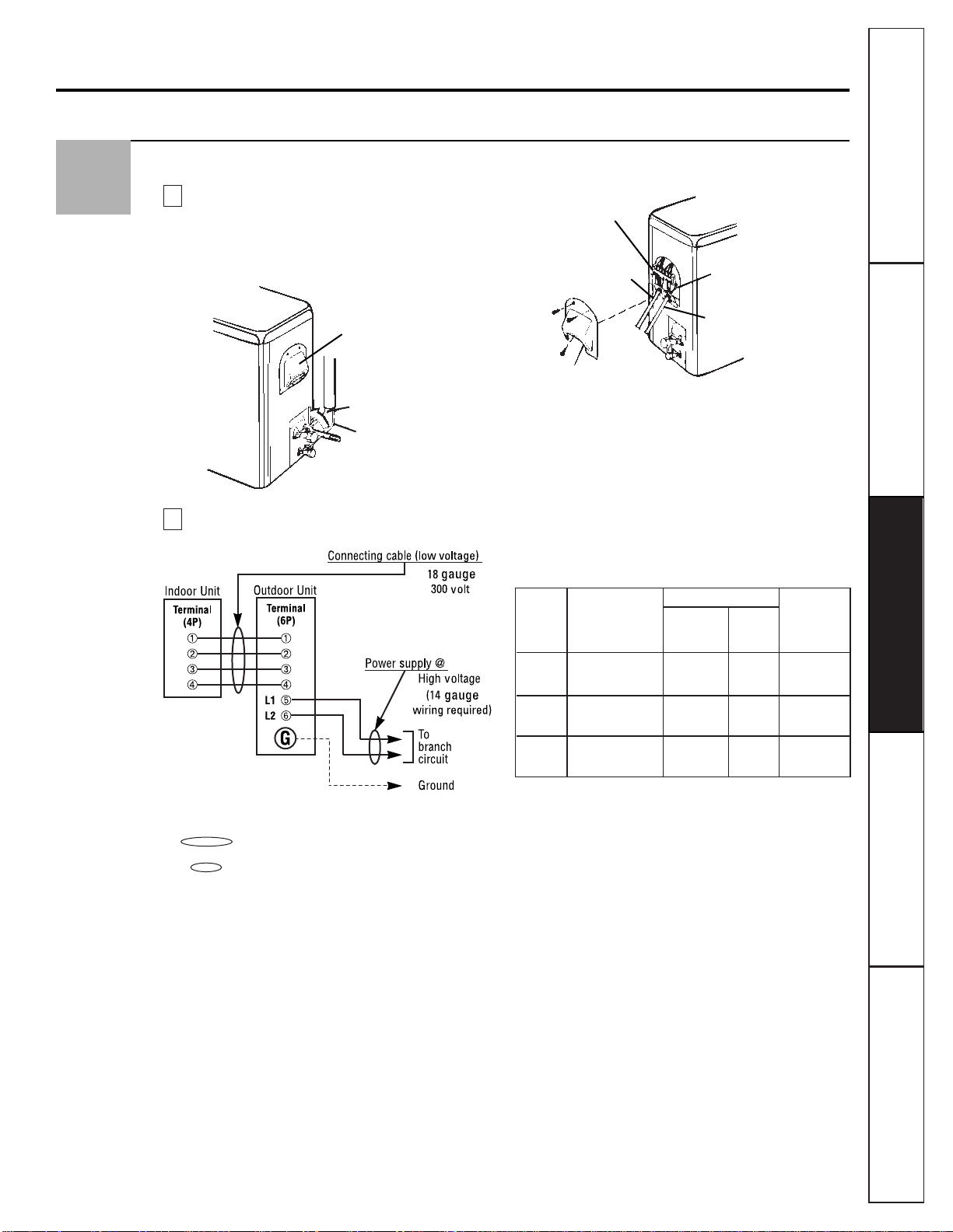
Connection of the Pipes and the Cable to the Outdoor Unit
Connecting the pipings to the outdoor unit.
1
Align the center of the pipings and
sufficiently tighten the flare nut by hand.
2
Tighten the flare nut with a wrench.
Wiring diagram:
NOTES:
■ shows field wiring (low voltage).
■ shows power source wiring.
■Separately wire the high and low voltage lines.
■Use heat-proof electrical wiring capable of
withstanding temperatures of up to 167° F.
■Use outdoor and waterproof connection cable
rated more than 300V for the connection
between indoor and outdoor units. (For
example, Type SJO-WA.)
WARNING
■Be sure to comply with local codes to route the
wire from the indoor unit to the outdoor unit
(size of wire and wiring method, etc.).
■Every wire must be connected securely.
■No wire should be allowed to touch refrigerant
tubing, the compressor or any moving parts.
Outdoor unit
Terminal block
Low voltage wiring
Cover control
Conduit panel
Supply voltage
connection
B
Gas side piping
(larger dia.)
Liquid side piping
(smaller dia.)
Outdoor unit
Wiring access cover
A
5
AWG(Min.)
Fuse or
Power Supply Low
Breaker
Model
Source voltage voltage
Capacity
connection wiring
9K 115V 14 18 15 amps
60Hz – 1Ph
12K 115V 14 18 20 amps
60Hz – 1Ph
18K 230/208V 14 18 15 amps
60Hz – 1Ph
Customer ServiceTroubleshooting Tips
Operating Instructions
Safety Instructions
Installation Instructions
21
Loading ...
Loading ...
Loading ...