Loading ...
Loading ...
Loading ...
24
Customer Service Troubleshooting Tips
Operating Instructions
Safety Instructions
Installation Instructions
Customer Service Troubleshooting Tips
Installation Instructions
Safety Instructions
Operating Instructions
Customer Service Troubleshooting Tips
Installation Instructions
Safety Instructions
Operating Instructions
Installation instructions.
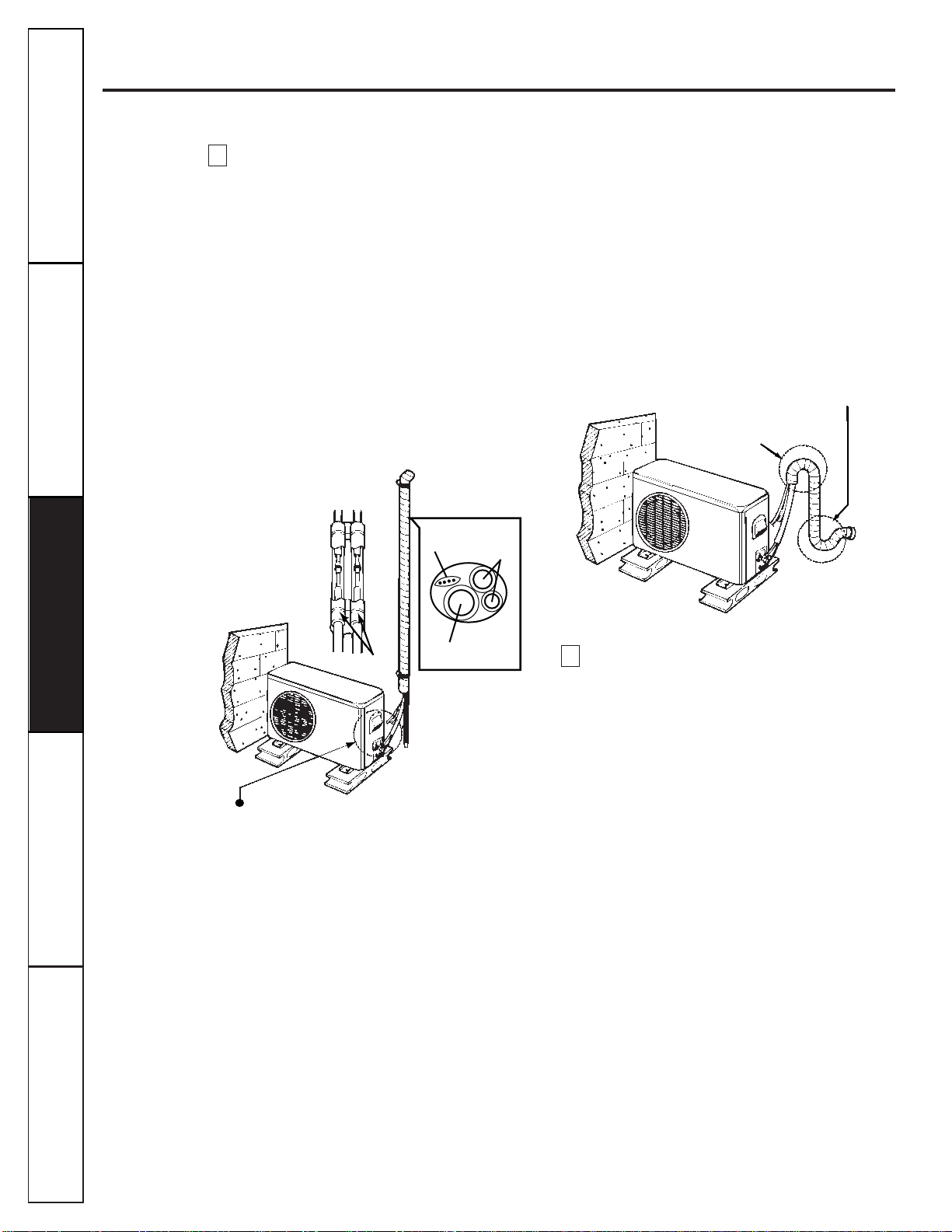
Form the pipings by wrapping the connecting
portion of the indoor unit with insulation
material and secure it with two plastic bands
(for the right pipings).
If you want to connect an additional drain
hose, the end of the drain outlet should be
routed above the ground. Secure the drain line
appropriately.
■If the outdoor unit is being installed below the
position of the indoor unit:
1
Tape the pipings, drain hose and connecting
cable from down to up.
2
Form the pipings gathered by taping along the
exterior wall and fix them onto the wall by
saddle or equivalent.
■If the outdoor unit is being installed above the
position of the indoor unit:
1
Tape the pipings and connecting cable from
down to up.
2
Form the pipings gathered by taping along the
exterior wall. The trap should be formed up to
prevent water from entering into the room.
3
Fix the pipings onto the wall by saddle or
equivalent.
A plastic drain elbow is provided with the
outdoor heat pump unit for routing any
condensation away from the outdoor unit
basepan. Attach the elbow to the basepan
near the compressor and then attach a hose
(that you provide) to the other end to route
the water away.
F
Seal small openings
around pipings with
a gum type sealer.
Trap
Seal small openings
around pipings with
a gum type sealer.
Plastic
band
Trap is required to prevent water from
entering into electrical parts.
Drain hose
Pipings
Connecting
cable
E
Loading ...
Loading ...
Loading ...