Loading ...
Loading ...
Loading ...
18
Customer Service Troubleshooting Tips
Operating Instructions
Safety Instructions
Installation Instructions
Customer Service Troubleshooting Tips
Installation Instructions
Safety Instructions
Operating Instructions
Customer Service Troubleshooting Tips
Installation Instructions
Safety Instructions
Operating Instructions
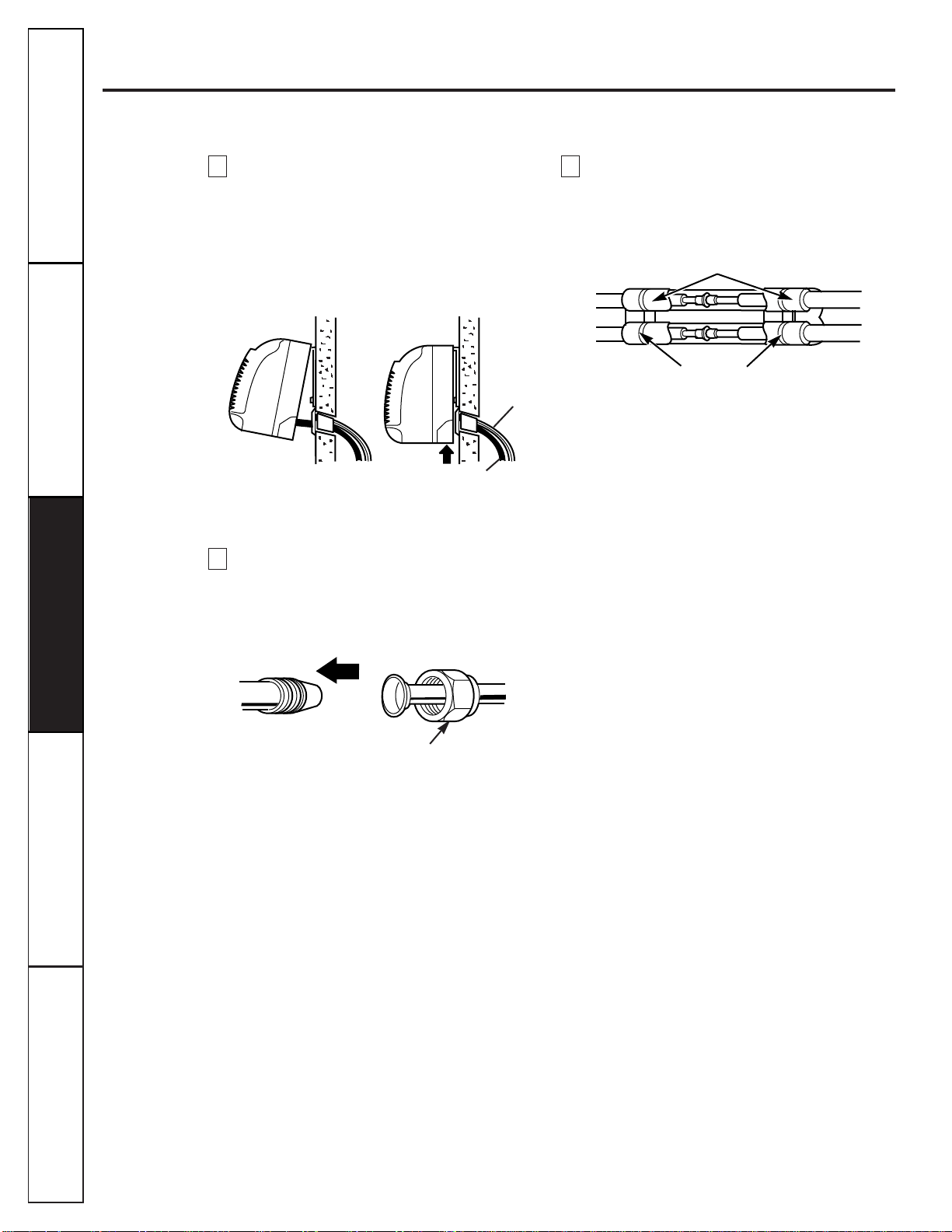
Installation instructions.
Indoor unit installation.
Hook the indoor unit onto the upper
portion of the installation plate. (Engage
the two hooks of the rear top of the indoor
unit with the upper edge of the installation
plate.) Ensure that the hooks are properly
seated on the installation plate by moving it
left and right.
Connecting the pipings to the indoor unit.
1
Align the center of the pipings and
sufficiently tighten the flare nut by hand.
2
Tighten the flare nut with a wrench.
Wrap the insulation material around the
connecting portion.
CAUTION:Be careful to arrange the pipings, drain hose
and cables as shown on page 17 by connecting them to the
indoor unit.
H
G
F
Press the lower left and right sides of the unit against
the installation plate until the hooks engage with their
slots (clicking sound).
Drain hose
Connecting
cable
Plastic bands
Isulation material
Wrap insulation material around the connecting portion.
Indoor unit tubing
Flare nut
Piping
Loading ...
Loading ...
Loading ...