Loading ...
Loading ...
Loading ...
IMPORTANTSAFETY
INSTRUCTIONS
Anti-Tip Bracket (contd.)
Step 2
Anti-tip bracket installation
A. Wood Construction:
t. Floor: Drill a W pilot hole in
the center of each pre-marked
wood floor hole position(a nail
or awl may be used if a drill is
not available),
AND
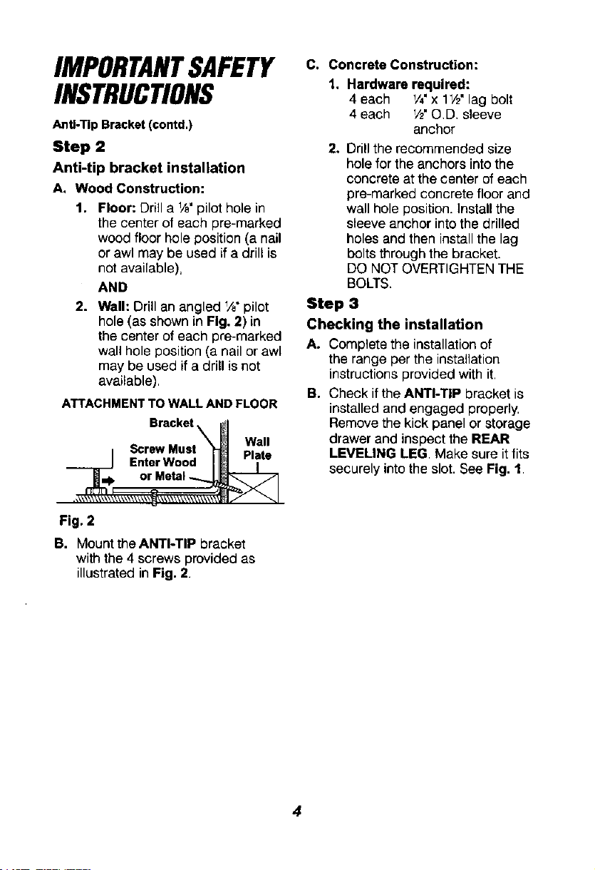
2. Wall: Drill an angled _,_"pilot
hole (as shown in Fig. 2) in
the center of each pre-marked
wall hole position (a nail or awl
may be used if a drill is not
available).
ATTACHMENT TO WALL AND FLOOR
Bracket
• ScrewMust W.all
EnterWood t-tat_"_1 or Metal;\_
\\ \\\\\ \ \_ \t_\\\\ \\\
Fig. 2
B. Mount theANTI-TIP bracket
with the 4 screws provided as
illustrated in Fig, 2.
C, Concrete Construction:
1. Hardware required:
4 each V4"x l_/z"lag bolt
4 each V2"O.D. sleeve
anchor
2. Drill the recommended size
hole for the anchors into the
concrete at the center of each
pre-marked concrete floor and
wall hole position, install the
sleeve anchor into the drilled
holes and then install the lag
bolts through the bracket.
DO NOT OVERTIGHTEN THE
BOLTS.
Step 3
Checking the installation
A. Complete the installation of
the range per the installation
instructions provided with it.
B. Check if the ANTI-TIP bracket is
installed and engaged properly
Remove the kick panel or storage
drawer and inspect the REAR
LEVELING LEG. Make sure it fits
securely into the slot. See Fig. 1.
Loading ...
Loading ...
Loading ...