Loading ...
Loading ...
3
min.100
mm
"0"
mm
"0"
mm
min
"60"
mm
min
"60"
mm
"0"
mm
"0"
mm
Fig. A
Clearances to combustible materials
"Any adjoining wall surface (side or rear) situated within 200mm
of any hob burner must be a suitable non-combustible material
from the edge for a height of 150mm for the entire length
of the cooker.
Any combustible construction above the cooker must be at least
650mm above the maintop." Ensure that a power and gas supply
are nearby. The Cooker should be located carefully so that the
heat produced by it has plenty of space to escape. The diagram
below shows an ideal configuration.
Note:
F
itting the adjustable feet ( Fig.1 ).
Fig.1
WARNING: This appliance is not suitable to be installed on
a base
No part of any adjoining wall surface can be made of combustible
materials. The protection of combustible materials
required by Clause 5.12.1.1 of AS5601-2004 is the fixing of 5 mm
thick ceramic tiles to the surface or attaching fire resistant
material to the surface and covering with sheet metal with a minimum
thickness of 0.4 mm.
"If the cooker is being fitted next to cupboards or adjoing wall
surfaces, which are within 200mm from the edge of the hob
burner and of a suitable non-combustible material as specified
in AS5601, then ensure that a distance of at least 6cm is left
between the edge of the cooker and the non-combustible
material. This gap is to allow plenty of space for the heat
produced by the cooker to escape on each side of the cooker.
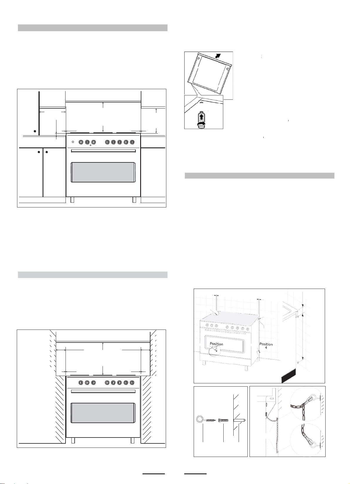
TO FIX THE COOKER TO THE REAR WALL
WARNING - For safety reasons and to prevent tipping of the appliance,
these stabilizing means must be installed.
The cooker is equipped with 2 chains fixed on each side at the rear of
the cooker near the top (see Fig. A). The chains are fitted with "spring
clips" which must be clipped to the "screw eyes".
Install the "screw eyes" as follows :
1.
Drill four 6mm holes (position 1 - 2 - 3 - 4) in the wall
as in Fig. A.
2.
Insert part "R" into the holes then screw in the "screw eyes" part
"G"
see Fig. B.
Note: If the part provided is not suitable for the wall material please
use an appropriate device to ensure secure holding of the "screw
eyes" to the wall.
3.
Bring the cooker near the wall and clip the chains on the
"screw eyes" as in Fig. C.
IMPORTANT: If the cooker is mo ved for any reason
(e.g. maintenance) resulting in the cooker being unclipped from the
wall, the cooker must be re-clipped to the wall at the completion of
the task.
Fig.
B
wal
l
G
R
Hole
Fig.
C
wall
G
Clearances
to
non
-
combustible
materials
min.10
mm
min.
650
mm
min.
400
mm
non-
combustible
materials
min.
650
mm
non-
combustible
materials
chain
550
mm
76
mm
B
P
eforehand:
•
Remove
a
especiall
y
•
Remove
t
P
roceed as f
o
•
Tilt the ap
the floor.
a
ll parts that
y
the pan su
p
t
he accesso
r
o
llows:
pliance by r
a
are not per
m
p
ports and b
u
r
ies from the
a
ising one si
d
m
anently fixe
d
u
rners.
oven.
d
e slightly fr
o
d
,
o
m
Y
o
e
I
f
a
w
c
•
With the
p
feet into t
h
the appli
a
•
Repeat t
h
Y
ou can ma
k
o
rder to level
e
lectricity su
p
f
it is necess
a
djustable fe
e
w
hen the oth
c
ompleted.
p
lates in posi
h
e mounting
a
nce.
h
e process o
n
k
e the final a
d
the applian
c
p
ply have be
e
ary to pull th
e
t in fully. M
a
e
r installatio
n
i
tion, screw t
holes on th
e
n
the other s
d
justments t
o
c
e once the
g
en connecte
e appliance,
a
ke the final
n
tasks hav
e
he adjustabl
e
underneath
ide.
o
the feet in
g
as and
d.
screw the
settings onl
y
e
been
e
of
y
Loading ...
Loading ...
Loading ...