Loading ...
Loading ...
Loading ...
14 49-50300-2
Installation Instructions
INSTALLATION INSTRUCTIONS
CONDENSATION DRAIN
CONNECTION
This unit has a condensate drain; therefore a floor or other
GUDLQQRKLJKHUWKDQ´FPDERYHWKHIORRUPXVW
EHDYDLODEOHLQFORVHSUR[LPLW\WRWKHZDWHUKHDWHUWRDOORZ
for the shortest possible drain line with minimal turns to
be installed. Drain must meet state and local codes. It is
important to install a
3
/4´)137ILWWLQJVXLWDEOHIRUHLWKHUULJLG
RUIOH[LEOHGUDLQOLQHWRWKHSULPDU\GUDLQSRUWFRPLQJRIIWKH
side of the unit. Diameter reductions from a
3
/4´GUDLQOLQH
are discouraged.
(QVXUHWKDWWKHULJLGRUIOH[LEOHGUDLQOLQHPDLQWDLQVD
downward slope to allow for proper gravity drainage of
condensate to the drain and to allow for proper function of
the condensate drain blockage sensor (see page 10). If
no drain is available, then a common condensate pump
with a capacity no less than 1 gallon (3.8L)/day must be
SXUFKDVHGDQGLQVWDOOHG,WLVLPSRUWDQWWRURXWHWKHIOH[LEOH
or rigid drain line so that the discharge water cannot
contact live electrical parts or cause water damage .
Additional parts needed:
)OH[LEOHRUULJLGô´GUDLQOLQHDQGDVVRFLDWHGô)137
fitting
Fitting
Condensate
Drain
2YHUÀRZ
Drain
Line
Fitting
Condensate
Drain
2YHUÀRZ
Drain
Line
(Typical Installations)
THERMAL EXPANSION
If a check valve is present on the inlet water line,
LWZLOOFUHDWHD³FORVHGV\VWHP´+HDWLQJZDWHULQD
closed system creates an increase in pressure within
the water system because the pressure is not able
to dissipate in the main supply line. Referred to as
³WKHUPDOH[SDQVLRQ´WKHUDSLGSUHVVXUHLQFUHDVH
can cause the relief valve to operate (releasing
water) during each heating cycle, potentially causing
premature failure to the valve or even the water
heater. The suggested method of controlling thermal
H[SDQVLRQLVWRLQVWDOODQH[SDQVLRQWDQNLQWKHFROG
water line between the water heater and the check
valve as shown in the following illustrations. Contact
your installing contractor, water supplier, or plumbing
inspector for additional information.
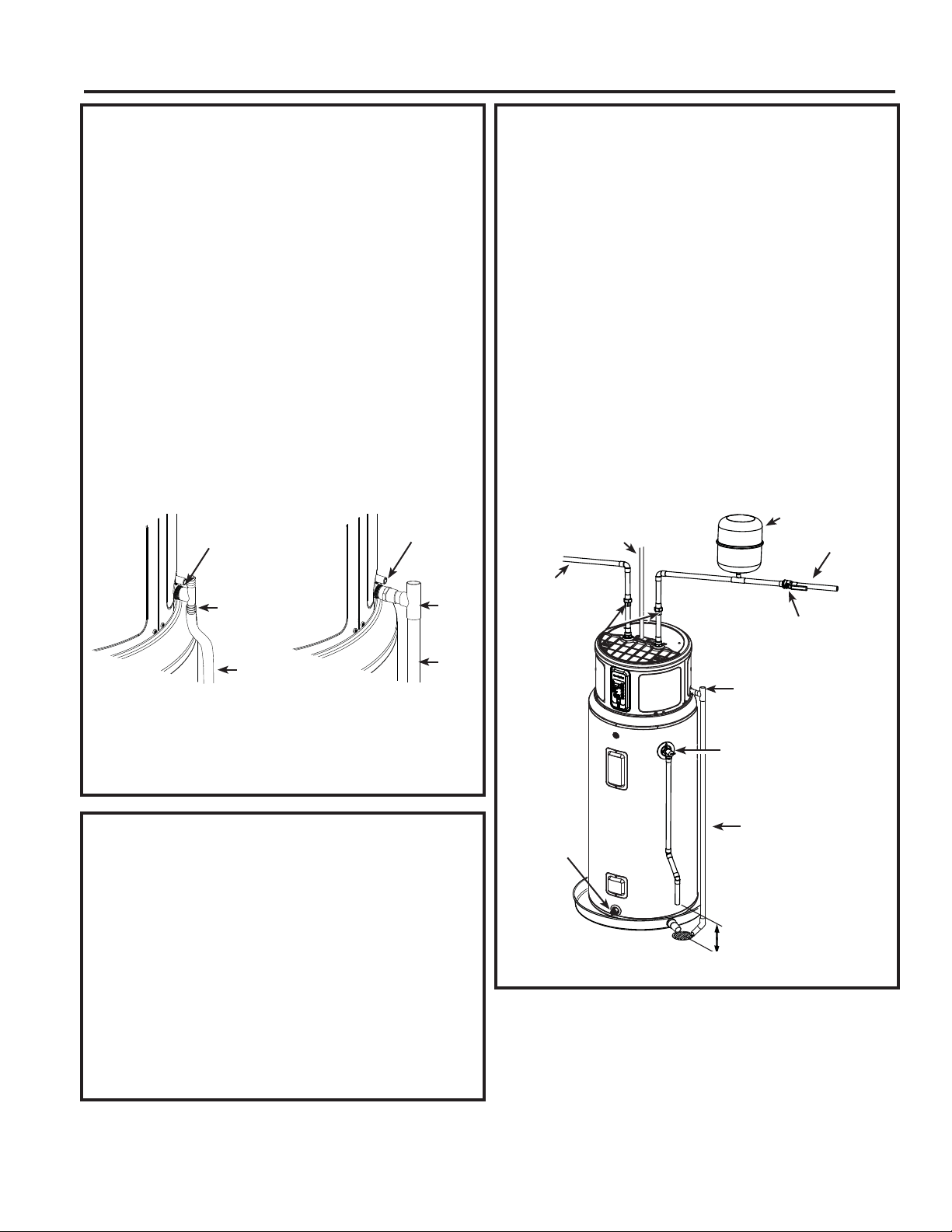
WATER SUPPLY CONNECTIONS
Refer to the illustration below for suggested typical
installation. The HOT and COLD water connections are
FOHDUO\PDUNHGDQGDUHô´137RQDOOPRGHOV:KHQ
FRQQHFWLQJWRWKHLQOHWRXWOHWSRUWVWKHXVHRIô´IHPDOH
NPT tapered thread fittings with use of thread sealant is
recommended. The installation of unions is recommended
on the hot and cold water connections so that the
water heater may be easily disconnected for servicing if
necessary.
NOTE: Install a shut-off valve in the cold water line
near the water heater. This will enable easier service or
maintenance of the unit later.
IMPORTANT: Do not apply heat to the HOT or COLD
water connections. If sweat connections are used,
sweat tubing to adapter before fitting the adapter
to the cold water connections on heater. Any heat
applied to the hot or cold water connection will
permanently damage the internal plastic lining in
these ports.
TYPICAL INSTALLATION
To cold
water supply
Hot water
outlet to
¿[WXUHV
Shut-off valve
Union
Thermal
H[SDQVLRQWDQN
Relief Valve discharge
´FPPLQLPXP
IURPWKHÀRRU
Temperature &
Pressure Relief Valve
´)137¿WWLQJWR
Condensate Drain Pan
Condensate Drain
Line
Conduit to Electrical
-XQFWLRQ%R[XVHRQO\
copper conductors)
Model appearance may vary
Drain valve
Loading ...
Loading ...
Loading ...