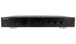

AX-50
STEREO INTEGRATED AMPLIFIER
OPERATING INSTRUCTIONS

CONTENTS
SAFETY INFORMATION ...................................................................................................................2
SAFETY INSTRUCTION .................................................................................................................3-4
REMOTE CONTROL ....................................................................................................................5-6
FRONT & REAR PANEL INFORMATION .............................................................................................7
CONNECTIONS ............................................................................................................................8-9
BASIC OPERATION ..................................................................................................................10-11
TROUBLESHOOTING .....................................................................................................................12
SPECIFICATIONS ...........................................................................................................................13
WARRANTY & SERVICE .................................................................................................................14
SAFETY INFORMATION
Design and specicaons contained within this manual are subject to change without noce.
TO REDUCE THE RISK OF ELECTRIC SHOCK DO NOT REMOVE THE FRONT OR BACK COVER.
THERE ARE NO USER SERVICEABLE PARTS INSIDE. REFER SERVICING TO QUALIFIED SERVICE PERSONNEL.
To prevent electric shock, do not use the polarized AC power plug with an extension cord, receptacle or other outlet unless
the blades can be fully inserted to prevent blade exposure and the potenal risk of electric shock.
CONFORMS TO AUSTRALIAN AND NEW ZEALAND CERTIFICATION STANDARDS
AS/NZS: EN 55013 & EN 301 489-1
ELECTRICAL SAFETY PRODUCT
• To reduce the risk of Electrical Shock, do not re-
move the top or back cover.
• No User Serviceable Parts Inside
• Refer all servicing to qualied service personnel
• Do not expose this appliance to rain or moisture
This lightning bolt with arrow head symbol within an
equilateral triangle is intended to alert the user to the
presence of uninstalled “dangerous voltage” within the
product’s enclosure that may be of sucient magni-
tude to constute the risk of electric shock to persons.
The exclamaon point within an equilateral triangle is
intended to alert the user to the presence of important
operang and maintenance (servicing) instrucons in
the literature accompanying the appliance.
2

SAFETY INSTRUCTIONS
3
• READ AND FOLLOW INSTRUCTIONS: All safety and operaon instrucons should be thoroughly read and understood
before the product is operated. Follow all operaon instrucons within this manual.
• RETAIN INSTRUCTIONS: The safety and operaon instrucons should be retained for future reference.
• HEED WARNINGS: Comply with all warnings on the product and in the operang instrucons.
• CLEANING: Unplug the product from the wall outlet before cleaning. Do not use liquid cleaners or aerosol cleaners.
Use only a damp cloth for cleaning.
• GROUNDING or POLARIZATION: This product may be equipped with a polarized alternang current line plug (a plug
having one blade wider than the other). This plug will t into the power outlet only one way. This is a safety feature.
If you are unable to insert the plug fully into the outlet, try reversing the plug. If the plug should sll fail to t, contact
your electrician since it is likely you have an out of sate wall socket. Never force the plug into the socket.
• POWER SOURCES: This product should be operated only from the type of power source indicated on the rear panel
label. If you are not sure of the type of power supply to your home, consult your product dealer or local power com-
pany. For products intend to be operated from baery power, or other sources, refer to the operaon instrucons.
• ACCESSORIES: Do not place this product on an unstable surface or support. The product may fall, causing serious
injury to a child or adult as well as serious damage to the product. An mounng of the product should follow the
manufacturer’s instrucons and use a mounng accessory recommended by the manufacturer. A product and cart
combinaon should be moved with care. Quick stops, excessive force, and uneven surfaces may cause the product
and cart combinaon to overturn.
• OUTDOOR ANTENNA GROUNDING: If an outside antenna or cable system is connected to the product, be sure
the antenna or cable system is grounded so as to provide some protecon against voltage surges and built-up stac
charges. Correct grounding should always be installed by an electrician.
• POWER-CORD PROTECTION: The power supply cables should be routed so that they are not likely to be walked on
or pinched by items placed upon or against them, paying parcular aenon to cables and plugs and the point where
they exit from the product.
• ACCESSORIES: Do not use any unauthorized accessories as they may cause faults with the unit.
• CONDITIONS REQUIRING SERVICE: Unplug this product from the wall outlet and refer servicing to qualied service
personnel under the following condions:
• If the unit exhibits sudden unusual operaon or unusual display characteriscs.
• If liquid has been spilled inside, or objects have fallen into the unit.
• If the unit has been exposed to rain or water.
• If the unit does not operate normally as per the Instrucon Manual.
• If the unit has been dropped or damaged in any way.
• If the unit exhibits a disnct change in performance.
• OVERLOADING: Do not overload wall outlets or extension cords as this can result in the
risk of re or electric shock. Overloaded AC outlets, extension cords, frayed power cables,
damaged or cracked wire insulaon, and broken plugs are dangerous. They may result in
electric shock or re hazard. Periodically examine the power cable - if its appearance indi-
cates damage or deteriorated receptacles have it replaced by your service technician.
• If the product has been damaged in any way - for example if the power cable or plug is damaged, liquid has
been spilled or objects have fallen inside the product, the product has been exposed to rain or moisture,
does not operate normally or it has been dropped please refer the product to your nearest authorized ser-
vice centre which can be found on our website at www.sherwood-av.com.au
• NOTE: Improper adjustment of other controls may result in damage and may require extensive work to be
carried out by a qualied service technician to restore the product to its normal operaon.
• LIGHTNING: For added protecon for this unit during an electrical storm, or when it is le unaended or
unused for a long period of me, unplug it from the wall power outlet and disconnect the antenna cable
if applicable. This will prevent damage to the unit due to lightning and power line surges during electrical
storms.
• HEAT DISPERSION: Leave at least 10cm or 4 Inches of space between the top, back and sides of the unit and
the wall or other components or furniture to ensure proper venlaon.
• WATER INGRESS: This unit must not be exposed to dripping or splashing of liquids of any kind. Also no ob-
jects lled with liquids such as vases should be placed anywhere near this unit in-case of spillage
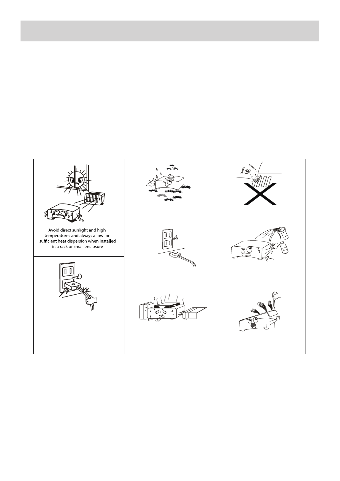
• FURTHER NOTES ON USE:
SAFETY INSTRUCTIONS
Keep the unit free from water,
liquids, moisture and dust
Never allow foreign objects
to fall inside the unit
Unplug the power cord when not
using the unit for long periods of
time, or during electrical storms
Never allow insecticides, benzene, thinners
or other solvents to come into contact
with this unit
Always handle the power cord carefully.
Hold the plug - not the cord when
unplugging and plugging in the cord
Do not obstruct or cover the
ventilation holes or remove the feet
Never disassemble or modify
the unit in any way
4
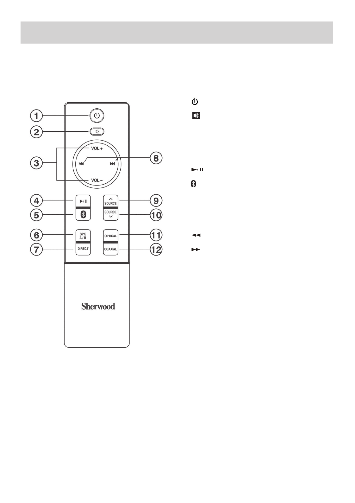
REMOTE CONTROL
5
1. Press to switch the unit between ON/STANDBY mode
2. Press to MUTE the unit. THE Red LED indicator in Speaker
A/B will ash when acvated. Press again to deacvate the
MUTE funcon
3. Press [VOL+/VOL-] to adjust the VOLUME up or down in any
mode
4. Press to Start or Pause Playback in BLUETOOTH mode
5. Press to select BLUETOOTH Input Source
6. Press [SPK A/B] to select SPEAKER Set A. Press again to select
SPEAKER Set B. Press again to select both SPEAKER Sets A+B
7. Press [DIRECT] to select TONE DIRECT mode
8. Press to select the Previous Track in BLUETOOTH mode
8. Press to select the Next Track in BLUETOOTH mode
9. Press [SOURCE ] to select up between Input Sources BT/
DIGITAL/CD/BD/DVD/TUNER/PHONO/LINE IN
10. Press [SOURCE ] to select down between Input Sources
BT/DIGITAL/CD/BD/DVD/TUNER/PHONO/LINE IN
11. Press [OPTICAL] to select Digital OPTICAL Input Source
12. Press [COAXIAL] to select Digital COAXIAL Input Source
^
^
Buon Idencaon:
RM-AX50
REMOTE CONTROL
6
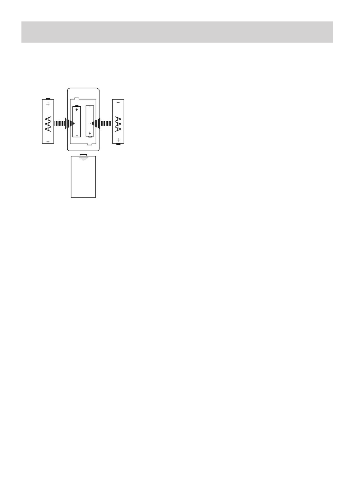
Baery Installaon:
1. Remove the baery compartment cover.
2. Insert two “AAA” dry baeries.
3. Make sure that the baeries are inserted with their
posive “+” and negave “-” poles posioned correctly.
4. Slide closed the cover unl it clicks.
NOTES:
• Even if the remote control unit is operated within the
eecve range, remote control operaon may sll not
be possible if there are any obstacles between the unit
and the remote control.
• If the remote control unit is operated near other appli-
ance which generates infrared rays, or if other remote
control devices using infrared rays are used near the
unit, it may operate incorrectly.
• The power is turned on/o (standby) by pressing the
POWER buon on the remote control unit in standby
mode.
Remote Control Operaon:
By using the provided remote control unit, the receiver can be
controlled from your listening posion.
Use the remote control unit within a range of about 7 meters
(23 feet) and within he angles of up to 30 degrees aiming at
the remote sensor on the front panel of the Amplier.
Precauons Concerning Baeries:
• Be sure to insert the baeries with correct posive+ and
negave – polaries.
• Use baeries of the same type. Never use dierent types
of baeries together.
• Rechargeable and non-rechargeable baeries can be used.
Refer to the precauons on their labels.
• When the remote control unit is not to be used for a long
me (more than a month), remove the baeries from the
remote control unit to prevent them from leaking. If they
leak, wipe away the liquid inside the baery compartment
and replace the baeries with new ones.
• Do not heat or disassemble baeries and never dispose of
old baeries by throwing them in a re.
• If the distance required between the remote control unit
and main unit decreases, the baeries are exhausted. In
this case, replace the baeries with new ones.
7
FRONT & REAR PANEL
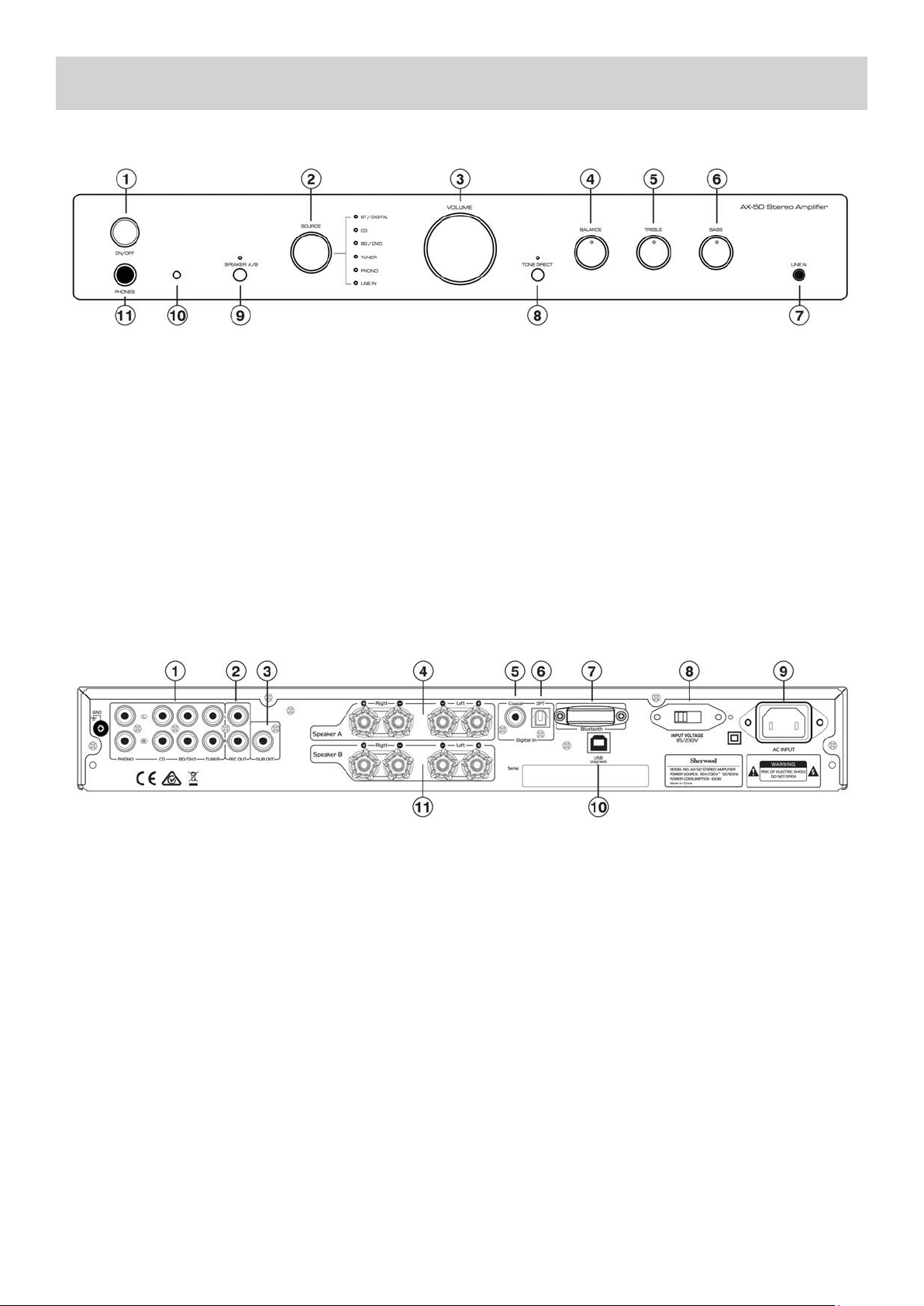
1. ON/OFF: Press to turn the unit either into ON or STAND.
2. SOURCE: Press to select input source (BT, DIGITAL, CD,
BD/DVD, TUNER, PHONO, LINE IN)
TO USE BT/ DIGITAL:
Opcal : LED - Orange color Coaxial : LED - Green color BT :
LED - Red color
3. VOLUME: Controls the volume level of all audio chan-
nels.
4. BALANCE: Use to dial to balance the speaker level from
Le to Right
5. TREBLE: Use this dial for Treble adjustment
6. BASS: Use this dial for Bass adjustment
7. LINE IN: Use to connect LINE IN device
8. TONE DIRECT: Press to select TONE DIRECT mode
9. SPEAKER A/B: Use to select speaker A/B
Speaker A: LED - Green colour
Speaker B: LED - Red colour
Speaker A+B: LED - Orange colour
None: LED - O
10. REMOTE SENSOR: Aim Remote Control at this
11. PHONES: Outputs audio signals for private listening
with headphones
1. ANALOGUE INPUTS: PHONO, CD, BD/DVD, TUNER
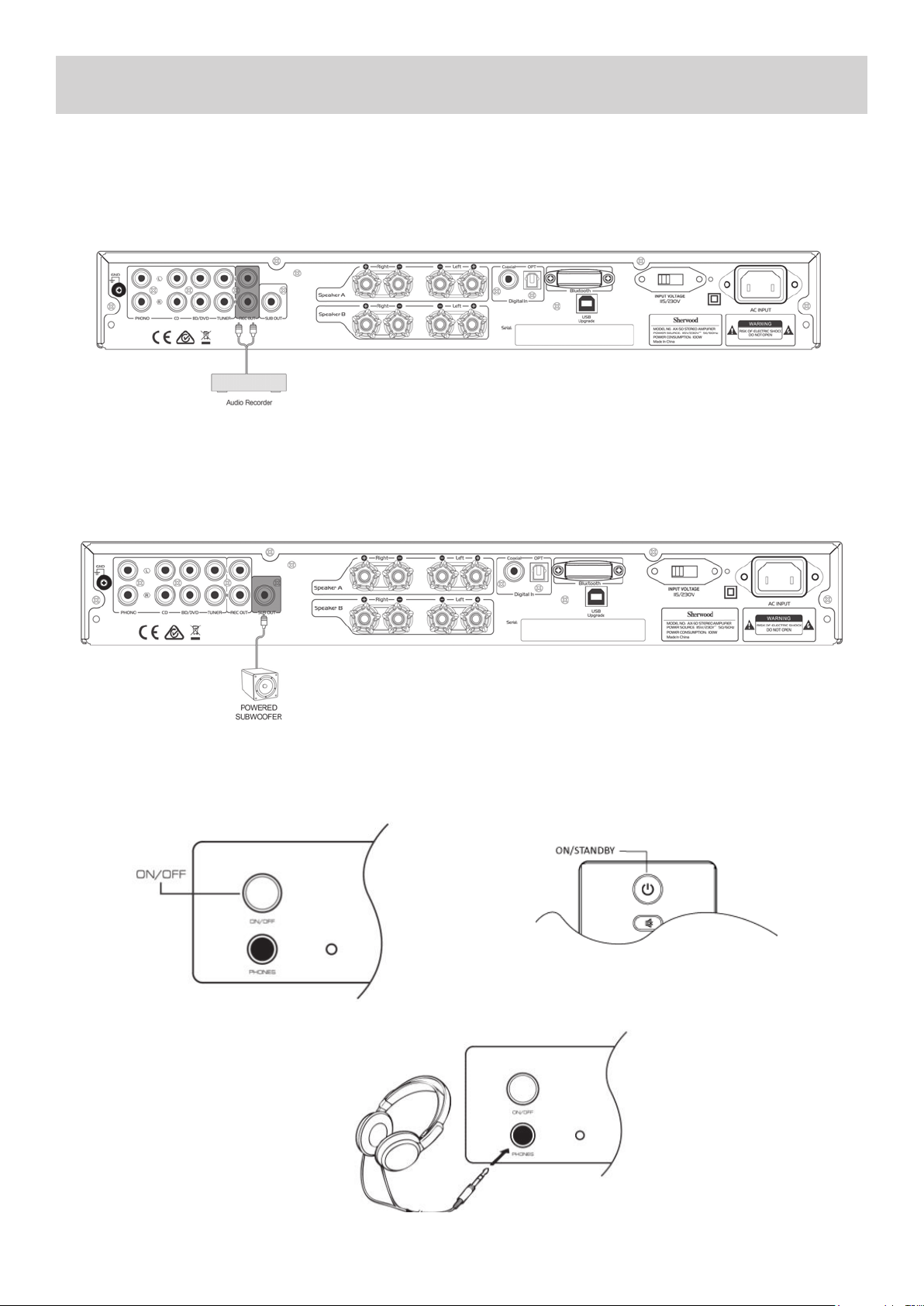
2. REC OUT: This analog audio output is for connecng a
recorder with an analog audio input
3. SUB OUT: This is for connecng an Acve Subwoofer
4. SPEAKER TERMINAL SET A: These terminal posts are for
connecng L/R speakers for Speaker Set A (maximum 1 Pair
5. Coaxial Digital: These coaxial digital audio inputs are for
connecng components with coaxial digital audio out puts,
such as CD and BD/DVD players
6. Opcal Digital: These opcal digital audio inputs are for
connecng components with opcal digital audio outputs,
such as CD and DVD/BD players
7. BLUETOOTH: The Units Bluetooth module (Non Re-
movable)
8. 115/230V: This switch is used to select between 115V
or 230V. FOR AUSTRALIAN AND NEW ZEALAND CUS-
TOMERS - DO NOT CHANGE FROM THE DEFAULT 230V
POSITION
9. AC OUTLET: Socket for connecng the supplied IEC
Mains Power Cord for connecon to mains power
10. USB UPGRADE: For connecon to a PC for upgrad-
ing the units Firmware - For Authorized Service Personnel
use only
11. SPEAKER TERMINAL SET B: These terminal posts are
for connecng L/R speakers for Speaker Set B (maximum
1 Pair)
Rear Panel Connecons:
Front Panel Controls:
8
CONNECTIONS
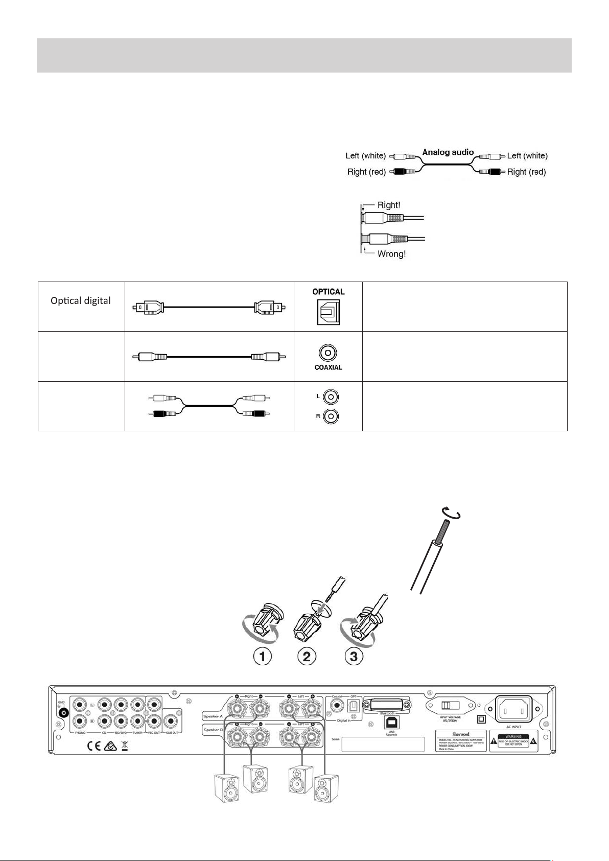
Connecon Color Coding:
RCA-type Audio connecons are usually color-coded: Red and White.
Use Red plugs to connect right-channel audio inputs and outputs
(typically labeled “R”). Use White plugs to connect le-channel audio
inputs and out-puts (typically labeled “L”).
• Push plugs in all the way to make good connecons (loose connec-
ons can cause noise or malfuncons).
• To prevent interference, keep audio and video cables away from
power cords and speaker cables.
Before making any connecons, read the manuals supplied with your other components. Do not connect the power cord
unl you’ve completed and double-checked all connecons.
Cables and Jacks:
audio cable
Coaxial digital
audio cable
Analog audio
cable (RCA)
• Prepare the speaker cables for connecon by stripping o approximately
10 mm or less of the outer insulaon (no more as this could cause a short
circuit). Twist the wires ghtly so that they do not have any frayed or loose
ends.
Loudspeaker Connecons:
• Disconnect the power cord from the wall outlet before making or changing any connecons.
• Check the impedance of your speakers. Only connect speakers with an impedance of 8 ohms or more.
• The amplier’s red speaker terminals are the + (posive) terminals and the black terminals are the – (negave)
terminals. The + side of the speaker cable is marked to make it disnguishable from the – side of the cable. Con-
nect this marked side to the red + terminals and the unmarked side is the black terminal.
Making The Speaker Cable Connecons:
1. Unscrew the Knob
2. Insert the bare speaker cable end through
the hole in the post
3. Tighten down the knob (nger ght only)
to secure the cable
Oers the best sound quality. Can be used to listen to Digital Audio
Formats (Like Dolby Digital or DTS for example) in 2 Channel Stereo
Mode.
NOTE: You must set the output of your DVD player or Digital device
to PCM to use the Opcal Input.
Works the same as Opcal. Oers the best sound quality. Can be
used to listed to Dolby Digital or DTS in 2 Channel Stereo Mode.
NOTE: You must set the output of your DVD player or Digital device
to PCM to use the Opcal Input.
This cable carries a Stereo Analogue Audio Signal. It’s the most
common commecon format for Analogue Audio and can be found
on virtually all A/V components.
• The Red Plug carries the Right Hand Side Audio Channel.
• The White Plug carries the Le Hand Side Audio Channel.
CONNECTIONS
Audio Connecons:
1. Use audio cables to connect the AX-50’s Input jacks to your compable CD player, Turntable, Tuner, DVD Player or other
compable audio playback device.
2. Select the corresponding input source for audio playback.
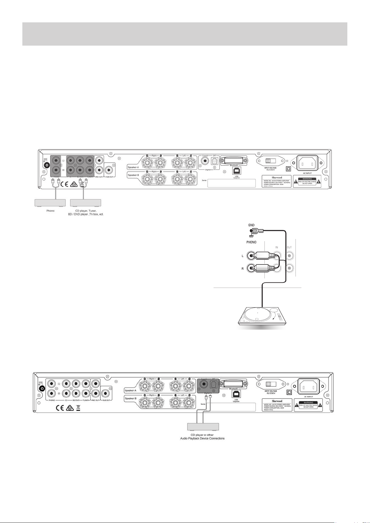
Analogue Audio Connecons:
This unit has four analogue audio input terminals: PHONO, CD, BD/DVD, TUNER.
Note: Do not plug in the mains power lead or turn on the unit before all connecons have been made.
1. Connect to source equipment using Analogue RCA cables (Stereo 2RCA-2RCA):
Digital Audio Connecons:
This unit has two digital audio input connecons: Opcal Digital connecon and Coaxial Digital connecon:
Opcal Input Jacks:
This unit’s opcal digital input jack has a shuer-type cover that opens when an opcal plug is inserted and closes when it’s
removed. Be sure to push plugs in all the way.
Cauon: To prevent shuer damage, hold the opcal plug straight when inserng and removing.
Turntable (PHONO) Connecons:
This unit has one Input designed specically for connecng ONLY to a Turn-
table with MM (Moving Magnet) type cartridge. It has the usual Red and
White RCA Jacks plus an addional Ground wire connecon to reduce noise
interference
1. Connect Turntable using Analogue RCA PHONO Cables (Stereo 2RCA-
2RCA + Ground Wire)
2. Connect Ground wire by unscrewing ‘GND’ terminal on the rear panel
of the AX-50.
3. Slide Ground wire terminal under ‘GND’ post and re-ghten by hand.
Turntable with MM type cartridge
9
BASIC OPERATION
Turning on the Unit:
To turn on the unit, push in the [ON/OFF] buon on the front panel of the unit, OR the [ON/STANDBY] buon on remote control.
Press the [ON/STANDBY] buon again on either the Front Panel or the remote control to put the unit back into Standby mode.
Analogue Audio Output Jacks:
This unit has one pair of Analogue Audio Output Jacks. This output can be used to send a signal of what is currently being lis-
tened to, to an analogue recording device such as a Tape Recorder.
1. Connect to Recording equipment using Analogue RCA cables (Stereo 2RCA-2RCA):
Subwoofer Pre-Out:
This unit has a single Mono Subwoofer Pre-Out Jack, SUB OUT for connecon to an Acve (Powered) Subwoofer. This jack will
output a low frequency signal and it’s level is automacally raised and lowered along with the main Volume control.
1. Connect to an Acve (Powered) Subwoofer using Analogue RCA cable (Mono 1RCA-1RCA):
NOTE: The SUB OUT Jack is constantly acve, and the level is controlled automacally by the main Volume control.
Using Headphones:
Turn the volume down, then connect your
stereo headphones to the [PHONES] jack
on the front panel. You can adjust the
volume by using the VOLUME dial on the
front panel or by pressing the [VOL +/-]
buons on the remote control
10
BASIC OPERATION
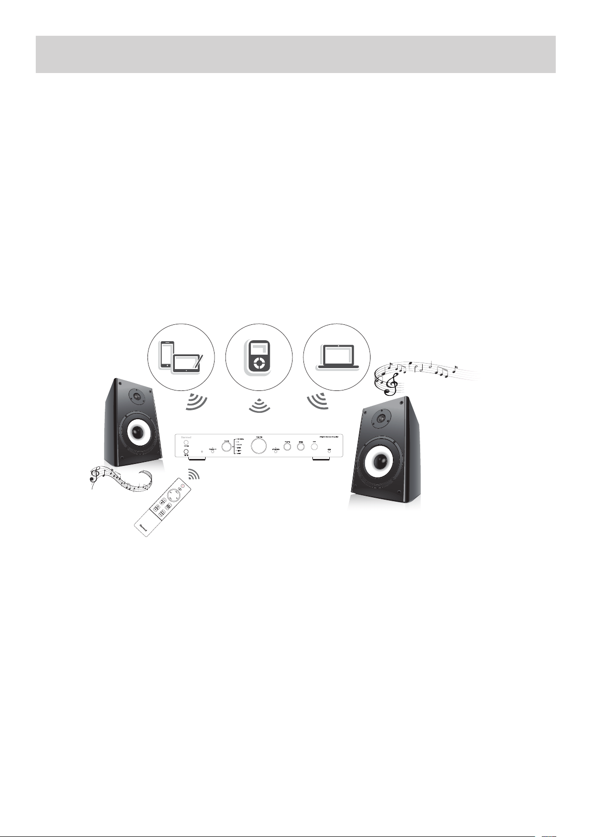
Wireless music play
When the Bluetooth Input is selected on the AX-50, a product equipped with Bluetooth wireless technology (Smartphone, Wire-
less music player, etc.) Can be used to listen to music wirelessly.
• Notes:
Any Bluetooth wireless devices used with the AX-50 must be compable with the A2DP Bluetooth prole. Remote control
operaons cannot be guaranteed for all Bluetooth wireless technology enabled devices.
• Place the portable device near the Main Unit, or within 10 Meters (30 Feet).
Pairing:
1. Turn on the AX-50 and set the Input mode to BLUETOOTH.
2. Open the Bluetooth pairing interface on your portable device.
3. Commence the search supported devices.
4. Select “AX-50” from the found devices list
5. If a PIN Code is required, enter the numbers: “0000”
Note:
• If the last paired device is in range during Bluetooth playback mode, that device will connect automacally.
Input Source Selecon:
Use the INPUT selector dial on the front panel or press the [SOURCE UP/DOWN] buons on the remote control to select your
desired INPUT source.
Volume Adjustment:
Use the VOLUME dial on the front panel or press the [VOL+/-] buons on the remote control to adjust the volume.
Tone Control Sengs:
You can adjust the bass and treble for the front speakers.
BASS: Use this dial to boost or cut low-frequency sounds output by the speakers.
TREBLE: Use this dial to boost or cut high-frequency sounds output by speakers.
TONE DIRECT: Press this buon on the front panel or remote control to defeat the BASS and TREBLE sengs, which will result in
a more neutral sound.
Bluetooth Operaon:
Bluetooth technology is a short-range wireless technology that enables wireless data communicaon between Bluetooth En-
abled digital devices. You can enjoy music wirelessly with a music player featuring Bluetooth wireless technology such
as an MP3 player, mobile phone, etc.
11
LaptopMusic Player
Tablet or
Smartphone
RC-AX50
REMOTE CONTROL OPERATION
BLUETOOTH ENABLED DEVICES
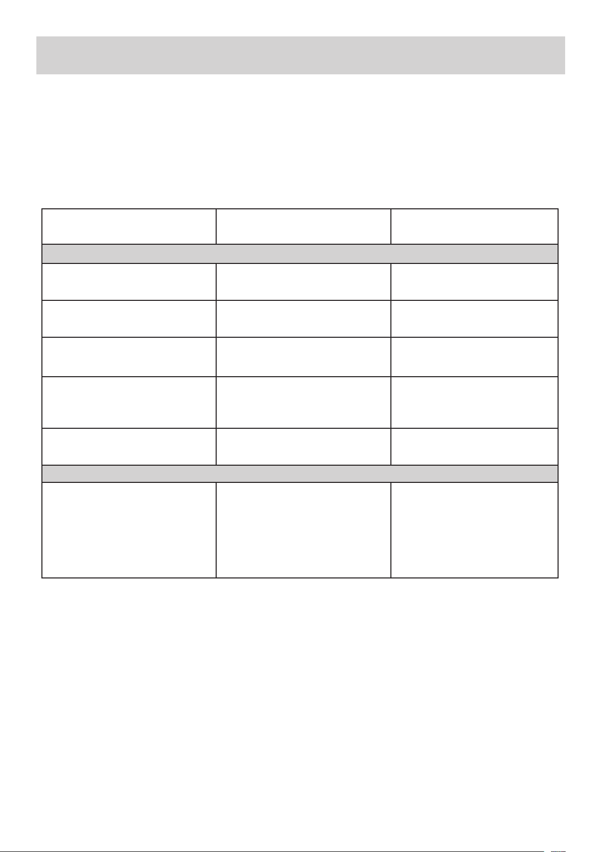
TROUBLESHOOTING
To determine any problem with your receiver, always check the most obvious possible causes rst. If any problems sll remain
aer you have checked the items below please consult your nearest Authorized Dealer or Authorized Sherwood Service Centre.
If you experience any of the following dicules while using the system, use this troubleshoong guide to help remedy the
problem before requesng servicing. Should any problems persist, consult your nearest authorized dealer or authorized Service
Agent.
If the unit does not operate normally due to external inuence such as stac electricity, disconnect the power plug from the wall
outlet and insert again to return to normal operang condions.
PROBLEM POSSIBLE CAUSE REMEDY
Main Amplier:
When listening to the music in stereo.
Le/right speakers reversed.
Speakers are connected incorrectly. Check, and reconnect as required.
Low hum or buzzing sound can be heard
from speakers.
Power cords or lighng placed near this
product.
Place this product away as far as possi-
ble from lighng or power leads.
Sound is only heard from one channel. One of the input cords is disconnected.
Or the BALANCE control is set to one
side.
Connect the input leads and adjust
the BALANCE control to the center
posion.
Sound cuts o when listening or no
sound even though power is ON.
Speaker impedance is less than pre-
scribed for this unit, therefore overload-
ing the Amplier.
Aer turning o the power and then
turning it on again, reduce the vol-
ume or change to the correct 8 ohm
speakers.
Low bass response. Speaker polarity (+/-) is reversed. Check all speakers and speaker wires
for correct polarity.
Remote Control:
Remote control not working • The baeries are exhausted.
• The remote control unit is too far
from the receiver or out of the eec-
ve range.
• There are large obstacles placed
between the remote and the main
unit.
• Replace the baeries.
• Operate within 10m, and 30° of
the remote sensor
• Remove any obstacles, or operate
from another posion.
• Avoid exposing the remote sensor
on the front panel to direct light.
12
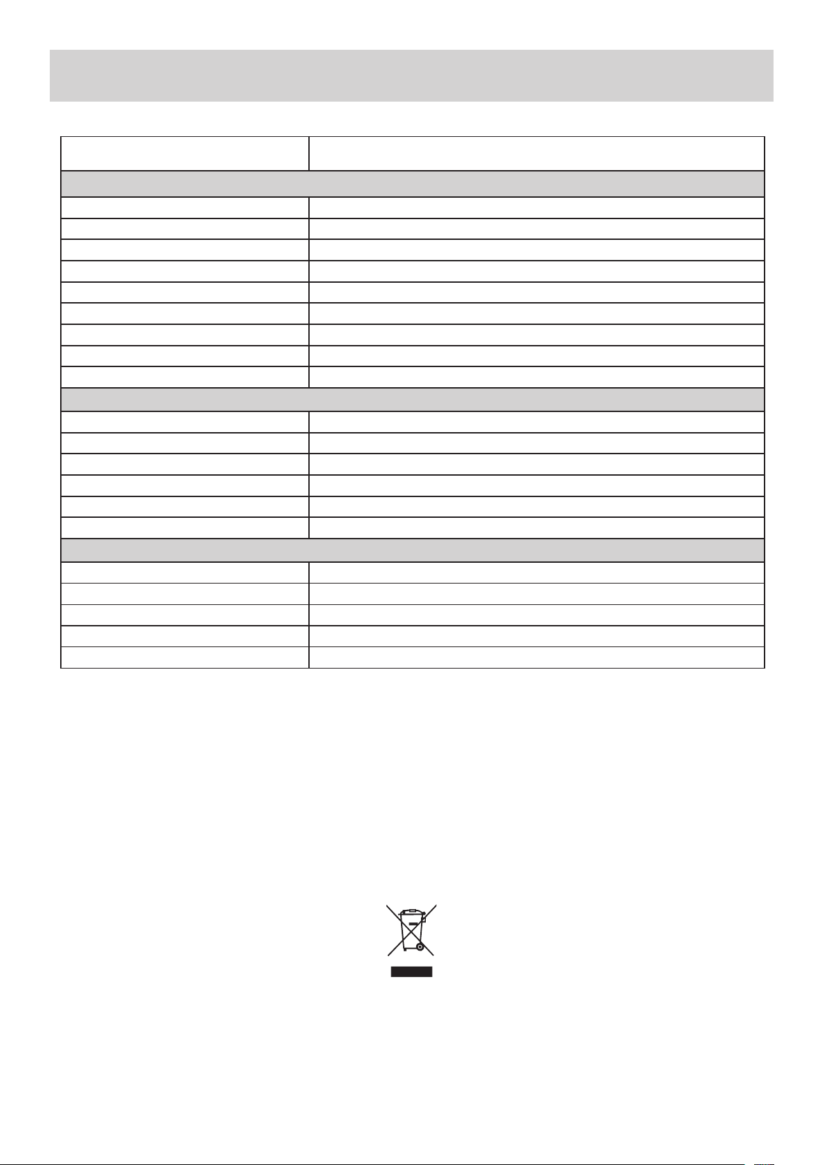
SPECIFICATIONS*
*Design and specicaons are subject to change without noce.
13
ITEM SPECIFICATIONS
Amplier:
Connuous Power Output
50 Was x 2CH (20Hz - 20kHz, <0.07%,
8Ω)
Total Harmonic Distoron < 0.07% @ 1kHz
Frequency Response - Line Inputs 20Hz - 20kHz
Input Sensivity - Line Inputs 200mV
Input Sensivity - Phono Input 2.5mV
Input Overload - Line Inputs 5V
Signal to Noise Rao (IHF “A” Weighted) > 100dB
Channel Separaon - Line Inputs > 85dB
Tone Controls - Bass/Treble 100Hz / 10kHz ±6dB
Bluetooth:
Version V2.1
Receiver Support EDR/ A2DP/AVRCP
Sampling Rate 48K/24Bit
S/N Rao 95dB
Transmission Distance 10 Meters
Frequency Range 2402~2480 MHz
General:
Standby Power Consumpon < 0.5W
Power Requirements - AC AC220V-240V / 50Hz (AUST/NZ) AC115V / 60Hz (USA) SELECTABLE
Power Consumpon 220W Maximum
Dimensions - Main Unit 435mm x 280mm x 70mm (W x D x H)
Weight - Main Unit 6.5Kg
This symbol marked on the product and instrucon manual means that your electrical and electronic
equipment shoule always be disposed of at the end of it’s life separately from your general household waste.

WARRANTY & SERVICE
HOME & DOMESTIC USE LIMITED WARRANTY - AUSTRALIA & NEW ZEALAND
SHERWOOD™ products are engineered and manufactured with pride for excellent performance, value and years of trouble free operaon.
In the unlikely event however that you should have trouble with your SHERWOOD™ product we are pleased to oer this warranty. It is
important that you read the contents of this warranty and be familiar with your rights and obligaons.
Our goods come with guarantees that cannot be excluded under the Australian Consumer Law. You are entled to a replacement or
refund for a major failure and for compensaon for any other reasonably foreseeable loss or damage. You are also entled to have the
goods repaired or replaced if the goods fail to be of acceptable quality and the failure does not amount to a major failure.
The benets of this warranty are in addion to any rights and remedies imposed by Australian State and Federal legislaon that cannot be
excluded. Nothing in this warranty is to be interpreted as excluding, restricng or modifying any State or Federal legislaon applicable to
the supply of goods and services which cannot be excluded, restricted or modied.
Scope Of Warranty:
SHERWOOD™ warrants to the original retail purchaser that we will repair or replace, at our opon, any SHERWOOD™ product which is
found to be defecve in material and/or workmanship for a period of 12 months from the date of purchase. During the warranty period,
an authorized SHERWOOD™ Service Centre will provide both parts and labour free of charge to correct any defect in materials or work-
manship, subject to the warranty terms and condions.
Warranty Terms & Condions:
• This warranty is valid within Australia and New Zealand for SHERWOOD™ products purchased in Australia or New Zealand for domes-
c home use only and where used in accordance with any instrucons provided with or on the product.
• The warranty shall be void if the serial number is removed, defaced or altered in any way.
• You must provide a copy of the original purchase receipt to obtain warranty repairs. We reserve the right to quote for and or charge
for repairs outside the warranty period or where the date of original purchase cannot be veried.
• Warranty repairs must be undertaken by an authorised SHERWOOD™ Service Centre. Visit our web site for the locaon of your near-
est SHERWOOD™ Service Centre at www.sherwood-av.com.au
• No person is authorised to make or give any asserons, statements or undertakings whether expressed or implied about other, or
addional to, the terms of this warranty.
• We reserve the right to make changes or improvements in design or manufacture without any obligaon to change or improve previ-
ously manufactured product. SHERWOOD™ shall not be responsible for incidental and or consequenal damages or loss.
What Is Not Covered:
• The cost of delivery and insurance in transit to the service centre.
• It is your sole responsibility to arrange for your product to be forwarded to your nearest SHERWOOD™ Service Centre for repair or
replacement.
• Time taken to invesgate your warranty claim where the product is found to be in good working order. This includes where you have
not followed instrucons contained in any manuals provided with the product or where the fault is caused by use with incompable
equipment and or soware.
• Warranty repairs where the product has been tampered with, altered, modied or repaired by any unauthorized person/s.
• Misuse, mishandling or abuse to the product including cosmec imperfecons, scratches, Acts of God and or electrical surges.
• Normal wear & tear and maintenance, cleaning, periodic check-ups or charges for installaon, removal or re installaon of the prod-
uct.
• Audio or video data stored on your Smartphone, iPod or similar music storage device and or other devices used with or connected to
your SHERWOOD™ product or media of any type.
When You Need Service:
• If you do require warranty service please visit our web site at www.sherwood-av.com.au for details of any warranty updates and
the locaon of your nearest SHERWOOD™ authorised Service Centre. Alternavely you may contact our oce directly via phone or
e-mail. Contact details can be found at the boom of this page.
• Securely pack and send the product to the SHERWOOD™ authorised Service Centre. DO NOT return any accessories with your prod-
uct unless the accessory is malfunconing.
• We strongly suggest transit insurance as we cannot be responsible for products lost and or damaged when in transit to the Service
Centre.
• Include a clear descripon of the problem you are experiencing with your product and your name, address and dayme contact
details.
This warranty gives you specic legal rights and you may have other rights which vary from locaon to locaon. This limited warranty
does not intend to aect these rights in any way whatsoever.
PROUDLY DISTRIBUTED IN AUSTRALIA BY:
VOLITION AUSTRALIA PTY LTD
20 Corporate Boulevard, Bayswater VIC 3153 Australia
PHONE: 03 9729 9300 / FAX: 03 9729 7900
Web: www.sherwood-av.com.au
Email: service@volion.com.au
PROUDLY DISTRIBUTED IN NEW ZEALAND BY:
THE VOLITION GROUP (NZ) LTD
C\- 20 Corporate Boulevard, Bayswater VIC 3153 Australia
PHONE: 0800 865 484 / FAX: 09 925 1124
Web: www.sherwood-av.co.nz
Email: service@volion.com.au
14

NOTES

AX-50
STEREO INTEGRATED AMPLIFIER
Printed in China
