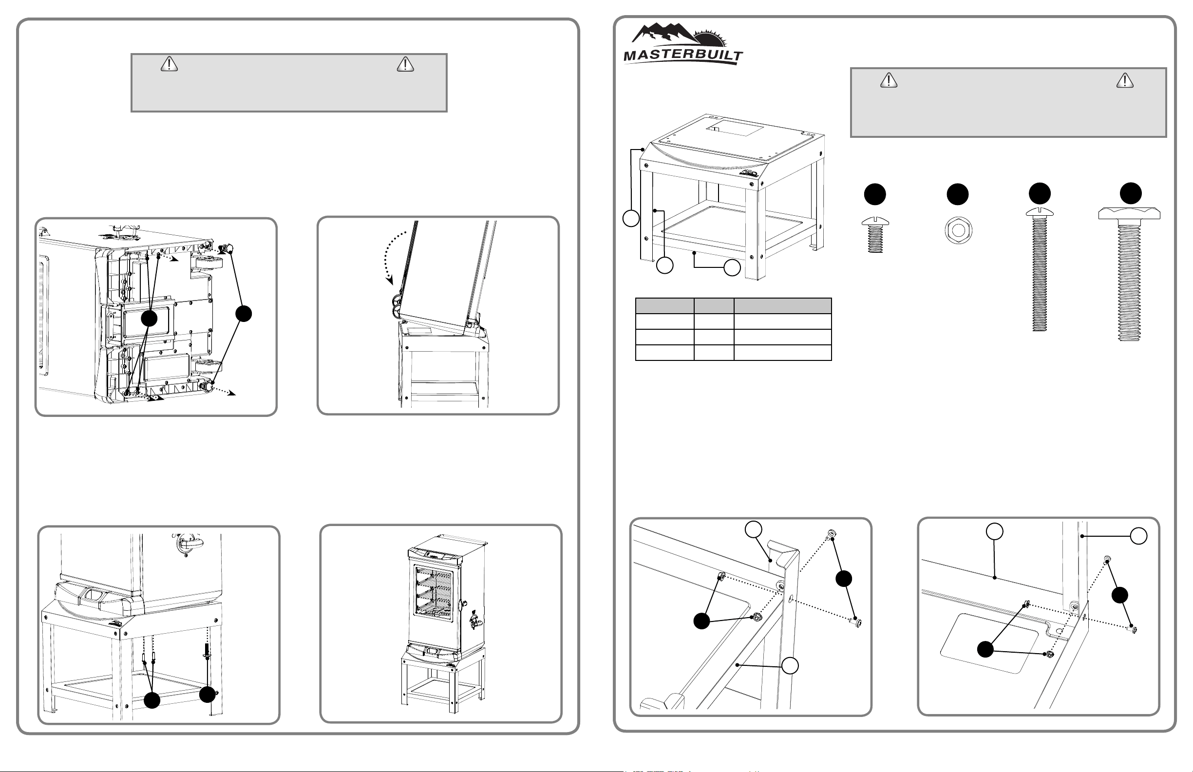
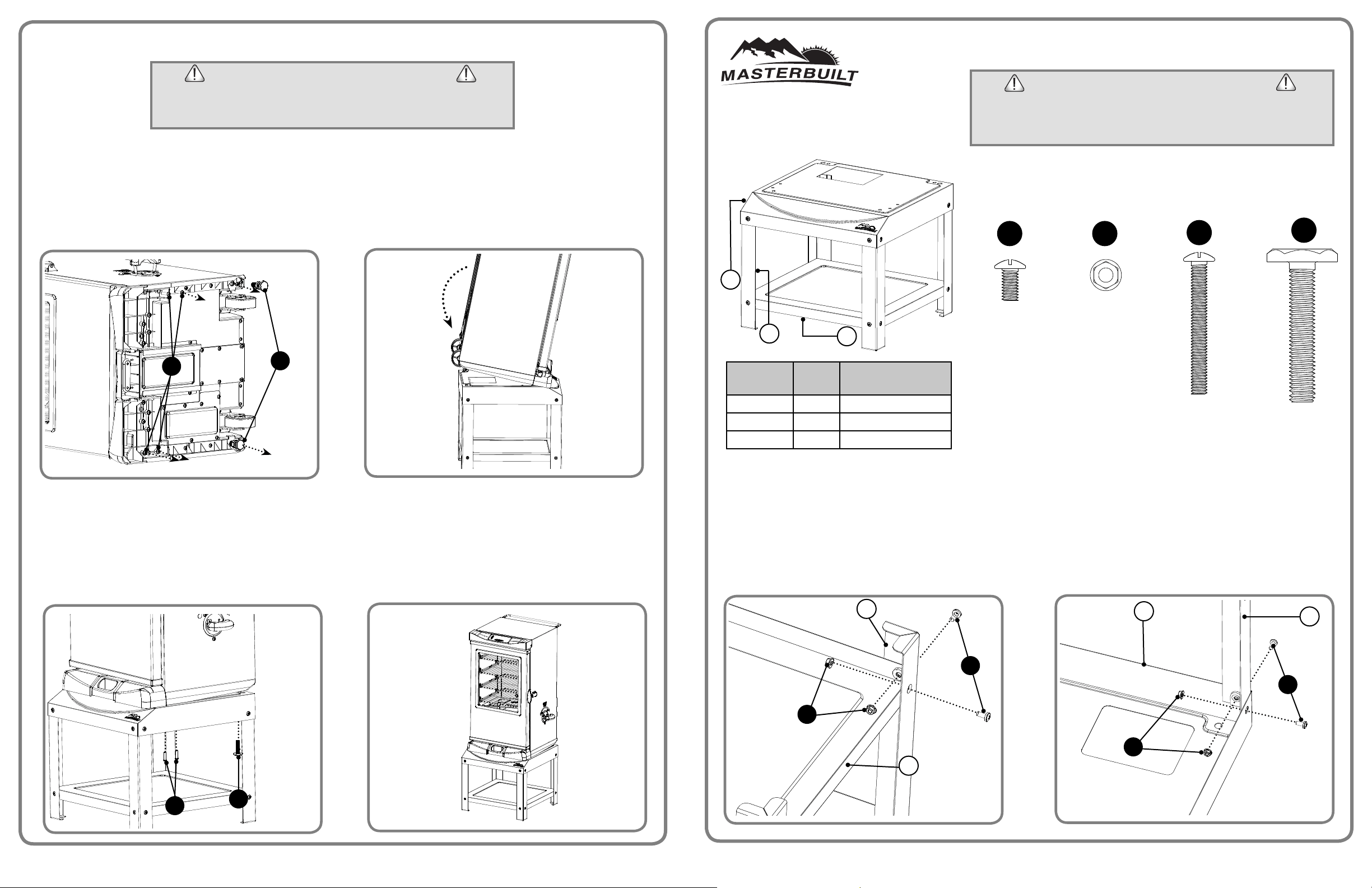
Con cuidado, coloque el ahumador de costado
como se ilustra.
Retire las patas (E) y los tornillos (F).
Nota: Los herrajes (E) y (F) no están en el paquete de
herrajes. Estos vienen con la unidad del ahumador.
Introduzca los tornillos (C) dentro del cuerpo del ahuma-
dor, a través de la parte inferior de la base del ahumador.
Introduzca el tornillo (D) dentro del cuerpo del ahumador,
a través de la parte inferior de la base del ahumador.
Repita el paso del lado opuesto.
Nota: Apriete los tornillos (C) primero, antes de apretar
las patas (D).
Pídale a alguien que lo ayude a levantar y colocar el
ahumador sobre la base, como se muestra abajo.
Apriete todos los herrajes. La instalación está
completa.
1
PASO
3
PASO
2
PASO
4
PASO
INSTALACIÓN DEL AHUMADOR
F
C
E
D
ADVERTENCIA
· NO INTENTE LEVANTAR EL AHUMADOR SIN AYUDA. PÍDALE A ALGUIEN QUE
LO AYUDE ANTES DE EMPEZAR A INSTALAR EL AHUMADOR.
· NO LEVANTE LA UNIDAD POR EL ASA TRASERA.
Masterbuilt Manufacturing, Inc. · 1 Masterbuilt Ct. Columbus, GA 31907 · Servicio al cliente: 1-800-489-1581 · www.masterbuilt.com
ELECTRIC SMOKER STAND
Models 20101113, 20101213
Masterbuilt Manufacturing, Inc. · 1 Masterbuilt Ct. Columbus, GA 31907 · Customer Service: 1-800-489-1581 · www.masterbuilt.com
112712-04SS
MADE IN CHINA
CAUTION
· SMOKER STAND INTENDED FOR USE WITH DESIGNATED MASTERBUILT
SMOKERS ONLY.
· DO NOT SIT ON SMOKER STAND.
· NEVER MOVE SMOKER STAND WHILE IN USE.
1
STEP
2
STEP
1
2
3
PART NO QTY DESCRIPTION
1 1 Tabletop
2 4 Leg
3 1 Bottom Shelf
M6
Flange Nut
Qty. 16
B
Position leg (2) inside tabletop (1) as shown.
Secure leg (2) to tabletop (1) using screws (A)
and nuts (B).
Repeat step for remaining legs.
Tighten all hardware.
2
1
Place bottom shelf (3) inside legs (2) as shown.
Secure bottom shelf (3) to legs (2) using screws (A)
and nuts (B).
Repeat step for remaining legs.
Note: Do not fully tighten hardware.
3
2
DO NOT RETURN TO RETAILER
For Assembly Assistance, Missing or Damaged Parts
Call: MASTERBUILT Customer Service at 1-800-489-1581.
M6 x 50
Screw
Qty. 4
M10 x 55
Screw
Qty. 2
C
D
B
A
B
A
A
M6 x 12
Screw
Qty. 16
Tools needed for assembly (not included): Phillips Head Screw Driver, Adjustable Wrench
For use with the following models:
20070213, 20070312,
20070512, 20070513, 20071214, 20072612 20072712
Carefully position smoker on side as shown.
Remove legs (E) and screws (F).
Note: Hardware (E) and (F) are not in blister pack.
This hardware comes with smoker assembly.
Insert screws (C) up through bottom of smoker stand and
into smoker body.
Insert screw (D) up through bottom of smoker stand and
into smoker body.Repeat step on opposite side.
Note: Tighten screws (C) fi rst, before tightening legs (D).
Get a helper to help lift and position smoker on top
of stand, as shown below.
Tighten all hardware. Installation is complete.
1
STEP
3
STEP
2
STEP
4
STEP
SMOKER INSTALLATION
F
C
E
D
CAUTION
· DO NOT ATTEMPT TO LIFT SMOKER ALONE. GET A HELPER BEFORE
BEGINNING SMOKER INSTALLATION.
· DO NOT LIFT SMOKER BY REAR HANDLE.
Masterbuilt Manufacturing, Inc. · 1 Masterbuilt Ct. Columbus, GA 31907 · Customer Service: 1-800-489-1581 · www.masterbuilt.com
BASE PARA AHUMADOR
ELÉCTRICO
Masterbuilt Manufacturing, Inc. · 1 Masterbuilt Ct. Columbus, GA 31907 · Servicio al cliente: 1-800-489-1581 · www.masterbuilt.com
HECHO EN CHINA
ADVERTENCIA
· BASE PARA AHUMADOR DISEÑADA PARA USO EXCLUSIVO CON AHUMA-
DORES MASTERBUILT.
· NO SE SIENTE SOBRE LA BASE DEL AHUMADOR.
· NUNCA MUEVA LA BASE DEL AHUMADOR MIENTRAS LO ESTÉ USANDO.
1
PASO
2
PASO
1
2
3
PIEZA
No.
CANT. DESCRIPCIÓN
1 1 Tablero
2 4 Pata
3 1 Repisa inferior
Tuerca con brida
M6
Cant.: 16
B
Coloque la pata (2) dentro del tablero
(1) como se ilustra.
Una la pata (2) al tablero (1) con los tornillos
(A) y las tuercas (B).
Repita el paso con las demás patas.
Apriete todos los herrajes.
2
1
Coloque la repisa inferior (3) dentro de las patas
(2) como se ilustra.
Una la repisa inferior (3) a las patas (2) con los
tornillos (A) y las tuercas (B).
Repita el paso con las demás patas.
Nota: No apriete por completo los herrajes.
3
2
NO DEVUELVA EL PRODUCTO AL ESTABLECIMIENTO MINORISTA
Para solicitar ayuda sobre el armado, piezas perdidas o dañadas,
llame al Servicio de atención al cliente de
MASTERBUILT, al 1-800-489-1581
Tornillo
M6 x 50
Cant.: 4
Tornillo
M10 x 55
Cant.: 2
C
D
B
A
B
A
A
Tornillo
M6 x 12
Cant.: 16
Herramientas necesarias para el armado (no incluidas): Destornilllador Phillips, llave ajustable
Modelos: 20101113, 20101213
Para usarse con los siguientes modelos: 20070213, 20070312,
20070512, 20070513, 20071214, 20072612 20072712