This knob allows to set the timer. The numbers indicated are minutes. Adjustment is progressive so that the time can also be set to any intermediate value between these numbers. At the end of the set time, a buzzer will sound but cooking will not be interrupted.
The timer does not stop the cooking operation. It only warns the user that the preset number of minutes has passed.
2.Function selection knob
This knob allows to select different oven functions.
For further information see “8. COOKING WITH THE OVEN”.
When using the grill or the fan-assisted grill, the light comes on to signal that the oven is heating up. When this light goes out, the preset heating temperature has been reached.
3.Gas oven thermostat knob
This knob allows to light the bottom burner inside the oven. The cooking temperature is selected by turning the knob anti-clockwise to the required setting, between MIN and MAX.
For further information see “7.7 Using the bottom burner”.
To switch on the light while the bottom burner is being used, turn the timer knob to symbol .
4.Hob burners control knob
To light the flame, press the knob and turn it anti-clockwise to the maximum flame symbol ( ). To adjust the flame, turn the knob to the zone between the maximum ( ) and the minimum () settings. To turn off the burner, turn the knob to the position. (The adjacent symbol indicates the front left burner).
AVAILABLE ACCESSORIES
NOTE: Some models are not provided with all accessories.
Rack: useful for holding cooking containers.
Oven tray: useful for collecting fat from foods placed on the rack above.
Reduction pan stand: useful when using small pans.
Tray rack: to be placed over the top of the oven tray; for cooking foods which may drip.
Deep oven tray: useful for baking cakes, pizza and oven-baked desserts.
WOK reduction: useful when using a wok.
The oven accessories intended to come into contact with food are made of materials that comply with the provisions of current legislation.
Accessories available on request:
• Original supplied and optional accessories may be ordered from any Authorised Assistance Centre.
• Use only original accessories supplied by the manufacturer.
Using the rack or tray
The racks or trays are equipped with a mechanical safety lock which prevents them from being taken out accidentally. To insert the rack or tray correctly, check that the lock is facing downwards (as shown in the figure at the side).
To remove the rack or tray, lift the front slightly.
The mechanical lock (or the extension piece where present) must always face the back of the oven.
Gently insert racks and trays into the oven until they come to a stop.
In models with guides, clean the trays before using them for the first time. Cleaning will remove any manufacturing residues, which may otherwise scratch the sides of the oven cavity when trays are being inserted.
Using the support rack
The support rack is inserted into the tray (as shown in the figure). Using this, foods can be cooked and the fat can be collected separately from the food which is being cooked.
Using the reduction pan stands
The reduction pan stands should be placed on top of the hob pan stands as shown in the adjacent figure. Make sure they are stable.
The WOK pan stand should only be used when cooking with a wok.
USING THE COOKING HOB
General warnings and advice
Before lighting the hob burners, make sure that the flame-spreader crowns are correctly positioned in their housings with their respective burner caps.
Lighting the hob burners
All the appliance's control and monitoring devices are located together on the front panel. The burner controlled by each knob is shown next to the knob. The appliance is equipped with an electronic lighter. Simply press the knob and turn it anti-clockwise to the maximum flame symbol until the burner lights. If the burner does not light in the first 15 seconds, turn the knob to “0” and wait 60 seconds before trying again. After lighting, keep the knob pressed down for a few seconds to allow the thermocouple to heat up. The burner may go out when the knob is released: in this case, the thermocouple has not heated up sufficiently.
Wait a few moments and repeat the operation, keeping the knob pressed for longer.
If the burners should go out accidentally, a safety device will be tripped, cutting off the gas supply, even if the gas tap is open. In this case, turn the knob to the OFF position and wait at least 60 seconds before trying to light the burner again.
Practical hints for using the hob burners
For better burner efficiency and to minimise gas consumption: use pans with lids and of a suitable size for the burner, so that the flames do not reach up the sides of the pan (see paragraph “6.4 Cookware diameters”). Once the contents come to the boil, turn down the flame far enough to ensure that the liquid does not boil over. If any liquid does boil over or spill, remove the excess from the hob.
To prevent burns or damage to the hob during cooking, all pans or griddles must be placed inside the perimeter of the hob. All pans must have smooth, flat bottoms.
If the flame accidentally goes out, turn off the control knob and wait at least 1 minute before trying to re-light the burner.
Take the greatest care when using fats or oils since they may catch fire if overheated.
Cookware diameters
To prevent damage to the appliance or adjacent units, all pans or griddles must be placed inside the perimeter of the hob.
USING THE OVEN
Before using the appliance
Remove any labels (apart from the technical data plate) from trays, dripping pans and the cooking compartment.
Remove any protective film from the outside or inside of the appliance, including from accessories such as trays, dripping pans, the pizza plate or the base cover.
Before using the appliance for the first time, remove all accessories from the oven compartment and wash them as indicated in “9. CLEANING AND MAINTENANCE”.
Heat the empty appliance to the maximum temperature in order to remove any manufacturing residues which could affect the food with unpleasant odours.
Oven runners
The oven features 5 runners for positioning trays and racks at different heights. The insertion heights are indicated from the bottom upwards (see figure). models with frames models with guides
Storage compartment (on some models only)
The storage compartment is in the bottom of the cooker. It provides storage space for the appliance’s metal accessories and must not be used to store flammable materials, cloths, paper etc.
Do not open the storage compartment when the oven is on and still hot. The temperatures inside it may be very high.
Cooling system
The appliance is equipped with a cooling system which comes into operation as soon as a cooking function starts, with the exception of the gas burner where start-up is delayed. The fan causes a steady outflow of air that exits from the rear of the appliance and which may continue for a brief period of time even after the appliance has been turned off.
Internal light
The light inside the oven comes on when any function is selected, except when the bottom burner is being used, in which case the timer knob must be turned to symbol
General warnings and advice for use
All cooking operations must be carried out with the door closed. The dissipation of heat may cause hazards.
During cooking, do not cover the bottom of the oven with aluminium or tin foil and do not place pans or oven trays on it as this may damage the enamel coating. If you wish to use greaseproof paper, place it so that it will not interfere with the hot air circulation inside the oven.
For the best cooking results, we recommend placing cookware in the centre of the rack.
To prevent any steam in the oven from causing problems, open the door in two stages: keep it half open (5 cm approx.) for 4-5 seconds and then fully open. To access food, always leave the door open as short a time as possible to prevent the temperature in the oven from falling and ruining the food.
To prevent excessive amounts of condensation from forming on the internal glass, hot food should not be left inside the oven for too long after cooking.
While cooking desserts or vegetables, excessive condensation may form on the glass. In order to avoid this, open the door very carefully a couple of times while cooking.
To prevent hazardous overheating, the appliance's lid (where present) must always be raised when using the oven.
Heat the empty appliance to the maximum temperature in order to remove any manufacturing residues which could affect the food with unpleasant odours.
Using the bottom burner
Electronic spark ignition
Open the oven door fully, press the thermostat knob and turn it anti-clockwise between MIN and MAX; the electric spark ignition is activated automatically. After lighting, keep the knob pressed down for a few seconds to allow the thermocouple to heat up. If the burner does not ignite after 15 seconds, stop attempting to light it, leave the oven door open and do not try to light it again for at least 1 minute.
The bottom burner cannot be lit with the oven door closed.
Manual ignition
In the event of a power failure, the oven can be ignited manually. Open the oven door fully, press and turn the thermostat knob anti-clockwise between MIN and MAX; light a long match and put the flame through the centre front slots at the bottom of the oven (as indicated in the figure). Alternatively you can use an electric gas lighter with a long spout. After lighting, keep the knob pressed down for a few seconds to allow the thermocouple to heat up.
If the burner does not ignite after 15 seconds, stop attempting to light it, leave the oven door open and do not try to light it again for at least 1 minute.
If the burner is extinguished accidentally, turn the knob to the off position (0) and wait at least one minute before trying to light it again.
Using the electric grill
Use the function selection knob to select either the grill or the fan-assisted grill. For further information see “8. COOKING WITH THE OVEN”.
Lighting the gas burner will switch off the electric grill element. The bottom burner and the electric grill can never be used at the same time.
Grilling processes must never last more than 60 minutes.
Accessible parts may be very hot during and after use of the grill; keep children well away from the appliance.
COOKING WITH THE OVEN
GRILL:
The heat coming from the grill element gives perfect grilling results above all for thin and medium thickness meat and in combination with the rotisserie (where present) gives the food an even browning at the end of cooking. Perfect for sausages, ribs and bacon. This function enables large quantities of food, particularly meat, to be grilled evenly. (4th or 5th runner).
FAN-ASSISTED GRILL:
The air produced by the fan softens the strong heatwave generated by the grill, grilling perfectly even very thick foods. Perfect for large cuts of meat (e.g. shin of pork). We recommend using the 4th runner.
FAN:
This function is useful for activating ventilation while using the bottom gas burner. The air produced by the fan helps distribute heat evenly inside the oven.
DEFROSTING:
Rapid defrosting is helped by switching on the fan to ensure uniform distribution of air inside the oven. (We recommend using the 1st or 2nd runner).
Cooking advice and instructions
General advice
We recommend preheating the oven before putting food in.
For cooking on several levels, we recommend using a fan-assisted function to achieve uniform cooking at all heights.
In general, it is not possible to shorten cooking times by increasing the temperature (the food could be well-cooked on the outside and undercooked on the inside).
While cooking desserts or vegetables, excessive condensation may form on the glass. In order to avoid this, open the door very carefully a couple of times while cooking.
For rapid preheating use a fan-assisted function, then select the required function.
Advice for cooking meat
Cooking times, especially for meat, vary according to the thickness and quality of the food and to consumer taste.
We recommend using a meat thermometer for meat when roasting it. Alternatively, simply press on the roast with a spoon: if it is hard, it is ready; if not, it needs another few minutes cooking.
Advice for cooking desserts and biscuits
Use dark metal moulds for desserts: they help to absorb the heat better.
The temperature and the cooking duration depend on the quality and consistency of the dough.
Check whether the dessert is cooked right through: at the end of the cooking time, put a toothpick into the highest point of the dessert. If the dough does not stick to the toothpick, the dessert is cooked.
If the dessert collapses when it comes out of the oven, on the next occasion reduce the set temperature by about 10°C, selecting a longer cooking time if necessary.
Advice for defrosting and proving
We recommend positioning frozen foods in a lidless container on the first shelf of the oven.
The food must be defrosted without its wrapping.
Lay out the foodstuffs to be defrosted evenly, not overlapping.
When defrosting meat, we recommend using a rack positioned on the second runner with the food on it and a tray positioned on the first runner. In this way, the liquid from the defrosting food drains away from the food.
The most delicate parts can be covered with aluminium foil.
For successful proving, a container of water should be placed in the bottom of the oven.
Advice for cooking with the Grill and the Fan-assisted grill
Using the Grill function , meat can be grilled even when it is put into the cold oven; preheating is recommended if you wish to change the effect of the cooking.
With the Fan-assisted grill function,however, we recommend that you preheat the oven before grilling.
Cooking information table
The times indicated in the following tables do not include the preheating times and are provided as a guide only
CLEANING AND MAINTENANCE
Do not use steam jets for cleaning the appliance. The steam could reach the electronics, damaging them and causing short-circuits.
WARNING: For your safety, you are advised to wear protective gloves while performing any cleaning or extraordinary maintenance.
Do not use cleaning products containing chlorine, ammonia or bleach on steel parts or parts with metallic finishes on the surface (e.g. anodizing, nickel- or chromium-plating).
We recommend the use of cleaning products distributed by the manufacturer.
Cleaning stainless steel
To keep stainless steel in good condition it should be cleaned regularly after use. Let it cool first.
Ordinary daily cleaning
To clean and preserve stainless steel surfaces, always use only specific products that do not contain abrasives or chlorine-based acids.
How to use: pour the product onto a damp cloth and wipe the surface, rinse thoroughly and dry with a soft cloth or a microfibre cloth.
Food stains or residues
Do not use metallic sponges or sharp scrapers as they will damage the surfaces.
Use ordinary non-abrasive products with the aid of wooden or plastic utensils if necessary. Rinse thoroughly and dry with a soft cloth or a microfibre cloth.
Do not allow residues of sugary foods (such as jam) to set inside the oven. If left to set for too long, they might damage the enamel lining of the oven.
Cleaning the cooking hob parts
Pan stands
Remove the pan stands and clean them with lukewarm water and non-abrasive detergent, making sure to remove any encrustations. Dry them thoroughly and return them to the hob.
Continuous contact between the pan stands and the flame can cause modifications to the enamel over time in those parts exposed to heat. This is a completely natural phenomenon which has no effect on the operation of this component.
Do no wash these parts in a dishwasher.
Burner caps and flame-spreader crowns
The burner caps and flame-spreader crowns can be removed for easier cleaning. Wash them in warm water and non-abrasive detergent making sure to remove any encrustation, then wait until they are perfectly dry.
Refit the flame-spreader crowns, making sure that they are correctly in place with their respective burner caps, and ensuring that the holes A in the flame-spreaders are aligned with the igniters and thermocouples.
Do no wash these parts in a dishwasher.
Igniters and thermocouples
For correct operation, the igniters and thermocouples must always be perfectly clean. Check them frequently and clean them with a damp cloth if necessary. Remove any dry residues with a wooden toothpick or a needle.
Do not use cleaning products containing chlorine, ammonia or bleach on steel parts or parts with metallic finishes on the surface (e.g. anodizing, nickel- or chromium-plating).
Cleaning the oven
For the best oven upkeep, clean it regularly after having allowed it to cool.
Take out all removable parts.
Clean the oven racks with warm water and nonabrasive detergent. Rinse and dry.
For easier cleaning, the door can be removed (see “10.2 Removing the door”).
The oven should be operated at the maximum heat setting for 15/20 minutes after use of specific products, to burn off the residues left inside the oven.
When the operation is complete, damp parts should be dried thoroughly
Removing guide frames (where present)
Removing the guide frames enables the sides to be cleaned more easily. This should be done each time the automatic cleaning cycle is used (on some models only).
To remove the guide frames:
pull the frame towards the inside of the oven to unhook it from its housing A.
Slide it out of the seats at the back B.
When cleaning is complete, repeat the above procedures to put the guide frames back in.
Cleaning the door glazing
The glass in the door should always be kept thoroughly clean. Use absorbent kitchen roll; remove stubborn dirt with a damp sponge and an ordinary detergent.
Do not use abrasive or corrosive detergents to clean the oven's door glass panels (e.g. powder products, spot-removers and wire sponges). Do not use rough or abrasive materials or sharp metal scrapers to clean the oven's glass doors since they may scratch the surface.
Cleaning the door seal
To keep the seal clean, use a non-abrasive sponge and lukewarm water. The seal should be soft and flexible (with the exception of pyrolitic models).
In pyrolitic models, the seal may flatten over time and lose its original shape. To restore it, pinch the seal all the way along. This also helps remove any dirt on the seal.
EXTRAORDINARY MAINTENANCE
The oven requires periodic minor maintenance or replacement of parts subject to wear, such as gaskets, light bulbs, etc. Specific instructions for each operation of this kind are given below.
Before any intervention that requires access to live parts, disconnect the appliance from the power supply.
WARNING: For your safety, you are advised to wear protective gloves while performing any cleaning or extraordinary maintenance.
Replacing the light bulb
If a light bulb needs to be replaced because it is worn or burnt out, remove the guide frames; see “9.5.1
Removing guide frames (where present)”.
Then remove the bulb cover using a tool (e.g. a screwdriver).
Remove the bulb by unscrewing (filament bulbs) or pulling it out (halogen bulbs) in the indicated direction.
Replace the bulb with one of the same type (25W for filament bulbs or 40W for halogen bulbs).
Do not touch halogen bulbs directly with your fingers, wrap them in insulating material.
Removing the door
Open the door completely.
Insert a pin into the hole in the hinge. Repeat for both hinges.
Grasp the door on both sides with both hands, lift it forming an angle of around 30° and remove it.
To reassemble the door, put the hinges in the relevant slots in the oven, making sure that grooved sections ‘C’ are resting completely at the base of the slots. Lower the door and once it is in place remove the pins from the holes in the hinges.
Removing the door seal (not on pyrolitic models)
To permit thorough cleaning of the oven, the door seal may be removed.
There are fasteners on all four sides to attach it to the edge of the oven. Pull the edges of the seal outwards to detach the fasteners. The seal must be replaced when it loses elasticity and hardens.
Removing the internal glass panels
The glass in the door should always be kept thoroughly clean. To facilitate cleaning, it is possible to remove the door (see 10.2 Removing the door) and place it on a canvas, or open it and lock the hinges in order to extract the glass panels. The glass panels of the door can be completely removed by following the instructions provided below.
Warning: before removing the glass panels, make sure that at least one of the door's hinges has been locked in the open position as described in chapter “10.2 Removing the door”. This operation may have to be repeated during the glass removal process if the door is accidentally freed.
Removing the internal glass panel:
Remove the internal glass panel by pulling the rear part gently upwards, following the movement indicated by the arrows (1).
Then pull the front of the glass panel upwards (2).
Doing this detaches the 4 pins attached to the glass from their slots in the oven door.
Removing the middle glass panels:
( pyrolitic models) there are two middle glass panels attached using 4 small locks. Remove the middle panels by lifting them upwards.
(other models) a middle glass panel may be present; if so, remove it by lifting it upwards.
Cleaning:
It is now possible to clean the external glass panel and the panels removed previously. Use absorbent kitchen roll. In case of stubborn dirt, wash with a damp sponge and neutral detergent.
Replacing the glass panels:
Replace the panels in the reverse of the order in which they were removed.
Reposition the internal glass panel, taking care to centre and insert the 4 pins attached to the glass into their slots in the oven door by applying slight pressure.
INSTALLATION
The appliance connection point shall be accessible with the appliance installed.
Clearances above and around domestic appliances
Extract from AS560
REQUIREMENTS
Overhead clearances - (Measurement A) Range hoods and exhaust fans shall be installed in accordance with the manufacturer’s instructions. However, in no case shall the clearance between the highest part of the hob of the cooking appliance and a range hood be less than 600 mm or, for an overhead exhaust fan, 750 mm. Any other downward facing combustible surface less than 600 mm above the highest part of the hob shall be protected for the full width and depth of the cooking surface area in accordance with Clause 5.12.1.2. However, in no case shall this clearance to any surface be less than 450 mm.
Side clearances - (Measurements B & C) Where B, measured from the periphery of the nearest burner to any vertical combustible surface, is less than 200 mm, the surface shall be protected in accordance with Clause 5.12.1.2 to a height C of not less than 150 mm above the hob for the full dimension (width or depth) of the cooking surface area. Where the cooking appliance is fitted with a ‘splashback’, protection of the rear wall is not required.
Additional requirements for Freestanding and Elevated Cooking Appliaces - (Measurements D & E) Where D, the distance from the periphery of the nearest burner to a horizontal combustible surface is less than 200 mm, then E shall be 10 mm or more, or the horizontal surface shall be above the trivet. See insets above.
NOTES
Requirement 3 does not apply to a freestanding or elevated cooking appliance which is designed to prevent flames or the cooking vessels from extending beyond the periphery of the appliance.
The ‘cooking surface area’ is defined as that part of the appliance where cooking normally takes place and does not include those parts of the appliance containing control knobs.
For definition of hob, see Clause 1.4.64.
For definition of trivet, see Clause 1.4.109.
Consideration is to be given to window treatments when located near cooking appliances. See Clause 5.3.4.
Combustion gas discharge
Combustion gases may be discharged by means of hoods connected to a flue with reliable natural draught, or a fan extraction system. An effective extraction system requires careful design by an authorised specialist, and must comply with the regulation distances and positions. After installation, the engineer must issue a certificate of compliance
Gas connection
This appliance is suitable for installation with Natural Gas or ULPG (propane/butane). Refer to page 33 for the relevant burner pressure and appropriate injector sizes. When the appliance is to be connected to Natural Gas then the pressure regulator supplied must be fitted to the gas inlet. A test point (for checking the gas pressure) is supplied either with the regulator or as a separate fitting in the case of ULPG (propane) appliances.
Connection of the appliance to the gas supply must be in accordance with the requirements of AS5601. A %” BSP connector at the inlet is recommended and the gas supply line to the appliance must be of adequate length to allow sufficient withdrawal of appliance for service or disconnection and be:
annealed copper pipe or;
flexible hose according to AS/NZ1869 & be at least Class “B or D”, 10 mm diameter, .
The appliance must be installed with provision to allow the gas to be turned off and disconnected for servicing and removal of the appliance as required from the gas supply. Before the appliance is operated make certain all relevant parts are placed in the correct position.
On completion of the installation, the installer MUST check for gas leaks and test each burner individually for the correct flame. Once all burners have been tested individually, turn all burners on together. Warranty service calls do not cover these adjustments!
To check the operating pressure of the appliance it is recommended at least 2 large size burners are used. Ensure appliance is secured to wall when installation is completed.
N.G. The regulator supplied must be fitted to the ½ BSP thread at the rear of the appliance. An approved manual shut-off valve must be installed. The N.G. regulator must be checked and adjusted to 1.0kPa after installation.
U.L.P.G. Can be connected to the inlet fitting directly. The pressure must be checked to ensure it is operating at 2.75kPa. A separate test point fitting must be installed between the piping & the appliance for the pressure to be checked to ensure it is operating at 2.75kPa.
Installation with flexible hose must be carried out so that the length of the piping does not exceed 1.2 metres when fully extended; make sure that the hoses do not come into contact with moving parts and that they are not crushed in any way.
Connection to liquid gas
Use a pressure regulator and make the connection on the gas cylinder following the guidelines set out in the regulations in force.
Make sure that the supply pressure complies with the values indicated in the paragraph “10.3 Burner and nozzle characteristics tables”.
Room ventilation
The room containing the appliance should have a permanent air supply in accordance with the standards in force. The room where the appliance is installed must have enough air flow needed for the regular combustion of gas and the necessary air change in the room itself. The hob shall be installed in rooms with natural ventilation, as required by Standards regulations AS/NZS5601.
Extraction of the combustion products
The combustion products may be extracted by means of hoods connected to a natural draught chimney whose efficiency is certain or via forced extraction. An efficient extraction system requires precision planning by a specialist qualified in this area and must comply with the positions and distances indicated by the regulations. When the job is complete, the installer must issue a certificate of conformity.
Positioning and levelling the appliance
After making the electrical and/or gas connections, level the appliance on the floor by means of its four adjustable feet.
First insert the front feet and then the rear feet.
The appliance must be properly levelled to ensure better stability. Screw or unscrew the bottom part of the foot until the appliance is stable and level on the floor.
To prevent possible damage to the appliance, we recommend to screw first the front feet and then the rear ones.
Wall mounting brackets (where present)
The fastening system provided must be installed to ensure the appliance is stable. If installed correctly, this system prevents the appliance tipping over.
Use the adjustable feet to level the appliance at the required height.
Measure the distance from the index of the opening to the floor
Use the same height on the wall to drill the holes for fastening the brackets. The distance between the centres of the holes is given in the diagram above.
Before tightening the brackets fully to the wall, check that the index on the brackets is at the same height as the index on the back of the appliance. Position the appliance, taking care that the brackets are correctly inserted.
Wall fixing
Attach the chain to the cooker
Stretch out the chain attached to the cooker horizontally so that the other end touches the wall.
Mark the wall in the position where the hole is to be drilled.
Drill the hole, insert a wall plug and attach the chain.
Once the chain is in position, push the cooker against the wall and reduce the amount of chain links to keep the chain tight to prevent any excess movement
Replacing the hob nozzles
Remove the pan stands, and remove all burner caps and flame-spreader crowns to access the burner casings.
Unscrew the nozzles using a 7 mm socket wrench.
Replace the burner nozzles according to the type of gas to be used (see 12.5 Burner and nozzle characteristics table).
Replace the burners in the correct position.
Replacing the bottom burner's nozzle
Remove all accessories from inside the oven (such as trays, racks etc.).
Lift up the oven base and pull it outwards as shown in the figure.
Unscrew the fastening screws A and B completely.
Move away the lock that secures the thermocouple and igniter fastened by screw A.
Slide the burner outwards until the nozzle is accessible.
Using a 7 mm socket wrench, replace the nozzle, inserting a new nozzle suitable for the type of gas to be used (see “12.5 Burner and nozzle characteristics table”).
Arrangement of burners
Burner
Auxiliary
Semi-rapid
Ultra-rapid (Wok)
Final operations
After replacing the nozzles, reposition the flame-spreader crowns, the burner caps and the pan stands.
Following adjustment to a gas other than the one originally set in the factory, replace the gas setting label fixed to the appliance with the one corresponding to the new gas. The label is inserted inside the nozzle pack (where present).
Adjusting the hob burner minimum setting for city or natural gas
Light the burner and turn it to the minimum position.
Extract the gas tap knob and turn the adjustment screw next to the tap rod (depending on the model) until the correct minimum flame is achieved. Refit the knob and verify that the burner flame is stable (when turning the knob rapidly from the maximum to the minimum position the flame must not go out). Repeat the operation on all the gas taps.
Adjusting the hob burner minimum setting for LPG
In order to adjust the minimum setting with LPG, the screw at the side of the tap rod must be tightened clockwise all the way.
Adjusting the gas oven burner minimum setting
Light the oven burner and keep it at the maximum for 10/15 minutes.
Then turn the knob to the minimum temperature.
Extract the gas tap knob and turn the adjustment screw next to the tap rod depending on the model) until the correct minimum flame is achieved.
Refit the knob and verify that the burner flame is stable (when turning the knob rapidly from the maximum to the minimum position the flame must not go out). This procedure must be carried out while the door is closed.
(Only for adjustment different from LPG) Open and close the door, if the flame goes out the minimum must be increased.
If using LPG, the adjustment screw must be tightened to end of stroke. If using natural or city gas, simply unscrew the adjustment screw by a few turns.
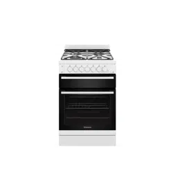
#1 What will the gas plumber usually charge to deliver,install,and take the old one away,its a smeg natural gas free standing oven 60cm?
however this installation is based around your location and this information is available once you place your postcode into the selector on the main page. On the main page place your postcode into: " Your delivery location is:" then select your suburb. Once this is done on the right hand side under installation and accessory options you should see the installers fees which if they cover your area includes: delivery, removal of the old product, installation to current gas and electric supply and removal of all packaging. This model has an electric grill, supplied with a 15 amp plug and leed which your electrician can simply change this to a 10amp plug or hard wire, there is a few options here for your electrical connection.
This unit is designed for usage with Natural Gas. If you require any further info please feel free to contact us on 1300 000 500 any time.
#3 Does this have a 10amp 3 pin plug or will we need an electrician as well as a plumber ?
With the smeg gas upright stove the total electrical required is 8.8amps comes supplied with a normal 10 amp plug and leed.
#4 How long is the electric cord please (supplied for electronics and grill)?
Smeg has advised the electrical cord at the back is around 1m long. If you have any questions, please feel free to contact our customer service team 24 hours a day, 7 days a week. Call us on 1300 000 500.


 ). To adjust the flame, turn the knob to the zone between the maximum (
 ) settings. To turn off the burner, turn the knob to the
  position. (The adjacent symbol indicates the front left burner).


 The storage compartment is in the bottom of the cooker. It provides storage space for the appliance’s metal accessories and must not be used to store flammable materials, cloths, paper etc.


 GRILL:
 FAN-ASSISTED GRILL:
 FAN:
FAN:
 DEFROSTING:
 , meat can be grilled even when it is put into the cold oven; preheating is recommended if you wish to change the effect of the cooking.
 ,however, we recommend that you preheat the oven before grilling.


 Installation with flexible hose must be carried out so that the length of the piping does not exceed 1.2 metres when fully extended; make sure that the hoses do not come into contact with moving parts and that they are not crushed in any way.
 Connection to liquid gas
 Room ventilation
 Extraction of the combustion products