Loading ...
Loading ...
Loading ...
En-5
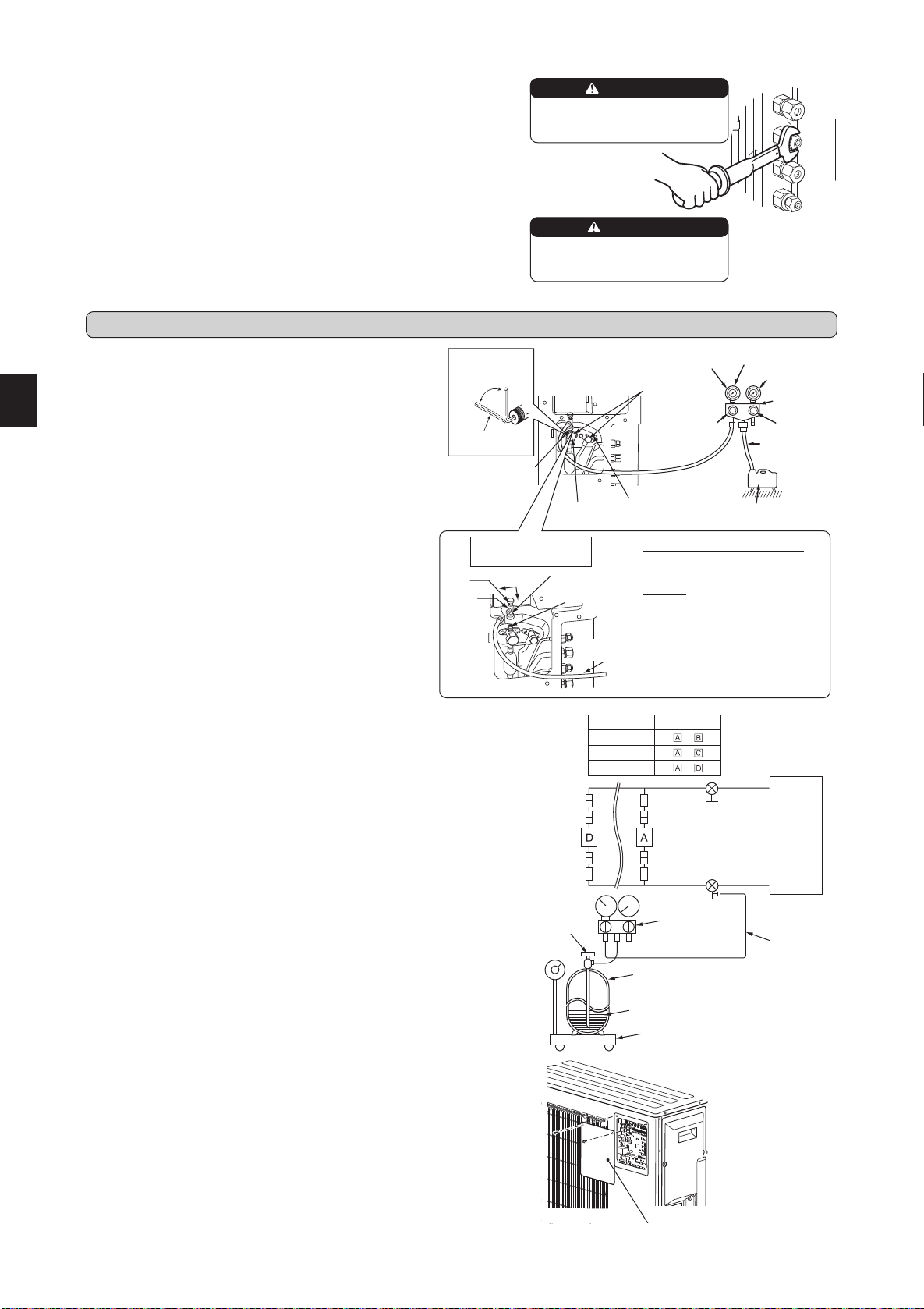
4-1. PURGING PROCEDURES AND LEAK TEST
4-2. GAS CHARGE
Performgaschargetounit.
1)Connectgascylindertotheserviceportofstopvalve.
2)Performairpurgeofthepipe(orhose)comingfromrefrigerantgascylinder.
3)Replenishspeciedamountoftherefrigerant,whileoperatingtheairconditioner
forcooling.
Note:
Incaseofaddingrefrigerant,complywiththequantityspeciedfortherefrigerat-
ingcycle.
CAUTION:
Whenchargingtherefrigerantsystemwithadditionalrefrigerant,besuretouseliquid
refrigerant.Addinggasrefrigerantmaychangethecompositionoftherefrigerantin
thesystemandaffectnormaloperationoftheairconditioner.Also,chargetheliquid
refrigerantslowly,otherwisethecompressorwillbelocked.
Tomaintainthehighpressureofthegascylinder,warmthegascylinderwithwarm
water(under40°C)duringcoldseason.Butneverusenakedreorsteam.
1)Removeserviceportcapofstopvalveonthesideoftheoutdoorunit
gaspipe.(Thestopvalvesarefullyclosedandcoveredincapsin
theirinitialstate.)
2)Connectgaugemanifoldvalveandvacuumpumptoserviceportof
stopvalveonthegaspipesideoftheoutdoorunit.
3)Runthevacuumpump.(Vacuumizeformorethan15minutes.)
4)Checkthevacuumwithgaugemanifoldvalve,thenclosegauge
manifoldvalve,andstopthevacuumpump.
5)Leaveasitisforoneortwominutes.Makesurethepointerofgauge
manifoldvalveremainsinthesameposition.Conrmthatpressure
gaugeshows-0.101MPa[Gauge](-760mmHg).
6)Removegaugemanifoldvalvequicklyfromserviceportofstopvalve.
7)
Fullyopenallstopvalvesonthegaspipeandtheliquidpipe.Operating
withoutfullyopeninglowerstheperformanceandthiscausestrouble.
8)Referto1-2.,andchargetheprescribedamountofrefrigerantif
needed.Besuretochargeslowlywithliquidrefrigerant.Otherwise,
compositionoftherefrigerantinthesystemmaybechangedand
affectperformanceoftheairconditioner.
9)Tightencapofserviceporttoobtaintheinitialstatus.
10
)Leaktest
Union
Stop valve
Liquid
pipe
Indoor
unit
Stop valve with
service port
Gas
pipe
Outdoor
unit
Union
Union
Union
Model Indoor unit
MXZ-2E
–
MXZ-3E
–
MXZ-4E
–
Refrigerantgas
cylinder
operatingvalve
(forR410A)
Gaugemanifold
valve(forR410A)
Chargehose
(forR410A)
RefrigerantgascylinderforR410Awithsiphon
Electronicscaleforrefrigerantcharging
Refrigerant(liquid)
Stopvalve
forGAS
Stopvalvecap
(Torque19.6to
29.4N•m,200
to300kgf•cm)
Gaugemanifold
valve(forR410A)
Compoundpressure
gauge(forR410A)
–0.101MPa
(–760mmHg)
Handle
Low
HandleHigh
Vacuumpump
(forR410A)
*Close
*Open
Hexagonalwrench
*4to5turns
Stopvalve
forLIQUID
Pressuregauge
(forR410A)
Precautionswhenus-
ingthecontrolvalve
Whenattachingthecontrolvalve
totheserviceport,valvecoremay
deformorloosenifexcesspres-
sureisapplied.Thismaycause
gasleak.
Serviceport
Chargehose
(forR410A)
Body
Close
Open
Control
valve
A
Whenattachingthecontrolvalveto
theserviceport,makesurethatthe
valvecoreisinclosedposition,and
then tighten part A. Do not tighten
partA orturnthe bodywhen valve
coreisinopenposition.
Serviceportcap
(Torque13.7to
17.7N•m,140to
180kgf•cm)
Chargehose
(forR410A)
4-3. REMOVING THE MAINTENANCE PANEL
ThesettingofDipSwitchontheoutdoorcontrollerboardcanbechangedwithout
removingthefrontpanel.
FollowtheproceduresbelowtoremovethemaintenancepanelandsettheDip
Switch.
1)Removescrew(s)whichxthemaintenancepanel.
2)Removethemaintenancepanel,andperformnecessarysettings.
3)Installthemaintenancepanel.
Note:
Makesuretoxthemaintenancepanelsecurely.Incompleteinstallationcould
causemalfunction.
Maintenancepanel
4. PURGING PROCEDURES, LEAK TEST, AND TEST RUN
3-2. PIPE CONNECTION
1)Applyathincoatofrefrigerationoil(G)tothearedendsofthepipesandthepipecon-
nectionsoftheoutdoorunit.Donotapplyrefrigerationoilonscrewthreads.Excessive
tighteningtorquewillresultindamageonthescrew.
2)Alignthecenterofthepipewiththatofthepipeconnectionsoftheoutdoorunit,thenhand
tightenthearenut3to4turns.
3)Tightenthearenutwithatorquewrenchasspeciedinthetable.
•Over-tighteningmaycausedamagetothearenut,resultinginrefrigerantleakage.
•Besuretowrapinsulationaroundthepiping.Directcontactwiththebarepipingmay
resultinburnsorfrostbite.
3-3. INSULATION AND TAPING
1)Coverpipingjointswithpipecover.
2)Foroutdoorunitside,surelyinsulateeverypipingincludingvalves.
3)Usingpipingtape(E),applytapingstartingfromtheentryofoutdoorunit.
• Stoptheendofpipingtape(E)withtape(withadhesiveagentattached).
•
Whenpipinghavetobearrangedthroughaboveceiling,closetorwherethetemperature
andhumidityarehigh,windadditionalcommerciallysoldinsulationtopreventcondensation.
When installing the unit, securely
connect the refrigerant pipes before
starting the compressor.
When there are the ports which are
not used, make sure their nuts are
tightened securely.
WARNING
CAUTION
BN79A289H01_en.indd 5 2016/04/20 14:53:01
Loading ...
Loading ...