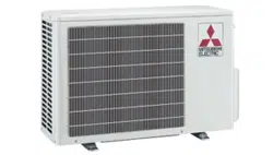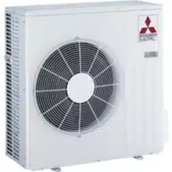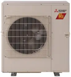
Split-type Air-Conditioner
MXZ-2E52VAD
MXZ-3E54VAD
MXZ-4E71VAD
English
Installation Manual
For INSTALLER
• This manual only describes the installation of outdoor unit.
When installing the indoor unit, refer to the installation manual of indoor unit.
BN79A289H01_cover.indd 1 2016/04/07 16:27:46
En-1
1-1. THE FOLLOWING SHOULD ALWAYS BE OBSERVED FOR SAFETY
• Besuretoread“THEFOLLOWINGSHOULDALWAYSBEOBSERVEDFORSAFETY”beforeinstallingtheairconditioner.
• Besuretoobservethewarningsandcautionsspeciedhereastheyincludeimportantitemsrelatedtosafety.
• Afterreadingthismanual,besuretokeepittogetherwiththeOPERATINGINSTRUCTIONSforfuturereference.
• EquipmentcomplyingwithIEC/EN61000-3-12.
1-2. SPECIFICATIONS
CAUTION
(Couldleadtoseriousinjuryinparticularenvironmentswhenoperatedincorrectly.)
n Do not install the unit by yourself (user).
Incompleteinstallationcouldcausereorelectricshock,injuryduetotheunit
falling,orleakageofwater.Consultthedealerfromwhomyoupurchased
theunitoraqualiedinstaller.
n Perform the installation securely referring to the installation manual.
Incompleteinstallationcouldcause re,electricshock, injuryduetothe
unitfalling,orleakageofwater.
n When installing the unit, use appropriate protective equipment and
tools for safety.
Failuretodosocouldcauseinjury.
n Install the unit securely in a place which can bear the weight of the
unit.
Iftheinstallationlocationcannotbeartheweightoftheunit,theunitcould
fallcausinginjury.
n Electrical work should be performed by a qualied, experienced electri-
cian, according to the installation manual. Be sure to use an exclusive
circuit. Do not connect other electrical appliances to the circuit.
If the capacity of the power circuit is insufcient or there is incomplete
electricalwork,itcouldresultinareoranelectricshock.
n Do not damage the wires by applying excessive pressure with parts
or screws.
Damagedwirescouldcausereorelectricshock.
n Be sure to cut off the main power in case of setting up the indoor P.C.
board or wiring works.
Failuretodosocouldcauseelectricshock.
n Use the specied wires to connect the indoor and outdoor units
securely and attach the wires rmly to the terminal block connecting
sections so the stress of the wires is not applied to the sections. Do
not extend the wires, or use intermediate connection.
Incompleteconnectingandsecuringcouldcausere.
n Do not install the unit in a place where inammable gas may leak.
Ifgasleaksandaccumulatesintheareaaroundtheunit,itcouldcausean
explosion.
n Do not use intermediate connection of the power cord or the extension
cord and do not connect many devices to one AC outlet.
Itcouldcauseareoranelectricshockduetodefectivecontact,defective
insulation,exceedingthepermissiblecurrent,etc.
n Be sure to use the parts provided or specied parts for the installation
work.
Theuseofdefectivepartscouldcauseaninjuryorleakageofwaterdue
toare,anelectricshock,theunitfalling,etc.
n When plugging the power supply plug into the outlet, make sure that
there is no dust, clogging, or loose parts in both the outlet and the
plug. Make sure that the power supply plug is pushed completely into
the outlet.
Ifthereisdust,clogging,orloosepartsonthepowersupplyplugorthe
outlet,itcouldcauseelectricshockorre.Ifloosepartsarefoundonthe
powersupplyplug,replaceit.
n Attach the electrical cover to the indoor unit and the service panel
to the outdoor unit securely.
Iftheelectricalcoveroftheindoorunitand/ortheservicepanelofthe
outdoorunitarenotattachedsecurely,itcouldresultinareoranelectric
shockduetodust,water,etc.
n When installing, relocating, or servicing the unit, make sure that no
substance other than the specied refrigerant (R410A) enters the
refrigerant circuit.
Anypresenceofforeignsubstancesuchasaircancauseabnormalpres-
sureriseandmayresultinexplosionorinjury.Theuseofanyrefrigerant
otherthan that specied for thesystem will cause mechanical failure,
systemmalfunction,orunitbreakdown.Intheworstcase,thiscouldlead
toaseriousimpedimenttosecuringproductsafety.
n Do not discharge the refrigerant into the atmosphere. If refrigerant
leaks during installation, ventilate the room.
Ifrefrigerantcomesincontactwithare,harmfulgascouldbegenerated.
n Check that the refrigerant gas does not leak after installation has
been completed.
Ifrefrigerantgasleaksindoors,andcomesintocontactwiththeameofa
fanheater,spaceheater,stove,etc.,harmfulsubstanceswillbegenerated.
n Use appropriate tools and piping materials for installation.
ThepressureofR410Ais1.6timesmorethanR22.Notusingappropriate
toolsormaterialsandincompleteinstallationcouldcausethe pipesto
burstorinjury.
n When pumping down the refrigerant, stop the compressor before
disconnecting the refrigerant pipes.
Iftherefrigerantpipesaredisconnectedwhilethecompressorisrunning
andthestopvalveisopen,aircouldbedrawninandthepressureinthe
refrigerationcyclecouldbecomeabnormallyhigh.Thiscouldcausethe
pipestoburstorinjury.
n When installing the unit, securely connect the refrigerant pipes
before starting the compressor.
Ifthecompressorisstartedbeforetherefrigerantpipesareconnected
andwhenthestopvalveisopen,aircouldbedrawninandthepressure
intherefrigerationcyclecouldbecomeabnormallyhigh.Thiscouldcause
thepipestoburstorinjury.
n Fasten a are nut with a torque wrench as specied in this manual.
Iffastenedtootight,aarenutmaybreakafteralongperiodandcause
refrigerantleakage.
n The unit shall be installed in accordance with national wiring regula-
tions.
n Earth the unit correctly.
Donotconnecttheearthtoagaspipe,waterpipe,lightningrodortel-
ephoneearth.Defectiveearthingcouldcauseelectricshock.
n Be sure to install an earth leakage breaker.
Failuretoinstallanearthleakagebreakermayresultinelectricshockorre.
n Perform the drainage/piping work securely according to the installation
manual.
Ifthereisdefectinthedrainage/pipingwork,watercoulddropfromtheunit,
soakinganddamaginghouseholdgoods.
n Do not touch the air inlet or the aluminum ns of the outdoor unit.
Thiscouldcauseinjury.
n Do not install the outdoor unit where small animals may live.
Ifsmallanimalsenterandtouchtheelectricpartsinsidetheunit,itcould
causeamalfunction,smokeemission,orre.Also,adviseusertokeep
theareaaroundtheunitclean.
WARNING
(Couldleadtodeath,seriousinjury,etc.)
Required Tools for Installation
Phillipsscrewdriver
Level
Scale
Utilityknifeorscissors
Torquewrench
Wrench(orspanner)
4mmhexagonalwrench
FlaretoolforR410A
GaugemanifoldforR410A
VacuumpumpforR410A
ChargehoseforR410A
Pipecutterwithreamer
ENGLISH
CONTENTS
1.BEFOREINSTALLATION............................................................ 1
2.OUTDOORUNITINSTALLATION...............................................4
3.FLARINGWORKANDPIPECONNECTION............................... 4
4.PURGINGPROCEDURES,LEAKTEST,ANDTESTRUN......... 5
5.PUMPINGDOWN........................................................................ 6
Model
Powersupply*1 Wirespecications*2 Pipelengthandheightdifference
*3,*4,*5,*6,*7,*8
Rated
Voltage
Fre-
quency
Breaker
capacity
Powersupply
Indoor/outdoor
connecting
wire
Max.pipelength
perindoorunit/for
multi-system
Max.height
difference*9
Max.no.ofbends
perindoorunit/
formultisystem
Refrigerant
adjustment
A*10
MXZ-2E52VAD
230V 50Hz
15A
3-core2.5mm
2
4-core
1.0/1.5mm
2
20m/40m
15m
20/40
20g/mMXZ-3E54VAD
25A
25m/50m 25/50
MXZ-4E71VAD 25m/60m 25/60
1. BEFORE INSTALLATION
Note:
WhenconnectingtheMFZ-KJseriesindoorunit(s)tothisoutdoorunit,chargeadditionalrefrigerantaccordingtotheinstructionsinthetablebelow.
No.ofMFZ-KJindoorunits
Pipelength(L)
40morless Morethan40m
1unit 100gadditional(Total2800g) 100g+{(L-40)mx20g/m)}
2units 200gadditional(Total2900g) 200g+{(L-40)mx20g/m)}
3units 300gadditional(Total3000g) 300g+{(L-40)mx20g/m)}
4units 400gadditional(Total3100g) 400g+{(L-40)mx20g/m)}
BN79A289H01_en.indd 1 2016/04/20 14:52:57
En-2
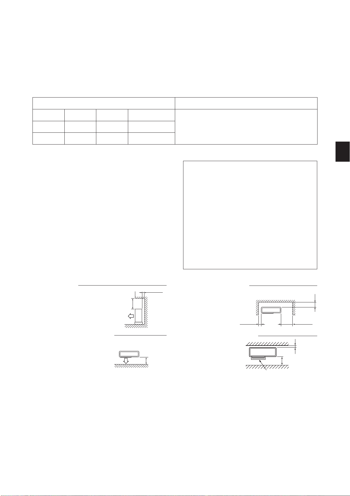
3. Obstacles in front (blowing) only
Whenthereisanobstacleinfrontof
theunitasshowninthegure,open
spaceabove,behind,andonthesides
oftheunitisrequired.
2. Front (blowing) side open
As long as space indicated
in the figure is provided, it
is allowed to install the unit
where obstacles are behind
andon the sides of theunit.
(Noobstacleabovetheunit)
1-3. SELECTING OPTIONAL DIFFERENT-DIAMETER JOINTS
Ifthediameterofconnectionpipedoesnotmatchtheportsizeofoutdoorunit,useoptionaldifferent-diameterjointsaccordingtothefollowingtable.
Portsizeofoutdoorunit
Optionaldifferent-diameterjoints
(portsizeofoutdoorunit→diameterofconnectionpipe)
MXZ-2E52VAD MXZ-3E54VAD MXZ-4E71VAD Liquid/Gas
6.35(1/4)
→
9.52(3/8):PAC-493PI
9.52(3/8)
→
12.7(1/2):MAC-A454JP
9.52(3/8)
→
15.88(5/8):PAC-SG76RJ
12.7(1/2)
→
9.52(3/8):MAC-A455JP
12.7(1/2)
→
15.88(5/8):MAC-A456JP
Refertotheinstallationmanualofindoorunitforthediameterofconnection
pipeofindoorunit.
— — AUNIT 6.35(1/4)/12.7(1/2)
A-BUNIT A-CUNIT B-DUNIT 6.35(1/4)/9.52(3/8)
*1 Connecttothepowerswitchwhichhasagapof3mmormorewhenopen
tointerruptthesourcepowerphase.(Whenthepowerswitchisshutoff,it
mustinterruptallphases.)
*2 Usewiresinconformitywithdesign60245IEC57.Usetheindoor/outdoor
connectingwireinconformitywiththewirespecicationsspeciedinthe
installationmanualoftheindoorunit.
*3 Neverusepipeswiththicknesslessthanspecied.Thepressureresistance
willbeinsufcient.
*4 Useacopperpipeoracopper-alloyseamlesspipe.
*5 Becarefulnottocrushorbendthepipeduringpipebending.
*6 Refrigerantpipebendingradiusmustbe100mmormore.
*7 Insulationmaterial:Heatresistingfoamplastic0.045specicgravity
*8 Besuretousetheinsulationofspeciedthickness.Excessivethickness
maycauseincorrectinstallationoftheindoorunitandinsufcientthickness
maycausedewdrippage.
*
9
Iftheoutdoorunitisinstalledhigherthantheindoorunit,max.height
differenceisreducedto10m.
*
10
Ifpipelengthexceeds40m,additionalrefrigerant(R410A)chargeisre-
quired.(Noadditionalchargeisrequiredforpipelengthlessthan40m.)
Additionalrefrigerant=A×(pipelength(m)-40)
FREE SPACE REQUIRED AROUND OUTDOOR UNIT
1-4. SELECTING THE INSTALLATION LOCATION
• Whereitisnotexposedtostrongwind.
• Whereairowisgoodanddustless.
• Whererainordirectsunshinecanbeavoidedasmuchaspossible.
• Whereneighboursarenotannoyedbyoperationsoundorhotair.
• Whererigidwallorsupportisavailabletopreventtheincreaseofopera-
tionsoundorvibration.
• Wherethereisnoriskofcombustiblegasleakage.
• Wheninstallingtheunit,besuretosecuretheunitlegs.
• Whereitisatleast3mawayfromtheantennaofTVsetorradio.Opera-
tionoftheairconditionermayinterferewithradioorTVreceptioninareas
wherereceptionisweak.Anampliermayberequiredfortheaffected
device.
• Installtheunithorizontally.
• Pleaseinstallitinanareanotaffectedbysnowfallorblowingsnow.In
areaswithheavysnow,pleaseinstallacanopy,apedestaland/orsome
bafeboards.
Note:
Itis advisable to make a piping loopnear outdoor unit so as to reduce
vibrationtransmittedfromthere.
Note:
Whenoperatingtheairconditionerinlowoutsidetemperature,besure
tofollowtheinstructionsdescribedbelow.
• Neverinstalltheoutdoorunitinaplacewhereitsairinlet/outletside
maybeexposeddirectlytowind.
• Topreventexposuretowind,installtheoutdoorunitwithitsairinlet
sidefacingthewall.
•
Topreventexposuretowind,itisrecommendedtoinstallabafe
boardontheairoutletsideoftheoutdoorunit.
Avoidthefollowingplacesforinstallationwhereairconditionertrouble
isliabletooccur.
• Whereammablegascouldleak.
• Wherethereismuchmachineoil.
• Whereoilissplashedorwheretheareaislledwithoilysmoke
(suchascookingareasandfactories,inwhichthepropertiesof
plasticcouldbechangedanddamaged).
• Saltyplacessuchastheseaside.
• Wheresuldegasisgeneratedsuchashotspring,sewage,waste
water.
• Wherethereishigh-frequencyorwirelessequipment.
•
WherethereisemissionofhighlevelsofVOCs,includingphthalate
compounds,formaldehyde,etc.,whichmaycausechemicalcracking.
500ormore
200ormore
350ormore
100ormore
1. Obstacles above
Whenthereisnoobstacleinfrontand
onthe sidesof theunit, itis allowed
toinstalltheunitwhereanobstacleis
abovetheunitonlyifthespaceshown
inthegureisprovided.
500ormore
100ormore
(Unit:mm(inch))
4. Obstacles in front and behind
Theunitcanbeusedbyat-
tachinganoptionaloutdoor
blowingguide(MAC-
856SG)(butbothsidesand
topareopen).
100ormore
500ormore
Blowingguide(MAC-856SG)
(Unit:mm)
BN79A289H01_en.indd 2 2016/04/20 14:52:57
En-3
Aftertheleaktest,applyinsulating
materialtightlysothatthereis
nogap.
Whenthepipingistobeattached
toawallcontainingmetals(tin
plated)ormetalnetting,usea
chemicallytreatedwoodenpiece
20mmorthickerbetweenthewall
andthepipingorwrap7to8turns
ofinsulationvinyltapearound
thepiping.
Touseexistingpiping,perform
COOLoperationfor30minutes
andpumpdownbeforeremoving
theoldairconditioner.Remake
areaccordingtothedimension
fornewrefrigerant.
Morethan
100mm
Openasarule
Morethan500mm
ifthefrontandboth
sidesareopen
Morethan100mm
Morethan200mmifthereare
obstaclestobothsides
Openasarule
Morethan500mmiftheback,
bothsidesandtopareopen
Morethan350mm
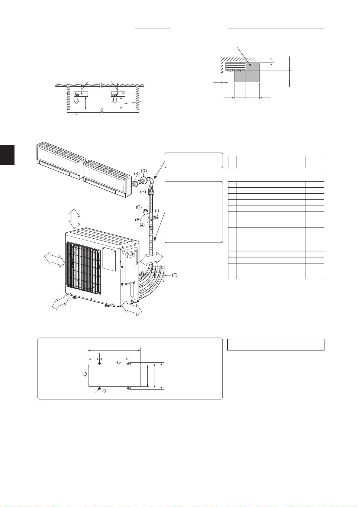
1-5. INSTALLATION DIAGRAM
ACCESSORIES
Checkthefollowingpartsbeforeinstallation.
(1) Drainsocket 1
(2) Draincap 2
PARTS TO BE PROVIDED AT YOUR SITE
(A) Powersupplycord* 1
(B)
Indoor/outdoorunitconnectingwire*
1
(C) Extensionpipe 1
(D) Wallholecover 1
(E) Pipingtape 1
(F)
Extensiondrainhose
(orsoftPVChose,15mminner
diameterorhardPVCpipeVP16)
1
(G) Refrigerationoil
Little
amount
(H) Putty 1
(I) Pipexingband 2to7
(J) Fixingscrewfor(I) 2to7
(K) Wallholesleeve 1
(L)
SoftPVChose,15mminner
diameterorhardPVCpipeVP16
fordrainsocket(1)
1
Note:
*Placeindoor/outdoorunitconnectingwire(B)and
powersupplycord(A)atleast1mawayfromthe
TVantennawire.
The“Q’ty”for(B)to(K)intheabovetableisquantity
tobeusedperindoorunit.
Unitsshouldbeinstalledbylicensedcontractor
accordingtolocalcoderequirements.
Outdoor unit installation
Airinlet
169 500
Airinlet
4-10×21Ovalholes
396
Airoutlet
840
(Unit:mm)
361
330
1-6. DRAIN PIPING FOR OUTDOOR UNIT
Pleaseperformthedrainpipingworkonlywhendrainingfromoneplace.
1)Chooseoneholetodischargedrainandinstallthedrainsocket(1)tothehole.
2)Closetherestoftheholeswiththedraincaps(2).
3)ConnectthesoftPVChose(L)of15mmintheinsidediameteronthemarketwiththedrainsocket(1)andleaddrain.
Note:
Installtheunithorizontally.
Donotusethedrainsocket(1)andthedraincaps(2)inthecoldregions.Drainmayfreezeanditmakesthefanstop.
Theoutdoorunitproducescondensateduringtheheatingoperation.Selecttheinstallationplacetoensuretopreventtheoutdoorunitand/orthegroundsfrom
beingwetbydrainwaterordamagedbyfrozendrainwater.
100ormore
500ormore
100ormore
Servicespace
350ormore
350ormore
6. Service space
Providespaceforserviceandmaintenanceasshowninthegure.
• Wheninstallingtheunitinanareathatisenclosedwithwallssuch
asaverandah,besuretohaveenoughspaceasshownbelow.
Inthiscase,theairconditioningcapacityandpowerconsumption
mightdeteriorate.
• Whenthereisalackofairoworthereisapossibilityofbecoming
shortcycle,installanoutletguideandmakesurethereisenough
spacebehindoftheunit.
• Wheninstallingtwoormoreunits,donotinstalltheunitsinfrontor
behindeachother.
5. Obstacles in front, behind and on side(s)
200ormore
100ormore
350ormore
500ormore
500ormore
Heightoftheobstacleis1200orless
(Unit:mm)
BN79A289H01_en.indd 3 2016/04/20 14:52:58
En-4
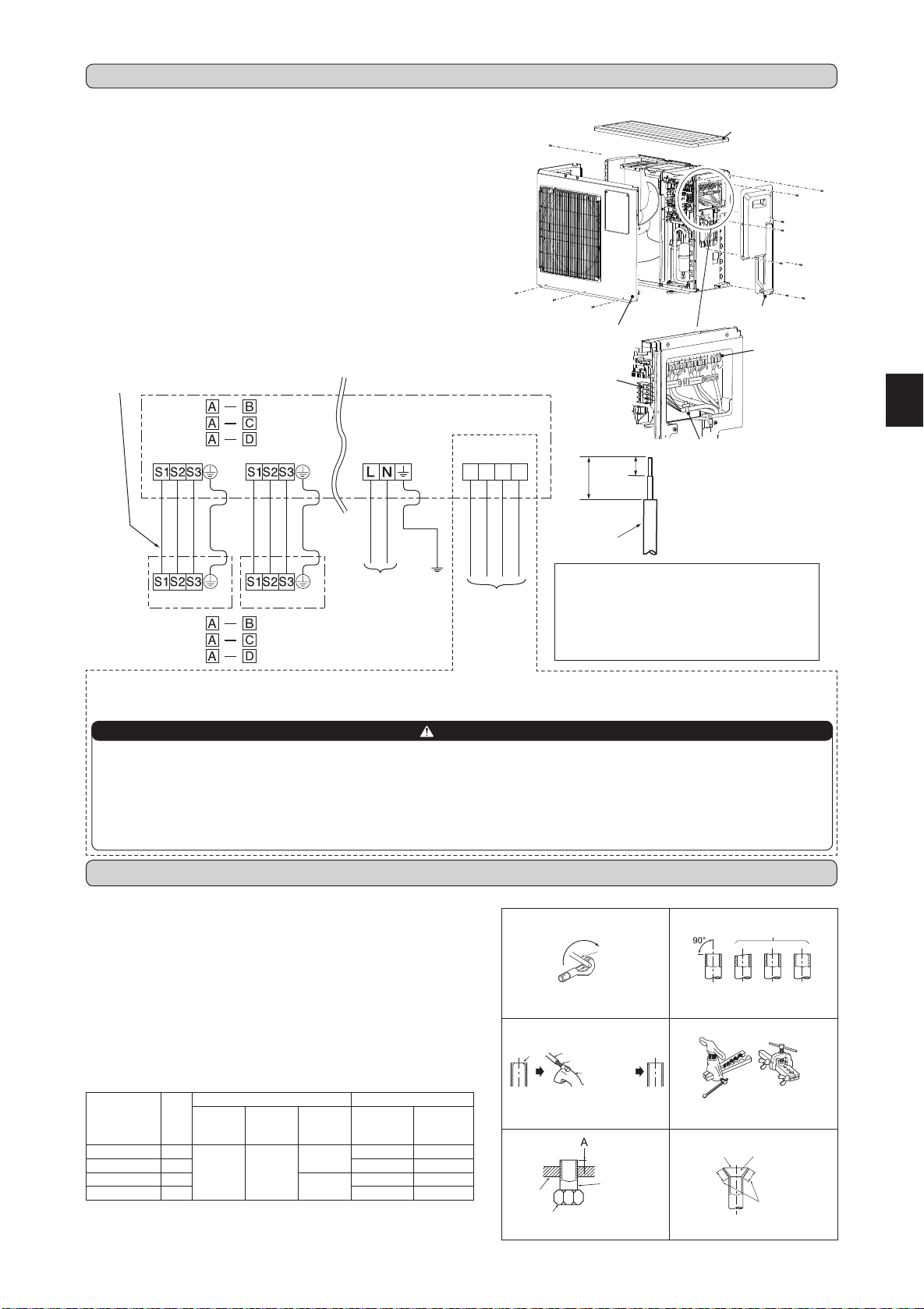
1 2 3 C
(MXZ-2E)
(MXZ-3E)
(MXZ-4E)
(MXZ-2E)
(MXZ-3E)
(MXZ-4E)
35mm
15mm
Leadwire
• Besuretoattacheachscrewtoitscorrespondent
terminalwhensecuringthecordand/orthewireto
theterminalblock.
• Makeearthwirealittlelongerthanothers.
(Morethan35mm)
• Forfutureservicing,giveextralengthtothecon-
nectingwires.
<OUTDOORUNIT>
Indoor/outdoorunit
connectingwire
<INDOORUNIT>
Terminalblock
Terminalblock Terminalblock
Terminalblockfor
powersupply
Terminalblock
2-1. CONNECTING WIRES FOR OUTDOOR UNIT
1)Removetheservicepanel,toppanel,frontpanel.
2)Loosenterminalscrew,andconnectindoor/outdoorunitconnectingwire(B)from
theindoorunitcorrectlyontheterminalblock.Becarefulnottomakemis-wiring.
Fixthewiretotheterminalblocksecurelysothatnopartofitscoreisappeared,
andnoexternalforceisconveyedtotheconnectingsectionoftheterminalblock.
3)Firmlytightentheterminalscrewstopreventthemfromloosening.Aftertightening,
pullthewireslightlytoconrmthattheydonotmove.
4)Perform2)and3)foreachindoorunit.
5)Connectpowersupplycord(A).
6)ConnectthedemandcontroltransmissioncabletotheterminalblockforDRED
Interface.
7)Fixindoor/outdoorunitconnectingwire(B)andpowersupplycord(A)withthe
cableclamps.
8)Fixthedemandcontroltransmissioncablewiththecablestrap.
9)Closetheservicepanel,toppanel,frontpanelsecurely.Makesurethat3-2.PIPE
CONNECTIONiscompleted.
•
Aftermakingconnectionsbetweenbothpowersupplycord(A)andindoor/outdoor
unitconnectingwire(B),besuretoxbothcableandwirewithcableclamps.
2. OUTDOOR UNIT INSTALLATION
POWERSUPPLY
~/N230V50Hz
ThisunithasdemandresponsecapabilitywhichiscompliantwithAS/NZS4755.3.1.Toactivatethisfunction,youneedtomakeacontractwithremote
agentssuchaselectricsupplycompany,thenthisunitshouldbeconnectedtoDemandresponseenablingdevise(DRED).Forfurtherinformation,
consultyourdealer.Thisunitsupports3DemandResponseModes(DRMs):DRM1,DRM2andDRM3.
CAUTION
•Topreventmalfunctioncausedbynoise,routethecordconnectingthisunittoDREDandthepowersupplycordasparallelaspossible.
•Donotconnectthedemandcontroltransmissioncabletotheterminalblockforpowersupply.
•Donotpull,extremelybendorapplystrongpressureonthewiretopreventfailure.
•DonotscrewDREDtooutdoorunit.
•DonotputDREDinoutdoorunit.
•Secureelectricalwiringaboveclamp.
•DonotgetDREDwirecaughtintheservicepanel.
1:DRM1
2:DRM2
3:DRM3
C:COMMON
AS/NZS4755
terminalblock
Fig.1 Fig.2
Fig.3 Fig.4
Fig.5 Fig.6
3-1. FLARING WORK
Pipediameter
(mm)
Nut
(mm)
A(mm) Tighteningtorque
Clutch
typetool
forR410A
Clutch
typetool
forR22
Wingnut
typetool
forR22
N•m kgf•cm
ø6.35(1/4”) 17
0to0.5 1.0to1.5
1.5to2.0
13.7to17.7 140to180
ø9.52(3/8”) 22 34.3to41.2 350to420
ø12.7(1/2”) 26
2.0to2.5
49.0to56.4 500to575
ø15.88(5/8”) 29 73.5to78.4 750to800
TiltedUnevenBurred
Good
Nogood
Burr
Copperpipe
Sparereamer
Pipecutter
Smoothall
around
Evenlength
allaround
Insideisshin-
ingwithoutany
scratches.
Flarenut
Die
Copperpipe
Clutchtype
Flaringtool
Wingnuttype
Copper
pipe
1)Cutthecopperpipecorrectlywithpipecutter.(Fig.1,2)
2)Completelyremoveallburrsfromthecutcrosssectionofpipe.(Fig.3)
• Aimthecopperpipedownwardwhileremovingburrstopreventburrsfrom
droppinginthepipe.
3)Removearenutsattachedtoindoorandoutdoorunits,thenputthemonpipe
havingcompletedburrremoval.(Notpossibletoputthemonafteraringwork.)
4)Flaringwork(Fig.4,5).Firmlyholdcopperpipeinthedimensionshowninthe
table.SelectAmmfromthetableaccordingtothetoolselected.
5)Check
• ComparethearedworkwithFig.6.
• Ifareisnotedtobedefective,cutoffthearedsectionanddoaringwork
again.
3. FLARING WORK AND PIPE CONNECTION
Terminalblock
forDREDInterface
Frontpanel
Servicepanel
Terminalblock
forpowersupply
Cablestrap
Thetipshouldbe
pointedupwards.
Toppanel
BN79A289H01_en.indd 4 2016/04/20 14:53:00
En-5
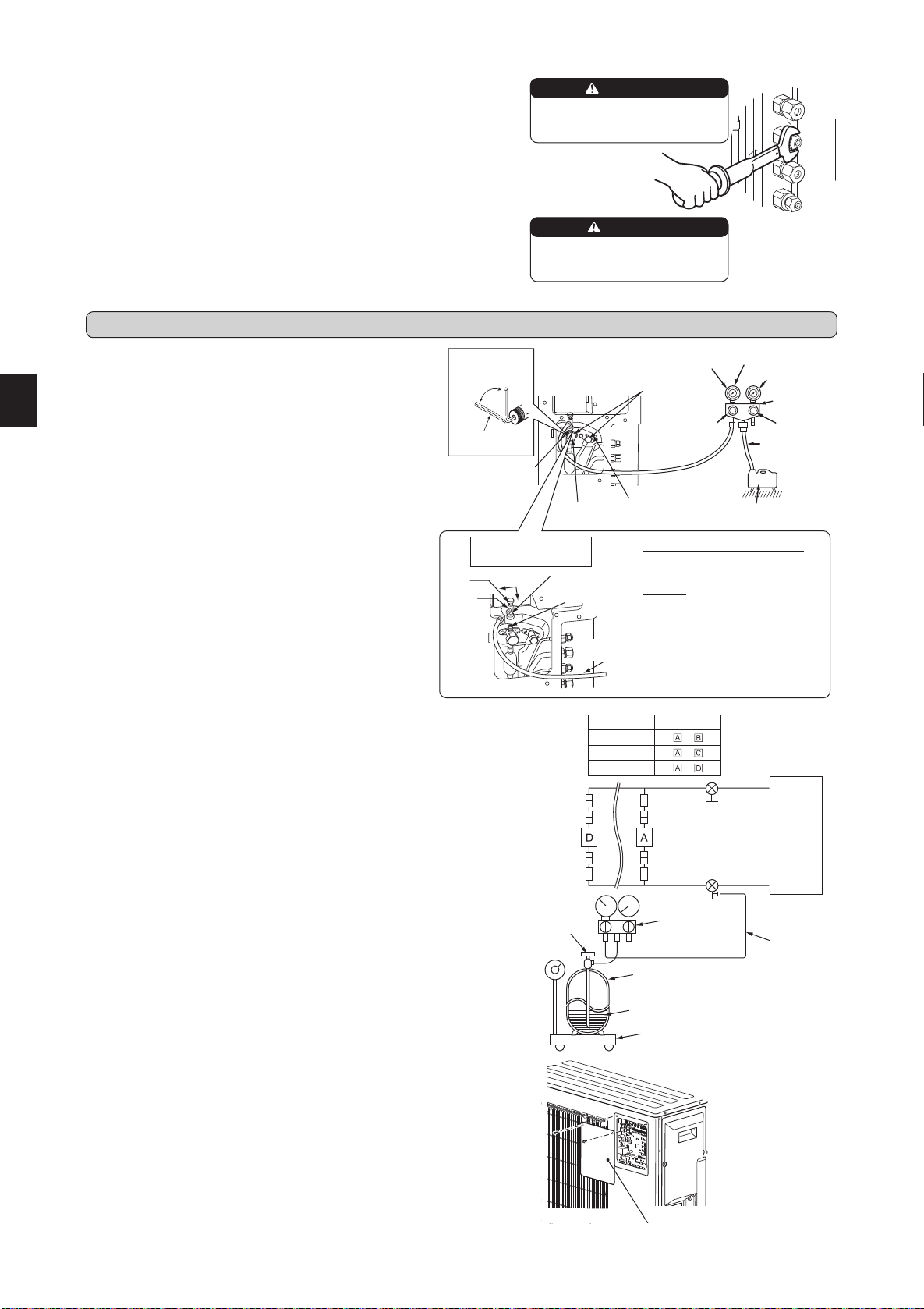
4-1. PURGING PROCEDURES AND LEAK TEST
4-2. GAS CHARGE
Performgaschargetounit.
1)Connectgascylindertotheserviceportofstopvalve.
2)Performairpurgeofthepipe(orhose)comingfromrefrigerantgascylinder.
3)Replenishspeciedamountoftherefrigerant,whileoperatingtheairconditioner
forcooling.
Note:
Incaseofaddingrefrigerant,complywiththequantityspeciedfortherefrigerat-
ingcycle.
CAUTION:
Whenchargingtherefrigerantsystemwithadditionalrefrigerant,besuretouseliquid
refrigerant.Addinggasrefrigerantmaychangethecompositionoftherefrigerantin
thesystemandaffectnormaloperationoftheairconditioner.Also,chargetheliquid
refrigerantslowly,otherwisethecompressorwillbelocked.
Tomaintainthehighpressureofthegascylinder,warmthegascylinderwithwarm
water(under40°C)duringcoldseason.Butneverusenakedreorsteam.
1)Removeserviceportcapofstopvalveonthesideoftheoutdoorunit
gaspipe.(Thestopvalvesarefullyclosedandcoveredincapsin
theirinitialstate.)
2)Connectgaugemanifoldvalveandvacuumpumptoserviceportof
stopvalveonthegaspipesideoftheoutdoorunit.
3)Runthevacuumpump.(Vacuumizeformorethan15minutes.)
4)Checkthevacuumwithgaugemanifoldvalve,thenclosegauge
manifoldvalve,andstopthevacuumpump.
5)Leaveasitisforoneortwominutes.Makesurethepointerofgauge
manifoldvalveremainsinthesameposition.Conrmthatpressure
gaugeshows-0.101MPa[Gauge](-760mmHg).
6)Removegaugemanifoldvalvequicklyfromserviceportofstopvalve.
7)
Fullyopenallstopvalvesonthegaspipeandtheliquidpipe.Operating
withoutfullyopeninglowerstheperformanceandthiscausestrouble.
8)Referto1-2.,andchargetheprescribedamountofrefrigerantif
needed.Besuretochargeslowlywithliquidrefrigerant.Otherwise,
compositionoftherefrigerantinthesystemmaybechangedand
affectperformanceoftheairconditioner.
9)Tightencapofserviceporttoobtaintheinitialstatus.
10
)Leaktest
Union
Stop valve
Liquid
pipe
Indoor
unit
Stop valve with
service port
Gas
pipe
Outdoor
unit
Union
Union
Union
Model Indoor unit
MXZ-2E
–
MXZ-3E
–
MXZ-4E
–
Refrigerantgas
cylinder
operatingvalve
(forR410A)
Gaugemanifold
valve(forR410A)
Chargehose
(forR410A)
RefrigerantgascylinderforR410Awithsiphon
Electronicscaleforrefrigerantcharging
Refrigerant(liquid)
Stopvalve
forGAS
Stopvalvecap
(Torque19.6to
29.4N•m,200
to300kgf•cm)
Gaugemanifold
valve(forR410A)
Compoundpressure
gauge(forR410A)
–0.101MPa
(–760mmHg)
Handle
Low
HandleHigh
Vacuumpump
(forR410A)
*Close
*Open
Hexagonalwrench
*4to5turns
Stopvalve
forLIQUID
Pressuregauge
(forR410A)
Precautionswhenus-
ingthecontrolvalve
Whenattachingthecontrolvalve
totheserviceport,valvecoremay
deformorloosenifexcesspres-
sureisapplied.Thismaycause
gasleak.
Serviceport
Chargehose
(forR410A)
Body
Close
Open
Control
valve
A
Whenattachingthecontrolvalveto
theserviceport,makesurethatthe
valvecoreisinclosedposition,and
then tighten part A. Do not tighten
partA orturnthe bodywhen valve
coreisinopenposition.
Serviceportcap
(Torque13.7to
17.7N•m,140to
180kgf•cm)
Chargehose
(forR410A)
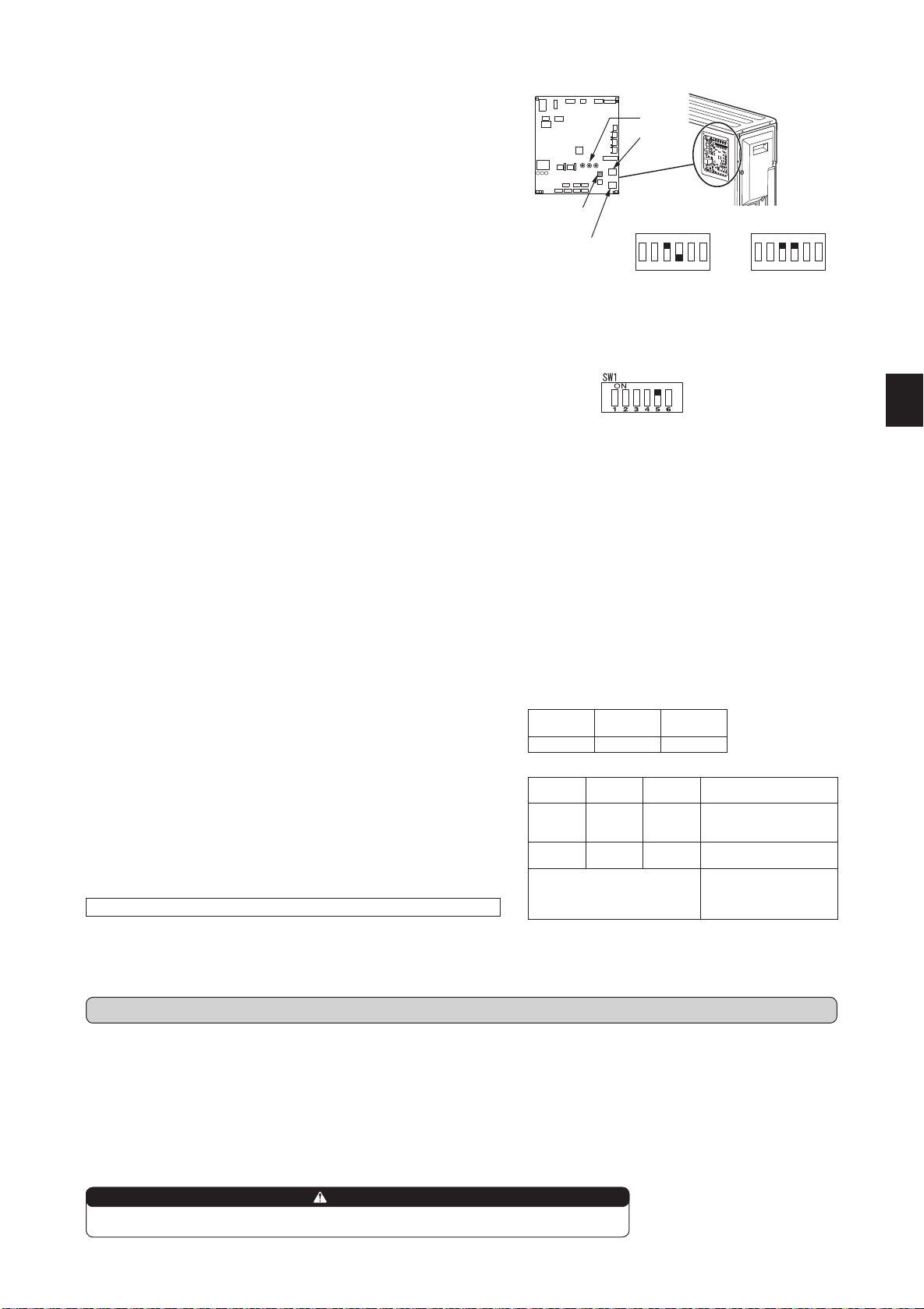
4-3. REMOVING THE MAINTENANCE PANEL
ThesettingofDipSwitchontheoutdoorcontrollerboardcanbechangedwithout
removingthefrontpanel.
FollowtheproceduresbelowtoremovethemaintenancepanelandsettheDip
Switch.
1)Removescrew(s)whichxthemaintenancepanel.
2)Removethemaintenancepanel,andperformnecessarysettings.
3)Installthemaintenancepanel.
Note:
Makesuretoxthemaintenancepanelsecurely.Incompleteinstallationcould
causemalfunction.
Maintenancepanel
4. PURGING PROCEDURES, LEAK TEST, AND TEST RUN
3-2. PIPE CONNECTION
1)Applyathincoatofrefrigerationoil(G)tothearedendsofthepipesandthepipecon-
nectionsoftheoutdoorunit.Donotapplyrefrigerationoilonscrewthreads.Excessive
tighteningtorquewillresultindamageonthescrew.
2)Alignthecenterofthepipewiththatofthepipeconnectionsoftheoutdoorunit,thenhand
tightenthearenut3to4turns.
3)Tightenthearenutwithatorquewrenchasspeciedinthetable.
•Over-tighteningmaycausedamagetothearenut,resultinginrefrigerantleakage.
•Besuretowrapinsulationaroundthepiping.Directcontactwiththebarepipingmay
resultinburnsorfrostbite.
3-3. INSULATION AND TAPING
1)Coverpipingjointswithpipecover.
2)Foroutdoorunitside,surelyinsulateeverypipingincludingvalves.
3)Usingpipingtape(E),applytapingstartingfromtheentryofoutdoorunit.
• Stoptheendofpipingtape(E)withtape(withadhesiveagentattached).
•
Whenpipinghavetobearrangedthroughaboveceiling,closetorwherethetemperature
andhumidityarehigh,windadditionalcommerciallysoldinsulationtopreventcondensation.
When installing the unit, securely
connect the refrigerant pipes before
starting the compressor.
When there are the ports which are
not used, make sure their nuts are
tightened securely.
WARNING
CAUTION
BN79A289H01_en.indd 5 2016/04/20 14:53:01
En-6
4-4. LOCKING THE OPERATION MODE OF THE AIR CONDITIONER (COOL, DRY, HEAT)
4-5. LOWERING THE OPERATION NOISE OF THE OUTDOOR UNIT
• Descriptionofthefunction:
Withthisfunction,oncetheoperationmodeislockedtoeitherCOOL/DRYmode
orHEATmode,theairconditioneroperatesinthatmodeonly.
* Changingthesettingisrequiredtoactivatethisfunction.Pleaseexplainabout
thisfunctiontoyourcustomersandaskthemwhethertheywanttouseit.
[How to lock the operation mode]
1)Besure toturn offthe mainpower forthe airconditioner beforemaking the
setting.
2)Setthe“3”ofSW1ontheoutdoorcontrollerboardtoONtoenablethisfunction.
3)Tolockthe operationmodeinCOOL/DRYmode,setthe “4”ofSW1onthe
outdoorcontrollerboardtoOFF.TolocktheoperationinHEATmode,setthe
sameswitchtoON.
4)Turnonthemainpowerfortheairconditioner.
• Descriptionofthefunction:
Withthisfunction,theoperatingnoiseoftheoutdoorunitcanbeloweredbyreducingtheoperationload,forexample,duringnighttimeinCOOLmode.
However,pleasenotethatthecoolingandheatingcapacitymaylowerifthisfunctionisactivated.
* Changingthesettingisrequiredtoactivatethisfunction.Pleaseexplainaboutthisfunctiontoyourcustomersandaskthemwhethertheywanttouseit.
Lowertheoperatingnoise
[How to lower the operating noise]
1)Besuretoturnoffthemainpowerfortheairconditionerbeforemakingthesetting.
2)Setthe“5”ofSW1ontheoutdoorcontrollerboardtoONtoenablethisfunction.
3)Turnonthemainpowerfortheairconditioner.
4-6. TEST RUN
• Testrunsoftheindoorunitsshouldbeperformedindividually.Seetheinstallationmanualcomingwiththeindoorunit,andmakesurealltheunitsoperate
properly.
• Ifthetestrunwithalltheunitsisperformedatonce,possibleerroneousconnectionsoftherefrigerantpipesandtheindoor/outdoorunitconnectingwires
cannotbedetected.Thus,besuretoperformthetestrunonebyone.
About the restart protective mechanism
Oncethecompressorstops,therestartpreventivedeviceoperatessothecompressorwillnotoperatefor3minutestoprotecttheairconditioner.
Wiring/piping correction function
Thisunithasawiring/pipingcorrectionfunctionwhichcorrectswiringandpipingcombination.Whenthereispossibilityofincorrectwiringandpipingcombi-
nation,andconrmingthecombinationisdifcult,usethisfunctiontodetectandcorrectthecombinationbyfollowingtheproceduresbelow.
Makesurethatthefollowingisdone.
• Powerissuppliedtotheunit.
• Stopvalvesareopen.
Note:
Duringdetection,theoperationoftheindoorunitiscontrolledbytheoutdoorunit.Duringdetection,theindoorunitautomaticallystopsoperation.Thisisnot
amalfunction.
Whenrelocatingordisposingoftheairconditioner,pumpdownthesystemfollowingtheprocedurebelowsothatnorefrigerantisreleasedintotheatmosphere.
1)Turnoffthebreaker.
2)Connectthegaugemanifoldvalvetotheserviceportofthestopvalveonthegaspipesideoftheoutdoorunit.
3)Fullyclosethestopvalveontheliquidpipesideoftheoutdoorunit.
4)Turnonthebreaker.
5)StarttheemergencyCOOLoperationonalltheindoorunits.
6)Whenthepressuregaugeshows0.05to0MPa[Gauge](approx.0.5to0kgf/cm
2
),fullyclosethestopvalveonthegaspipesideoftheoutdoorunitand
stoptheoperation.(Refertotheindoorunitinstallationmanualaboutthemethodforstoppingtheoperation.)
*Iftoomuchrefrigeranthasbeenaddedtotheairconditionersystem,thepressuremaynotdropto0.05MPa[Gauge](approx.0.5kgf/cm
2
),ortheprotection
functionmayoperateduetothepressureincreaseinthehigh-pressurerefrigerantcircuit.Ifthisoccurs,usearefrigerantcollectingdevicetocollectallof
therefrigerantinthesystem,andthenrechargethesystemwiththecorrectamountofrefrigerantaftertheindoorandoutdoorunitshavebeenrelocated.
7)Turnoffthebreaker.Removethepressuregaugeandtherefrigerantpiping.
4-7. EXPLANATION TO THE USER
• UsingtheOPERATINGINSTRUCTIONS,explaintotheuserhowtousetheairconditioner(howtousetheremotecontroller,howtoremovetheairlters,
howtoremoveorputtheremotecontrollerintheremotecontrollerholder,howtoclean,precautionsforoperation,etc.).
• RecommendtheusertoreadtheOPERATINGINSTRUCTIONScarefully.
Procedure
Pressthepiping/wiringcorrectionswitch(SW871)1minuteormoreafterturningonthe
powersupply.
• Correctioncompletesin10to15minutes.Whenthecorrectioniscompleted,itsresult
isshownbyLEDindication.Detailsaredescribedinthefollowingtable.
• Tocancelthisfunctionduringitsoperation,pressthepiping/wiringcorrectionswitch
(SW871)again.
• Whenthecorrectioncompletedwithouterror,donotpressthepiping/wiringcorrection
switch(SW871)again.
Whentheresultis“Notcompleted”,pressthepiping/wiringcorrectionswitch(SW871)again
tocancelthisfunction.Then,conrmthewiringandpipingcombinationinaconventional
mannerbyoperatingtheindoorunitsonebyone.
• Theoperationisdonewhilethepowerissupplied.Makesurenottocontactpartsother
thantheswitch,includingtheP.C.board.Thismaycauseelectricshockorburnbyhot
partsandlivepartsaroundtheswitch.ContactingthelivepartsmaycauseP.C.board
damage.
• TopreventelectroniccontrolP.C.boarddamage,makesuretoperformstaticelimination
beforeoperatingthisfunction.
• Thisfunctiondoesnotoperatewhentheoutsidetemperatureis0°Corbelow.
LED indication during detection:
LED1
(Red)
LED2
(Yellow)
LED3
(Green)
Lighted Lighted Once
Result of piping/wiring correction function
LED1
(Red)
LED2
(Yellow)
LED3
(Green)
Result
Lighted Notlighted Lighted
Completed
(Problemcorrectedor
normal)
Once Once Once
Notcompleted
(Detectionfailed)
Otherindications
Referto“SAFETYPRE-
CAUTIONSWHENLED
BLINKS”locatedbehind
thetoppanel.
When pumping down the refrigerant, stop the compressor before disconnecting the refrigerant pipes.
The compressor may burst and cause injury if any foreign substance, such as air, enters the pipes.
WARNING
5. PUMPING DOWN
HEAT
COOL/DRY
LED
SW1
SW871
SW2
SW1
ON
1 2 3 4 5 6
SW1
ON
1 2 3 4 5 6
BN79A289H01_en.indd 6 2016/04/20 14:53:02

BN79A289H01
HEAD OFFICE: TOKYO BUILDING, 2-7-3, MARUNOUCHI, CHIYODA-KU, TOKYO 100-8310, JAPAN
BN79A289H01_cover.indd 2 2016/04/07 16:27:46