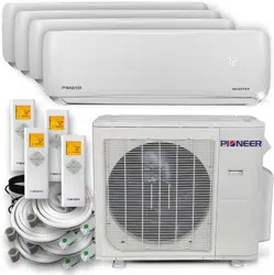

MULTI SPLIT SYSTEM OUTDOOR UNITS
SERVICE MANUAL
Multi zone
Two, Three, Four and Five Zones
DC INVERTER MULTI ZONE OUTDOOR UNITS
RevisionA:ODMI‐E‐1601‐PDB55/2016
ModelNumbers:
YN020GMFI22M2D Dual(2Zones)
YN030GMFI22M3D Triple(3Zones)
YN040GMFI22M4D Quad(4Zones)
YN050GMFI22M5D Quint(5Zones)
WARNING
Installation MUST conform with local building codes or, in the absence of local codes, with the National Electrical
Code NFPA70/ANSI C1-1993 or current edition and Canadian Electrical Code Part1 CSA C.22.1.
The information contained in the manual is intended for use by a qualified service technician familiar with safety
procedures and equipped with the proper tools and test instruments
Installation or repairs made by unqualified persons can result in hazards to you and others as well as irreversible
equipment damage.
Failure to carefully read and follow all instructions in this manual can result in equipment malfunction, property
damage, personal injury and/or death.
COPYRIGHT 2016, Parker Davis HVAC International Inc. All rights reserved. This document cannot be wholly or
partially copied, published or distributed without the written authorization from Parker Davis HVAC International, Inc.
Table of Contents
1. Indoor Unit Combination Table
2. Suggested Indoor Unit Model Numbers
3. Dimension Of Outdoor Unit
4. Refrigerant Cycle Diagram
5. Installation Details
6. Electronic Function
7. Wiring Diagrams
8. Trouble Shooting
9. Disassembly Instructions (Coming Soon)

CONTENTS
1. IndoorUnitCombination..........................................................................................................................................3
2. DimensionOfOutdoorUnit......................................................................................................................................4
3. RefrigerantCycleDiagram........................................................................................................................................5
4. InstallationDetails....................................................................................................................................................7
5.1Wrenchtorquesheetforinstallation.................................................................................................................7
5.2Connectingthecables........................................................................................................................................7
5.3Pipelengthandtheelevation.............................................................................................................................7
5.4Installationforthefirsttime..............................................................................................................................8
5.5Addingtherefrigerantafterrunningthesystemformanyyears....................................................................12
5.6Procedurewhenservicingtheindoorunitrefrigerationcircuit.......................................................................14
5.7Evacuationafterservicingtheoutdoorunitrefrigerationcircuit....................................................................14
6. ElectronicFunction.................................................................................................................................................15
6.1Abbreviation.....................................................................................................................................................15
6.2Electriccontrolworkingenvironment..............................................................................................................15
6.3MainProtection................................................................................................................................................15
6.4ControlandFunctions......................................................................................................................................17
7. WiringDiagrams.....................................................................................................................................................20
8. Troubleshooting.....................................................................................................................................................24
8.1Safety.................................................................................................................................................................24
8.2IndoorUnitErrorDisplay...................................................................................................................................25
8.3OutdoorUnitDisplay........................................................................................................................................30
8.4DiagnosisandSolution.....................................................................................................................................33
8.5TroubleCriterionOfMainParts.......................................................................................................................74
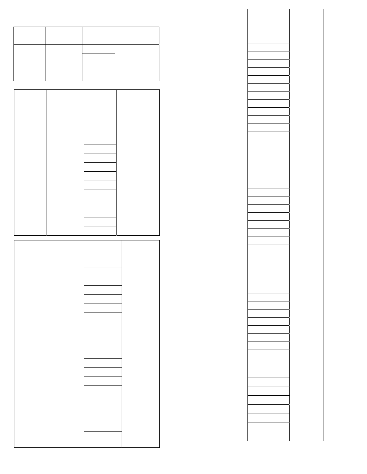
1. Indoor Unit Combination
Multi DC
Outdoor Unit
Min~Max
(Nominal)
Capacity
Suggested
Combination
Limit
TWO Zone
12,000~24,000
(18,000)
BTU/h
12
None
9+9
9+12
12+12
Multi DC
Outdoor Unit
Min~Max
(Nominal)
Capacity
Suggested
Combination
Limit
FIVE Zone
36,000~64,000
(48,000)
BTU/h
18+18
None
18+24
24+24
9+9+18
9+9+24
9+12+12
9+12+18
9+12+24
9+18+18
9+18+24
9+24+24
12+12+12
12+12+18
12+12+24
12+18+18
12+18+24
12+24+24
18+18+18
18+18+24
9+9+9+9
9+9+9+12
9+9+9+18
9+9+9+24
9+9+12+12
9+9+12+18
9+9+12+24
9+9+18+18
9+9+18+24
9+12+12+12
9+12+12+18
9+12+12+24
9+12+18+18
9+18+18+18
12+12+12+12
12+12+12+18
12+12+12+24
12+12+18+18
9+9+9+9+9
9+9+9+9+12
9+9+9+9+18
9+9+9+9+24
9+9+9+12+12
9+9+9+12+18
9+9+9+18+18
9+9+12+12+12
9+9+12+12+18
9+12+12+12+12
9+12+12+12+18
12+12+12+12+12
Multi DC
Outdoor Unit
Min~Max
(Nominal)
Capacity
Suggested
Combination
Limit
THREE
Zone
18,000~36,000
(27,000) BTU/h
Suggested
Combination
Maximum 1 piece
DUCTED or
FLEXMOUNT
Indoor unit
9+9
9+12
9+18
12+12
12+18
18+18
9+9+9
9+9+12
9+9+18
9+12+12
9+12+18
12+12+12
Multi DC
Outdoor Unit
Min~Max
(Nominal)
Capacity
Suggested
Combination
Limit
FOUR Zone
24,000~48,000
(36,000)
BTU/h
9+18
None
12+12
12+18
18+18
9+9+9
9+9+12
9+9+18
9+12+12
9+12+18
9+18+18
12+12+12
12+12+18
12+18+18
9+9+9+9
9+9+9+12
9+9+9+18
9+9+12+12
9+9+12+18
9+12+12+12
12+12+12+12
2. Dimension of the Outdoor Units
Model
Unit:
W D H W1 A B
YN020GMFI22M2D
mm
845 363 702 923 540 350
inch
33.3 14.3 27.6 36.0 21.3 13.8
YN030GMFI22M3D
mm
946 410 810 1034 673 403
inch
37.2 16.5 31.9 40.6 26.5 15.9
YN040GMFI22M4D
mm
946 410 810 1034 673 403
inch
37.2 16.5 31.9 40.6 26.5 15.9
YN050GMFI22M5D
mm
952 415 1333 1045 634 404
inch
37.5 16.3 52.5 41.1 25.0 15.9
Note: 5 circuit model will have 2 fans.
A
B
D
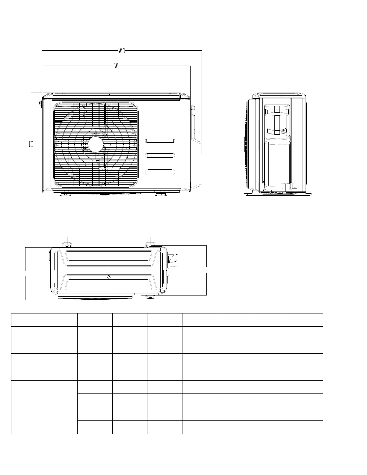
3. Refrigerant Cycle Diagram
4.1 Refrigeration circuit drawing of inverter DUAL (2 Zone)
LIQUID VALVE A
GAS VALVE A
HEAT
EXCHANGE
(EVAPORATOR)
HEAT
EXCHANGE
(CONDENSER)
Compressor
4-WAY VALVE
COOLING
HEATING
T2 Evaporator
temp. sensor
middle
T1 Room
temp. sensor
T3
Condenser
temp. sensor
T5 Discharge
temp. sensor
T4 Ambient
temp. sensor
INDOOR OUTDOOR
EXV A
CAPILIARY A
CHECK VALVE
CAPILIARY TUBE
EXV B
CAPILIARY B
LIQUID VALVE B
GAS VALVE B
Accumulator
T2B-A Evaporator
temp. sensor outlet
T2B-B
4.2 Refrigeration circuit drawing of inverter TRIPLE (3 Zone)
LIQUID VALVE A
GAS VALVE A
HEAT
EXCHANGE
(EVAPORATOR)
HEAT
EXCHANGE
(CONDENSER)
Compressor
4-WAY VALVE
COOLING
HEATING
T2 Evaporator
temp. sensor
middle
T1 Room
temp. sensor
T3
Condenser
temp. sensor
T5 Discharge
temp. sensor
T4 Ambient
temp. sensor
INDOOR OUTDOOR
EXV A
CAPILIARY A
CHECK VALVE
CAPILIARY TUBE
EXV B
CAPILIARY B
LIQUID VALVE B
GAS VALVE B
EXV C
CAPILIARY C
LIQUID VALVE C
GAS VALVE C
Accumulator
T2B-A Evaporator
temp. sensor outlet
T2B-B
T2B-C
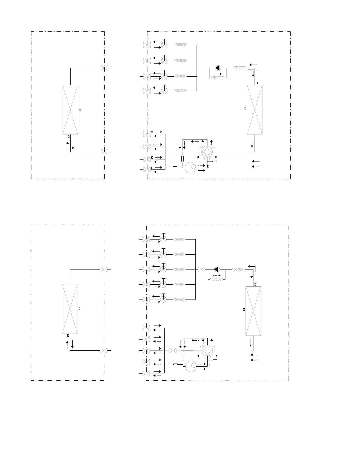
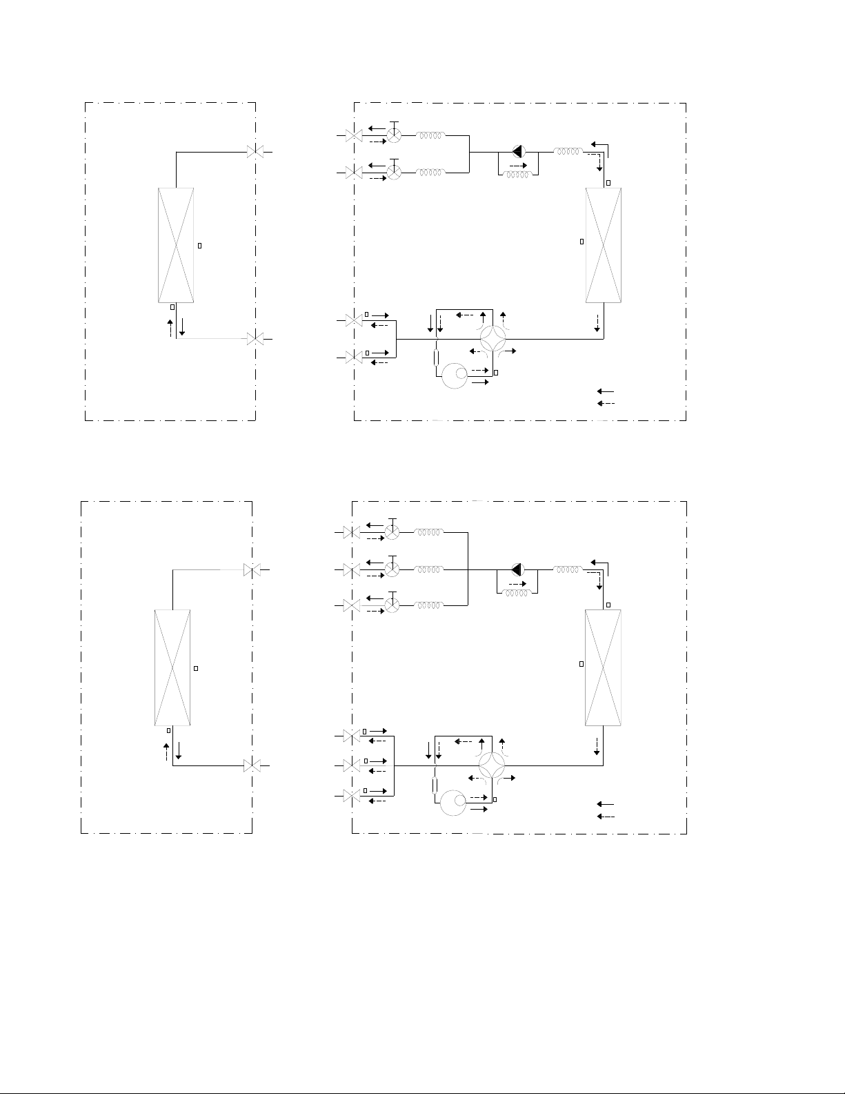
4.3 Refrigeration circuit drawing of inverter Quad(4Zone)
LIQUID VALVE A
GAS VALVE A
HEAT
EXCHANGE
(EVAPORATOR)
HEAT
EXCHANGE
(CONDENSER)
Compressor
4-WAY VALVE
COOLING
HEATING
T2 Evaporator
temp. sensor
middle
T1 Room
temp. sensor
T3
Condenser
temp. sensor
T5 Discharge
temp. sensor
T4 Ambient
temp. sensor
INDOOR OUTDOOR
EXV A
CAPILIARY A
CHECK VALVE
CAPILIARY TUBE
EXV B
CAPILIARY B
LIQUID VALVE B
GAS VALVE B
EXV C
CAPILIARY C
LIQUID VALVE C
GAS VALVE C
EXV D
CAPILIARY D
LIQUID VALVE D
GAS VALVE D
Accumulator
High pressure
switch
Low pressure
switch
T2B-A Evaporator
temp. sensor outlet
T2B-B
T2B-C
T2B-D
4.4RefrigerationcircuitdrawingofinverterQuint(5Zone)
LIQUID VALVE A
GAS VALVE A
HEAT
EXCHANGE
(EVAPORATOR)
HEAT
EXCHANGE
(CONDENSER)
COOLING
HEATING
T2 Evaporator
temp. sensor
T1 Room
temp. sensor
T3
Condenser
temp. sensor
T4 Ambient
temp. sensor
INDOOR OUTDOOR
EXV A
CAPILIARY A
CHECK VALVE
CAPILIARY TUBE
EXV B
CAPILIARY B
LIQUID VALVE B
GAS VALVE B
EXV C
CAPILIARY C
LIQUID VALVE C
GAS VALVE C
EXV D CAPILIARY D
LIQUID VALVE D
GAS VALVE D
EXV E
CAPILIARY E
LIQUID VALVE E
GAS VALVE E
Compressor
4-WAY VALVE
T5 Discharge
temp. sensor
Accumulator
High pressure
switch
Low pressure
switch
4. Installation Details
5.1 Wrench torque sheet for installation
Outside
diameter
Torque
Additional tightening
torque
mm inch N.cm N.cm
Ф6.35 1/4 1500 (11 LbF*Ft) 1600 (12 LbF*Ft)
Ф9.52 3/8 2500 (18 LbF*Ft) 2600 (19LbF*Ft)
Ф12.7 1/2 3500 (26 LbF*Ft) 3600 (27 LbF*Ft)
5.2 Connecting the cables
The main power input connection wire size
should be selected according to the following
table.
Unit AWG
DUAL (2 Zone) 14
TRIPLE (3 Zone) 14
QUAD (4 Zone) 12
QUINT (5 Zone) 10
For the cable set connecting indoor units to the
outdoor unit, use 16AWG (for all indoor types).
5.3 Pipe length and the elevation
Maximum piping length and height difference
2 Zone 3 Zone 4 Zone 5 Zone
Max. length for all
rooms (m)
30
(100ft)
45
(150ft)
60
(200ft)
75
(250ft)
Max. length to one
Indoor Unit (m)
20 (65ft) 25 (80ft)
30
(100ft)
30
(100ft)
Max.
height
difference
between
Indoor /
Outdoor
(m)
ODU
higher
than
IDU
10 (33ft) 10 (33ft)
10
(33ft)
10 (33ft)
ODU
lower
than
IDU
15 (50ft) 15 (50ft)
15
(50ft)
15 (50ft)
Max. height
difference between
Indoor Units (m)
10 (33ft) 10 (33ft)
10
(33ft)
10 (33ft)
Additional refrigerant charge
2 Zone 3 Zone 4 Zone 5 Zone
Pre-charged up to
max total pipe
length m (ft)
15
(50 ft)
22.5
(75 ft)
30
(100 ft)
37.5
(125 ft)
Additional
refrigerant
charge
needed
beyond
total max
length
g
15 g per
excess
meter
beyond
total 15
meters
15 g per
excess
meter
beyond
total 23
meters
15 g per
additiona
l feet
beyond
total 30
feet
15 g per
additional
feet
beyond
total 38
feet
oz
0.16 oz
per
excess
foot
beyond
total 50
feet
0.16 oz
per
excess
foot
beyond
total 75
feet
0.16 oz
per
excess
foot
beyond
total 100
feet
0.16 oz
per
excess
foot
beyond
total 125
feet
Caution:
● Refrigerant pipe diameters change according to
indoor unit model to be connected. When
extending the pipes, refer to the tables below.
● When refrigerant pipe diameter is different from
that of the outdoor unit connectors, additional
adapter(s) would be required and will be factory
supplied with your unit.
Indoor unit
Extension pipe diameter
(mm/inch)
Model
Pipe diameter
(mm/inch)
9K
Liquid 6.35 (1/4) Liquid 6.35 (1/4)
Gas 9.52 (3/8) Gas 9.52 (3/8)
12K 18K
Liquid 6.35 (1/4) Liquid 6.35 (1/4)
Gas 12.7 (1/2) Gas 12.7 (1/2)
24K
Liquid 9.52 (3/8) Liquid 9.52 (3/8)
Gas 15.9 (5/8) Gas 15.9 (5/8)
Outdoor unit union diameter (mm/inch)
Dual(2Zone)
Liquid
6.35 (1/4)
*2
Gas
9.52 (3/8)
*2
Triple(3Zone)
Liquid
6.35 (1/4)*3
Gas
9.52 (3/8)
*3
Quad(4Zone)
Liquid
6.35 (1/4)*4
Gas
9.52 (3/8)
*3
12.7 (1/2) *1
Quint(5Zone)
Liquid
6.35 (1/4)*5
Gas
9.52 (3/8)
*3
12.7 (1/2) *2
5.4 Installation for the first time:
Air and moisture in the refrigerant system will result
in significant problems with your system:
● Pressure in the system rises.
● Operating current rises.
● Cooling or heating efficiency drops.
● Moisture in the refrigerant circuit may freeze and
block flow through the expansion devices.
● Water when mixed with the refrigerant and oil will
create acid that will damage the motor windings
and components of the compressor.
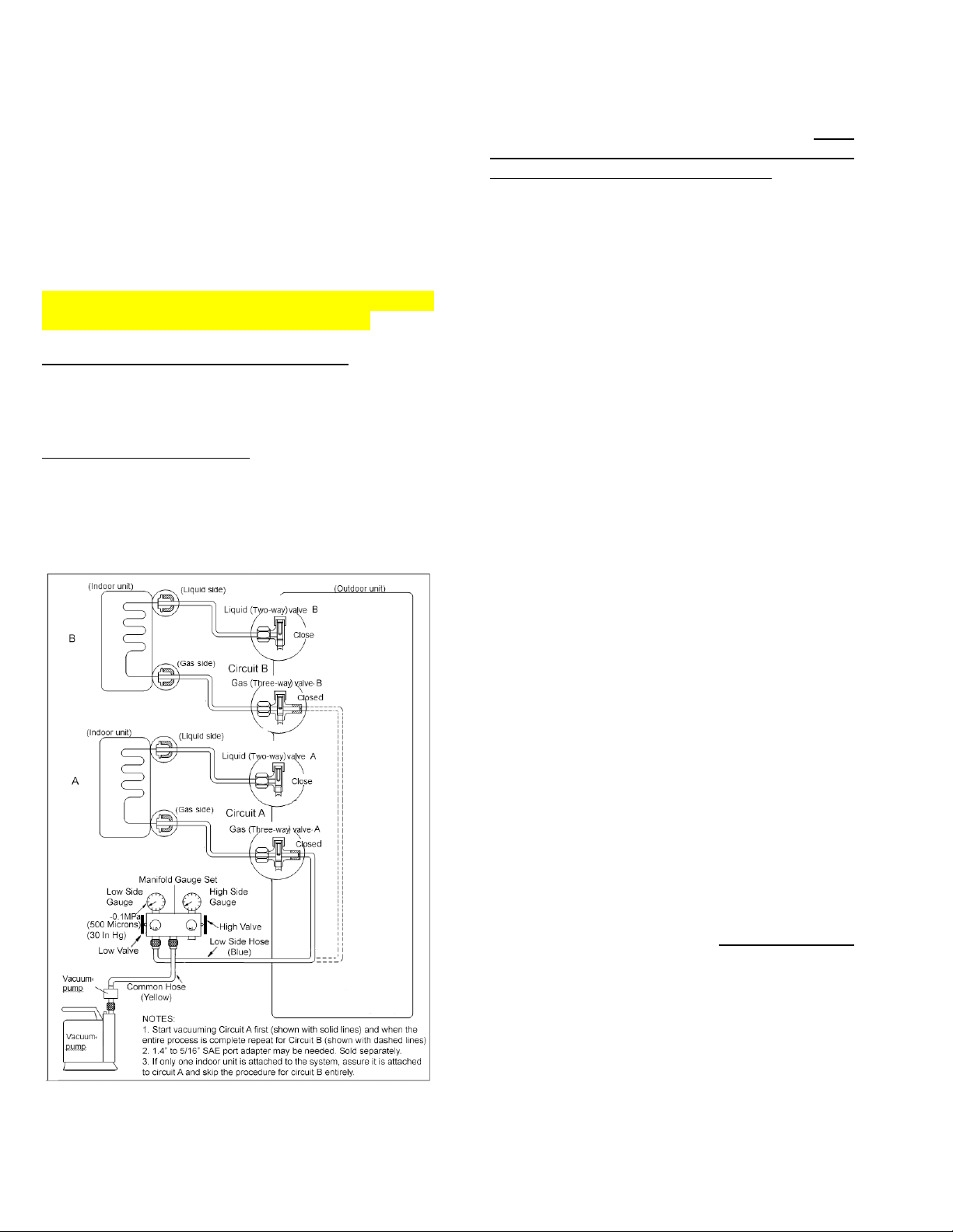
PROCEDURE FOR DUAL (2) ZONE OUTDOOR
UNITS ARE DIFFERENT FROM OTHERS.
5.4.1. FOR DUAL (2 ZONE SYSTEMS):
Indoor units and the pipes between indoor and
outdoor units must be evacuated and leak tested to
remove trapped air and moisture from the system.
ONE CIRCUIT AT A TIME. This procedure should
start after all electrical connections are finalized and
the system receives proper power for immediate test
running, to be performed one circuit at a time.
Evacuation using a vacuum pump:
1. Completely tighten ALL brass flare nuts, which
connect the ends of copper refrigerant lines to
the attached indoor units and the circuit service
valves on the outdoor unit, using proper torque.
2. Assure that both the 2-way (Liquid) and 3-way
(Gas) valves for each circuit at the outdoor unit
STAY CLOSED as they arrived originally.
3. Connect the low pressure hose on your gauge
manifold (usually blue) to the 3-way (Gas)
valve’s service port, belonging to circuit A. Note:
If there is only one indoor unit it should be
connected to circuit A as the primary.
4. If the manifold gauge set’s hoses have 1/4” SAE
connections, a 1/4” to 5/16” SAE port adapter will
be needed. (Sold separately).
5. Connect the center hose of the gauge manifold
(usually yellow) to the vacuum pump.
6. Fully open the Low side valve on the low
pressure side of your gauge manifold. Assure
that the High side valve on the high pressure
side of your gauge manifold stays closed.
7. Start the vacuum pump and operate according to
pump manufacturer’s specifications. If your
vacuum pump has a valve, open it as well.
8. Perform vacuuming / evacuation for a minimum
period of 30 minutes and check that the low
pressure gauge indicates a vacuum of 30 in/hg
(500 microns). (A more sensitive vacuum gauge
should be used if available).
9. If the proper vacuum cannot be achieved within
30 minutes, the vacuum pump should be kept
running for an additional 15 minutes. If after the
additional 15 minutes of operation, the vacuum
still cannot be achieved, there could be a leak at
one or more of the flare pipe connections at
either end of a refrigerant pipes. Leak must be
located and the leaking nut must be tightened
properly before re-vacuuming the circuit.
10.
If the vacuum is achieved, close the low side
valve at the low pressure side on your gauge
manifold first and shut the vacuum pump off.
Leave the gauge manifold set and the hoses
connected and recheck the vacuum reading 15
minutes later to assure there is no vacuum loss.
(Very small increase in vacuum level is normal).
11. Circuit A is now dry and free of contaminants. Do
not remove the hose of your gauge manifold set
from the service port.
12. Remove the 2-way (Liquid) Valve’s brass dust
cap of circuit A. Insert proper size Allen wrench
into the valve core and turn it counter clockwise
for 1 turn for, wait for 3 seconds and quickly close
the valve by turning it in reverse direction. Check
your low pressure gauge on the manifold to
assure it now indicates positive pressure of
approximately 80 to 120 PSI in your lines.
13. Apply soap-water mixture on both the indoor unit
connections and the outdoor unit connections for
circuit A with a soft brush to check for leakage at
the connecting points of the piping. If you notice
air bubbles, the specific connector has leakage
and must be tightened to stop the leakage.
(An electronic leak detector will be more efficient
to use for this if available).
14. Re-insert proper size Allen wrench into the valve
core of the Liquid Valve (2 way) valve for circuit
A and turn it counter clockwise until it is fully back
seated. Do not force it, once it stops turning.
Repeat the leak checking procedure entirely at
all connections of circuit A. If you find a new leak,
close the 2-way (Liquid) valve you just opened
first and tighten the flare nut at the leaking
connection until the leak is sealed. Reopen the
2-way (Liquid) valve and check again.
15. Remove the 3-way (Gas) Valve’s dust cap for
circuit A. Insert proper size Allen wrench into the
valve core and turn it counter clockwise until it is
fully back seated. Do not force it, once it stops
turning.
16. Power up the system, and run the indoor unit for
circuit A in COOLING mode to assure that all
functions are working.
17. Switch the indoor unit of circuit A to HEAT mode
and assure that all functions are working.
18. Set the temperature on remote to HIGHEST
setting and while the unit is running in heat
mode, check one last time for leaks at all 4
related pipe connections of circuit A. It is easier
to catch even smallest leaks in HEAT mode as
the pressures are much higher.
19. If you discover a leak that cannot be stopped by
tightening the flare nuts at this stage, shut off
both 2 way (liquid) and 3 way (Gas) service
valves, repair the leak properly and start from the
beginning. Please remember you may need to
add fresh refrigerant to the system as a
significant value may be lost at this stage.
20. REPEAT THIS ENTIRE PROCEDURE FOR
THE CIRCUIT B, if it is being utilized by a
second indoor unit.
5.4.2. FOR THREE, FOUR and FIVE ZONE
SYSTEMS):
Indoor units and the pipes between indoor and
outdoor units must be evacuated and leak tested to
remove trapped air and moisture from the system.
This procedure should start after all electrical
connections are finalized and the system receives
proper power for the test running.
PROCEDURE FOR 2, 4 AND 5 ZONE OUTDOOR
UNITS ARE DIFFERENT FROM 2 ZONE MODELS.
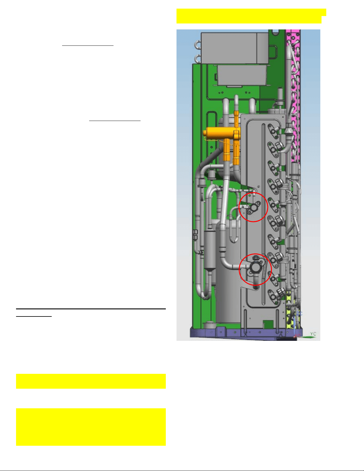
For installation convenience, one set of COMMON
(or MASTER) Service valves have been adopted
into the 3, 4 and 5 zone systems. The common
(master) set of service valves control the common
refrigerant circuitry behind the standard sets of
circuit service valves, where the indoor units are
attached. See the red circles on the picture below.
Picture shows the 5 circuit model where the
Common (Master) valves are located to the left of
the area assigned for the circuit service valves.
Layout for the 3 and 4 circuit models are similar but
the Common (Master) valves are located at the top
of the area assigned for the circuit valves.
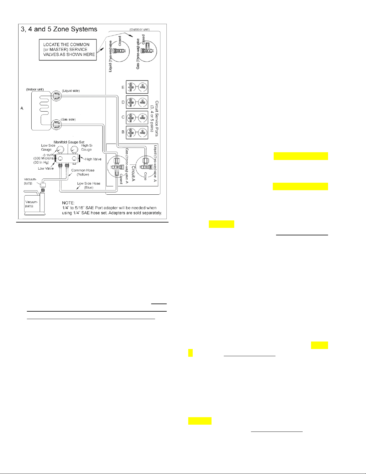
Evacuation using a vacuum pump:
1. Completely tighten ALL brass flare nuts, which
connect the ends of copper refrigerant lines to
the attached indoor units and the circuit service
valves on the outdoor unit using proper torque.
2. Assure that both of the 2-way (Liquid) and 3-way
(Gas) valves for Each Circuit at the outdoor unit
STAY CLOSED as they arrived.
3. Connect the low pressure hose on your gauge
manifold (usually blue) to the 3-way (Gas)
valve’s service port, belonging to circuit A. Note:
First and the largest capacity indoor unit should
always be connected to circuit A as primary.
4. If the manifold gauge set’s hoses have 1/4” SAE
connections, a 1/4” to 5/16” SAE port adapter will
be needed. (Sold Separately).
5. Connect the center hose of the gauge manifold
(usually yellow) to the vacuum pump.
6. Fully open the Low side valve on the low
pressure side of your gauge manifold. Assure
that the High side valve on the high pressure
side of your gauge manifold stays closed.
7. Start the vacuum pump and operate according to
pump manufacturer’s specifications. If your
vacuum pump has a valve, open it as well.
8. Perform vacuuming / evacuation for a minimum
period of 30 minutes and check that the low
pressure gauge indicates a vacuum of 30 in/hg
(500 microns). (A more sensitive vacuum gauge
should be used if available).
9.
If the proper vacuum cannot be achieved within
30 minutes, the vacuum pump should be kept
running for an additional 15 minutes. If after the
additional 15 minutes of operation, the vacuum
still cannot be achieved, there could be a leak at
one or more of the flare pipe connections at
either end of a refrigerant pipes. Leak must be
located and the leaking nut must be tightened
properly before re-vacuuming the circuit.
10. If the vacuum is achieved, close the low side
valve at the low pressure side on your gauge
manifold first and shut the vacuum pump off.
Leave the gauge manifold set and the hoses
connected and recheck the vacuum reading 15
minutes later to assure there is no vacuum loss.
(Very small increase in vacuum level is normal).
11. Circuit A is now dry and free of contaminants. Do
not remove the hose of your gauge manifold set
from the service port.
12. Remove the 2-way (Liquid) Common (Master)
Valve’s brass dust cap. Insert proper size Allen
wrench into the valve core and turn it until it is
back seated. Do not force it once it stops turning.
13. Remove the 3-way (Gas) Common (Master)
Valve’s brass dust cap. Insert proper size Allen
wrench into the valve core and turn it until it is
back seated. Do not force it once it stops turning.
14. Remove the 2-way (Liquid) Valve’s brass dust
cap of circuit A. Insert proper size Allen wrench
into the valve core and turn it counter clockwise
for 1 turn for, wait for 3 seconds and quickly close
the valve by turning it in reverse direction. Check
your low pressure gauge on the manifold to
assure it now indicates positive pressure of
approximately 80 to 120 PSI in your lines.
15. Apply soap-water mixture on both the indoor unit
connections and the outdoor unit connections for
circuit A with a soft brush to check for leakage at
the connecting points of the piping. If you notice
air bubbles, the specific connector has leakage
and must be tightened to stop the leakage.
(An electronic leak detector will be more efficient
to use for this if available).
16. Re-insert proper size Allen wrench into the valve
core of the Liquid Valve (2 way) valve for circuit
A and turn it counter clockwise until it is fully back
seated. Do not force it, once it stops turning.
Repeat the leak checking procedure entirely at
all connections of circuit A. If you find a new leak,
close the 2-way (Liquid) valve you just opened
first and tighten the flare nut at the leaking
connection until the leak is sealed. Reopen the
2-way (Liquid) valve and check again.
17. Remove the 3-way (Gas) Valve’s dust cap for
circuit A. Insert proper size Allen wrench into the
valve core and turn it counter clockwise until it is
fully back seated. Do not force it, once it stops
turning.
18. Power up the system, and run the indoor unit for
circuit A in COOLING mode to assure that all
functions are working.
19. Switch the indoor unit of circuit A to HEAT mode
and assure that all functions are working.
20. Set the temperature on remote to HIGHEST
setting and while the unit is running in heat
mode, check one last time for leaks at all 4
related pipe connections of circuit A. It is easier
to catch even smallest leaks in HEAT mode as
the pressures are much higher.
21. If you discover a leak that cannot be stopped by
tightening the flare nuts at this stage, shut off
both 2 way (liquid) and 3 way (Gas) service
valves, repair the leak properly and start from the
beginning. Please remember you may need to
add fresh refrigerant to the system as a
significant value may be lost at this stage.
22. REPEAT THIS ENTIRE PROCEDURE FOR
THE REMAINING CIRCUITS, B, C, D, E. Skip
if a circuit is not being utilized by an indoor
unit. In case an indoor unit is added in the
future, the same procedure should be
followed for that added circuit entirely.
5.4.3. Adding refrigerant if the pipe length
exceeds standard factory pre-charge amount:
Your system is pre-charged with sufficient
refrigerant to work properly, according to an average
length of 7.5 meter (25 feet) piping for each of the
available circuits (example a 4 zone system can
have total piping length for all zones added together
of 30 meters (100 feet) max. If your total piping
length exceeds this limit, additional refrigerant must
be added to the system to compensate for the
difference.
Procedure:
PROCEDURE FOR 2, 4 AND 5 ZONE OUTDOOR
UNITS ARE DIFFERENT FROM 2 ZONE MODELS.
See Specific instructions below for each type as it
applies to your specific model.
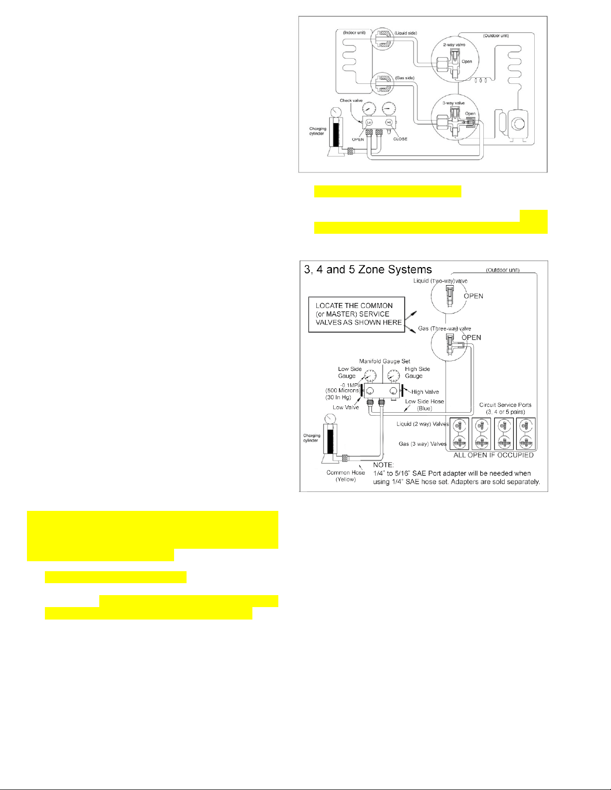
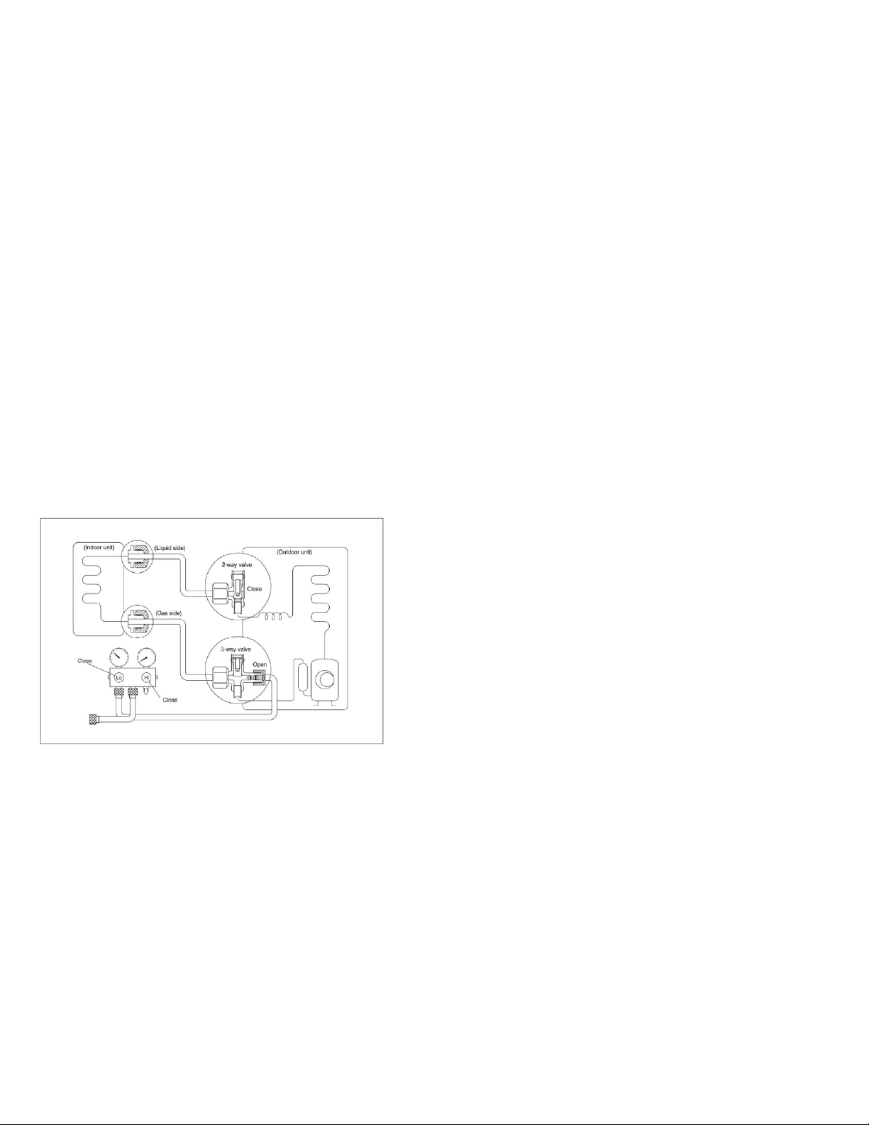
1. For Dual (2 Zone) systems, connect the low
pressure hose on your gauge manifold (usually
blue) to the 3-way (Gas) valve’s service port of one
of the occupied circuits (Circuit A preferred). See
below drawing.
2. For 3, 4 and 5 zone systems, connect the low
pressure hose from the gauge manifold set (this is
usually the blue hose on most sets) to the 3-way
(Gas) service valve of the Common (master) circuit.
See below drawing
3. Connect the center hose of the gauge manifold
(usually yellow) to the refrigerant container (this is
usually the yellow hose on most sets). Refrigerant
410A can only be charged in Liquid form while the
container must be inverted (upside down). Note
that all 2-way (Liquid) and 3-way (Gas) valves for
all “occupied” circuits where an indoor unit is
attached must be in the open position. Additionally,
for 3, 4 and 5 circuit models, the common (master)
2-way (Liquid) and 3-way (Gas) valves must also
be in open position.
4. The air trapped in the gauge manifold and the
hoses must be purged out. Use the pressure from
the system to purge the low side hose, by briefly
loosening its connection at the gauge manifold for
a second. Next, open the valve of the refrigerant
container to pressurize the center hose and loosen
the connector of the center hose at the gauge
manifold for a second and purge that line.
5. Determine the volume of the additional refrigerant
added into the system for the additional piping.
6. Set the refrigerant container on an electronic
charging scale and record the weight (or zero-out
the scale depending on the scale used).
7. Start all indoor units attached to the system in
cooling mode and lower the set points on each of
their controllers to the minimum setting so the
system will not shut off during the procedure.
8. Refrigerant can now be added to the system, open
the low side valve at the low pressure side of the
gauge manifold set to start charging the unit with
liquid refrigerant. Please remember to nurse the
refrigerant in slowly by controlling the low side
valve at the Low pressure side of your gauge
manifold (open for 3 seconds and close for 10
seconds for the system to digest each load). Keep
track of the refrigerant being added into the system
(do not overcharge the system).
9. Once the correct charge has been added to the
system, close the low side valve at the low
pressure side of the gauge manifold set and check
the operating pressure. Keep running the system
continuously for 20 minutes and record the
pressure reading along with the indoor and outdoor
temperature readings for future reference. The
system is now charged and can be shut off.
10. Close the valve on the refrigerant container and
disconnect the hose from the manifold set, also
disconnect the hose from the 3-way (Gas) valve
where it is attached to the unit and replace and
torque all brass dust caps.
Be sure to use a torque wrench to tighten the
service port caps to a torque 18N·m (13.27 ft·lbs).
Always leak check all service ports after servicing
the refrigerant system.
5.5 Adding or replacing the refrigerant after
a refrigerant loss is discovered:
Please note: R410a is a blended and isotropic
refrigerant. If refrigerant is lost from your system in
significant amounts (exceeding 15% of the total
volume), the remaining refrigerant may no longer
contain the proper original ratio of the blend.
Therefore system must be entirely evacuated and
recharged with fresh refrigerant. If the system is
determined to have lost only a small amount of
refrigerant, it can be topped off using the same
procedure as covered above in paragraph 5.4.3,
until proper operating pressures and performance
are obtained. Prior to recharging refrigerant after a
leak is discovered, the leak itself must be located
and repaired to avoid the repeated refrigerant
losses. A well-sealed system will never need
refrigerant to be recharged as it stays as a sealed-
closed system entirely. Below procedure explains
complete evacuation and fresh refrigerant recharge
procedure.
Procedure
1. Keep all attached indoor units connected and
assure that all of the brass flare nuts at all pipe
connections both at the indoor and outdoor unit
connectors are tight and leak free.
2. Assure ALL of the 2-way (Liquid) and 3-way (Gas)
service valves of the utilized circuits (where an
indoor unit is attached) are fully open.
3. For 3, 4 and 5 zone systems, also assure that both
of the Common (Master) 2-way (Liquid) and 3-way
(Gas) service valves are fully open.
4. Assure that the 2-way (Liquid) and 3-way (Gas)
service valves of any unused circuit are fully closed.
5. Next step is different for 2 zone and 3/4/5 zone
systems. See 5a. and 5b. accordingly:
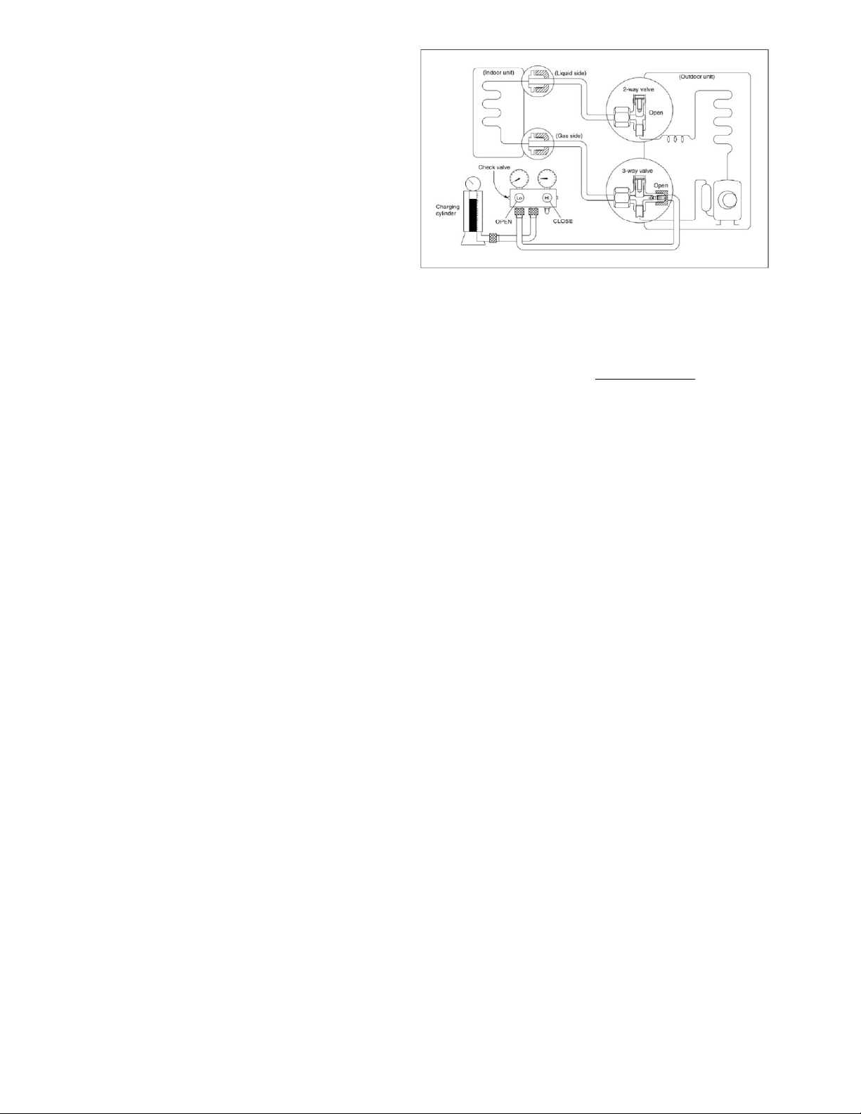
a. If servicing a Two Zone (dual split) system,
connect the low pressure hose on your gauge
manifold (usually blue) to the 3 way (Gas)
valve’s service port, belonging to circuit A.
Additionally connect the high pressure hose on
your gauge manifold (usually red) to the 3 way
(Gas) valve’s service port, belonging to circuit
B. (Ignore this if there is only one indoor unit
attached to the system. Single indoor units
should always be attached to circuit A.). Fully
open both the Low side valve on the low
pressure side and the High side valve on the
high pressure side of your gauge manifold.
(Keep the High side valve at the High pressure
side of the gauge manifold closed if there is
only a single indoor unit attached to the system)
If the manifold gauge set’s hoses have 1/4”
SAE connections, two 1/4” to 5/16” SAE port
adapters will be needed, one for each circuit.
See below drawing.
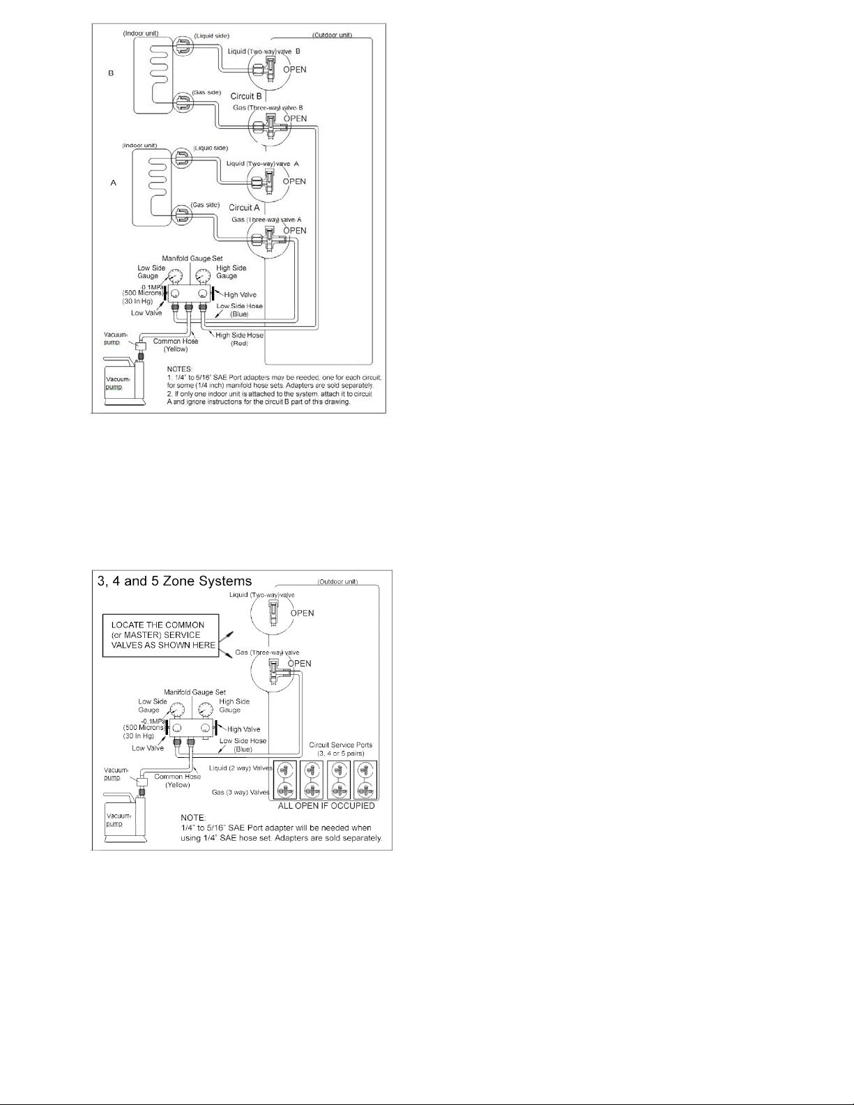
b. If servicing a 3, 4 or 5 zone system, connect
only the low pressure hose on your gauge
manifold (usually blue) to the 3 way (Gas)
valve’s service port, belonging to the
COMMON or the MASTER Circuit. Fully open
the Low side valve on the low pressure side of
your gauge manifold only. See below drawing.
6. Connect the center hose of the gauge manifold
(usually yellow) to the vacuum pump.
7. Start the vacuum pump and operate according to
pump manufacturer’s specifications.
8. Perform vacuuming/evacuation for a minimum total
period of 30 minutes for each attached circuit
added together (example 90 minutes for a system
with 3 indoor units) and check that the low pressure
gauge indicates a vacuum of 30 in/hg (500
microns). (A more sensitive vacuum gauge should
be used if available).
9. If the proper vacuum cannot be achieved within this
time frame, the vacuum pump should be kept
running for an additional 1 hour. If after the
additional 1 hour of operation the vacuum still
cannot be achieved, there could be a leak at one
or more of the flare pipe connections at either end
of a refrigerant pipe. Leak must be located and the
nut must be tightened properly.
10. If the vacuum is achieved, close the valve(s) on
your gauge manifold set first and shut the vacuum
pump off. Leave the gauge manifold and the hose
connected and recheck the vacuum reading 30
minutes later to assure there is no vacuum loss.
(Small insignificant increase in the vacuum level is
normal).
11. ALL occupied circuits as well as the outdoor unit
are now dry and free of contaminants. Do not
remove the hose of your gauge manifold set from
the service port(s).
12. Connect the middle hose from the manifold set to
the refrigerant container (this is the yellow line on
most sets). With refrigerant 410A the container
must be inverted (upside down) when adding the
refrigerant.
13. The air in the gauge hoses needs to be purged out.
Use the pressure from the system to purge the low
side line, loosen the connection on the manifold for
a second. Next open the valve on the refrigerant
container to pressurize the line, now loosen that
hose at the manifold for a second and purge that
line.
14. Set the refrigerant container on an electronic
charging scale and record the weight or zero the
scale depending on the scale used.
15. Next determine the refrigerant charge to be added.
The total standard factory charge volume is written
on the side specification label of your outdoor unit.
Consider additional volume for extended line sets.
16. Refrigerant can now be added to the system. The
first step will be performed when the system is
powered off entirely. Open the low pressure valve
on the gauge manifold set to start charging the unit
with liquid refrigerant, Please remember to nurse
the refrigerant in slowly by controlling the low
pressure valve at the Low side of your gauge
manifold (open for 3 seconds and close for 10
seconds). Keep track of the refrigerant being
added to the system (do not overcharge the
system).
17. If the system stops accepting refrigerant before the
entire intended volume is charged, close the low
pressure valve on the Low pressure side of your
manifold. Wait for 15 minutes and open Low
pressure side of your manifold and try again,
repeat this several times until no more or only very
little refrigerant can be charged this way.
18. Close the Low pressure side of your manifold .Start
the system with all indoor units attached running in
cooling mode and lower the set points on each of
their controllers to the minimum setting so the
system will not shut off during the procedure.
19. Open the low pressure valve on the gauge
manifold set to start charging the unit with liquid
refrigerant for the remaining amount. Please
remember to nurse the refrigerant in slowly by
controlling the low pressure valve at the Low side
of your gauge manifold (open for 3 seconds and
close for 10 seconds). Keep track of the refrigerant
being added into the system until the entire
intended volume is charged. (do not overcharge
the system).
20. The correct charge has been added to the system
close the low pressure valve on the gauge manifold
set and record the operating pressure. The system
is now charged and the unit can be shut off. Close
the valve on the refrigerant container and
disconnect the hose from the manifold set, also
disconnect the hose from the 3 way valve and
replace and torque all caps.
21. Be sure to use a torque wrench to tighten the
service port cap to a torque 18N·m (13.27 ft·lbs).
Always leak check after servicing the refrigerant
system.
5.6 Procedure to remove, replace or service
the refrigeration circuit of an indoor unit by
Pumping down the system (isolating the
refrigerant charge in the condensing unit):
Procedure:
1. With all indoor units are running in cooling mode
and their controllers are set to a low setting,
remove all brass dust caps from the 3-way (Gas)
and 2-way (Liquid) valves of the circuit of the indoor
unit that is to be removed.
2. Assure the Low and High side valves of your gauge
manifold set are both closed. Attach the low
pressure hose of the manifold gauge to the 3-way
(Gas) service valve port of that circuit. Purge the
air from that hose by loosening the hose where it
connects to the gauge manifold for a second. Be
sure to record the operating pressure, you will
need to know this when you complete the service
on the indoor unit and restart the system. Now get
prepared to close both 3-way (Gas) and 2-way
(Liquid) valves on the unit. Also be prepared to shut
the power off to the outdoor unit entirely.
3. While the system is running, first close the 2-way
(Liquid) valve entirely and monitor the low pressure
gauge. The pressure will start to drop quickly.
4. Keep operating the unit in the cooling mode until
pressure reading on the low pressure gauge of the
manifold drops to zero. At this moment, quickly
close the 3-way (Gas) valve and then immediately
disconnect the power to the outdoor unit. Running
the compressor in a vacuum for a long time could
damage the motor windings. Note that units with
extended lines and additional refrigerant charge
may not be able to pump down the line entirely.
This is because the outdoor unit can only store a
certain amount of refrigerant and this is normal (the
amperage of the compressor will have to be
monitored in this case). There may be little
pressure left in the system. This is normal. The
indoor unit is now ready to be removed and
serviced.
5. Remember to evacuate / vacuum the circuit after
the indoor unit is reinstalled as per the procedures
covered above entirely. Check for leaks as stated
above for new installations. Open both 3-way (Gas)
and 2-way (Liquid) valves to release the refrigerant
to the serviced circuit. Test for leaks again and
proper operation. If you notice less pressure
reading than recorded before the removal of the
indoor unit, top off with a little additional refrigerant.
5.7 Evacuation after servicing the outdoor
unit refrigeration circuit
SEEPARAGRAPH5.5ANDFOLLOWTHESAME
PROCEDURE.
NOTE:Frequentservicingandattachmentofhoses
totheserviceports,maydamagethesealsofthe
Schradervalvesinsideofthoseserviceports.Always
checkforleaksateachoftheserviceportsafterthe
gaugemanifoldhoseisdisconnectedfromthatport.
Ifyounoticealeakattheserviceport,theSchrader
valve core will need to be replaced. There is a
specialtoolthatcanbeusedtoreplacetheSchrader
valvecorewithoutlosingrefrigerant.Referthisto
yourservicecompany.
Refrigerant is Toxic and can create serious frost
bitesonyourskin.Alwaysassuretowearsafety
gear to protect your skin and eyes. Seek medical
assistanceincaseofaccidents.
Mostinstallationsandserviceareregulatedbylocal
regulationsandbuildingcodes.Someormostofthe
workoutlineshereinmayrequireproperpermitting
from the building department. Always assure to
followallapplicablerulesandregulations.
6. Electronic Function
6.1 Abbreviation
T1: Indoor ambient temperature
T2: Coil temperature of indoor heat exchanger at
middle circuit.
T2B: Coil temperature of indoor heat exchanger at
outlet. (This sensor is located in the outdoor unit)
T3: Pipe temperature of outdoor heat exchanger
T4: Outdoor ambient temperature
T5: Compressor discharge temperature
6.2 Electric control working environment.
6.2.1 Input voltage: 230V.
6.2.2 Input power frequency: 60Hz.
6.2.3 Indoor fan normal working amp. is less than
1A.
6.2.4 Outdoor fan. Normal working amp. is less than
1.5A.
6.2.5 Four-way valve normal working amp. is less
than 1A.
6.3 Main Protection
6.3.1 Three Minute Delay at restart of the
compressor.
---- 1 min delay for the 1
st
time start-up and 3 minute
delay for all subsequent starts.
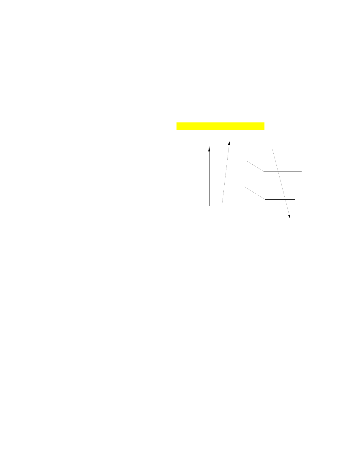
6.3.2 Temperature protection of compressor
discharge.
As the compressor discharge temperature rises, the
running frequency will be limited as per the following
rules:
----If 105 (221 ) ≦ T5 <110 (230 ), keep the
current frequency.
----If the temperature increases and T5≧110 (230
), decrease the frequency to the next lower level
every 2 minutes till reaching F1.
---If T5≧115 (239 ) for 10 seconds, the
compressor will stop and restart when T5<90 (194
).
6.3.3 Fan Speed is out of control.
---- When outdoor fan speed is lower than 100RPM
or higher than 2400RPM for 60 seconds, the system
stops and LED displays
E8 failure.
6.3.4 Inverter module Protection.
----Inverter module protection safeguards the
system against current, voltage and temperature
abnormalities. If these protections are triggered, the
corresponding code will display on indoor unit LED
and system will stop. The unit will recover after the
cause of the error disappears, and following a
minimum 3 minute time delay.
6.3.5 Low voltage protection
VOLTAGE
No limit
VOLT_LTM_FREQ1_ADD
VOLT_LTM_FREQ2_ADD
Note: if the low voltage protection is triggered and
not restored within 3minutes, the system will keep
the protection active after the restart.
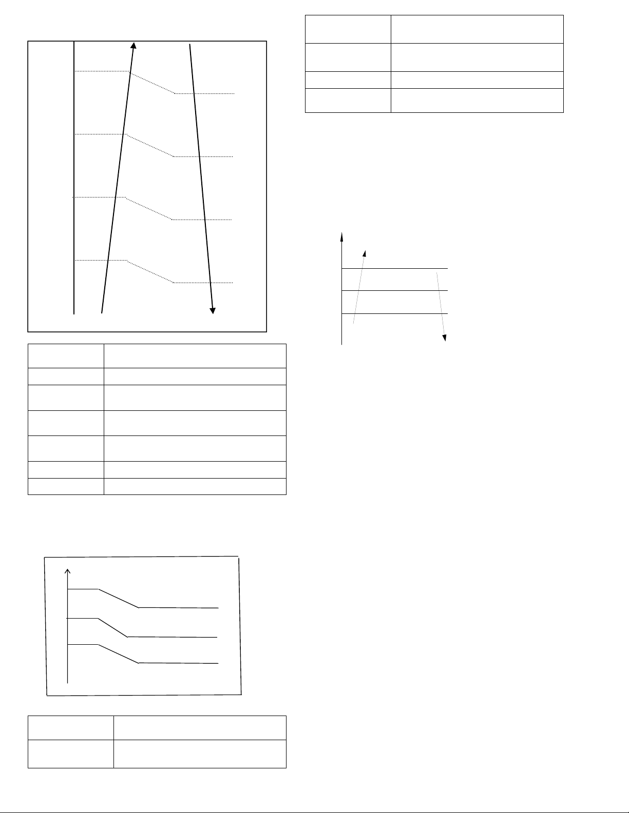
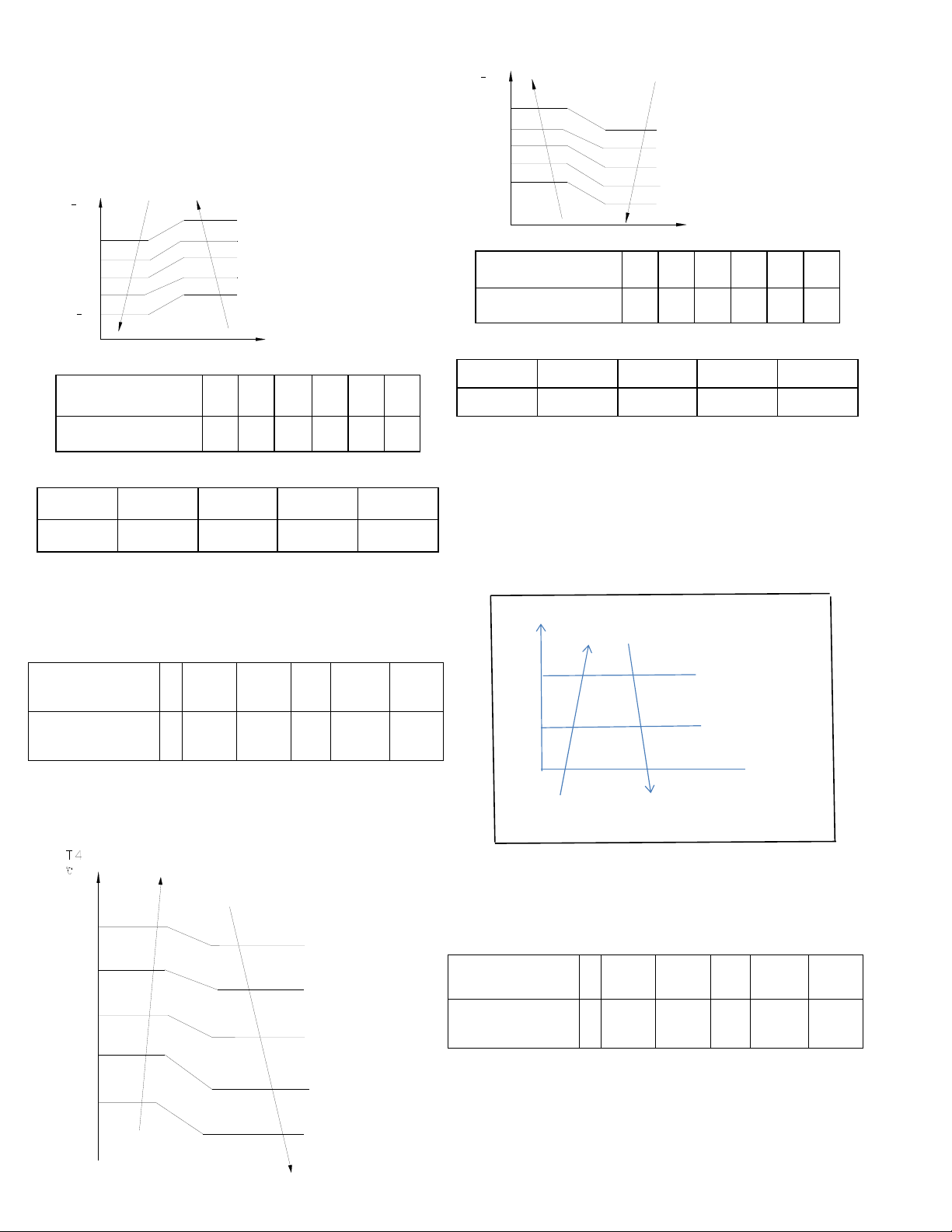
6.3.6 Compressor current limit protection
Temperature interval.of current limit is same as the
range of the T4 limited frequency.
Cooling mode:
CoolReturnI The difference between limit
current and quit current.
CoolT4Zone5I
Cooling T4≥50℃ limit current value
CoolT4Zone4I
Cooling 49>T4≥45℃ limit current
value
CoolT4Zone3I
Cooling 44>T4≥41℃ limit current
value
CoolT4Zone2I
Cooling 40﹥T4≥33℃ limit current
value
CoolT4Zone1I
Cooling 32>T4℃ limit current value
CoolStopI Cooling stop protection current value
Heating mode:
℃
15
14 HeatT4Zone4I
10
9 HeatT4Zone3I
6
5 HeatT4Zone2I
HeatT4Zone1I
HeatReturnI
The difference between limit
current and quit current.
HeatT4Zone4I
Heating T4≥15℃limit current
value
HeatT4Zone3I
Heating14>T4≥10℃ limit
current value
HeatT4Zone2I
Heating9>T4≥6℃ limit current
value
HeatT4Zone1I
Heating5>T4 limit current value
HeatStopI
Heating stop protection current
value
6.3.7 Indoor / outdoor unit communication
protection
If the indoor units cannot receive the feedback
signal from the outdoor units for 2 minutes, the
system will stop and display the failure.
6.3.8 High condenser coil temp. protection.
6.3.9 Outdoor unit freezing protection
When T2<4℃ for 250 seconds or T2<0℃, the
indoor unit capacity demand will be zero and
resume to normal when T2>8℃ and the duration of
protection is no less than 3 minutes.
6.3.10 Oil return
Running rules:
1. If the compressor frequency stays lower than
setting frequency for setting time, the system will
rise the frequency to the setting frequency for
setting time and then resume to former frequency.
2. The EXV will keep 300p while the indoor units
will keep the current running mode.
If the outdoor ambient is higher than setting
frequency during the oil return cycle, the system will
quit oil return cycle.
6.3.11 Low outdoor ambient temperature
protection
When compressor is off, if T4 is lower than -
35℃.for 10s, the system will stop and display
“LP”.
When compressor is on, if T4 is lower than -
40℃.for 10s, the system will stop and display
“LP”.
When T4 is not lower than -32℃.for 10s, the unit
will exit this protection.
T3
Resume
Off
Decrease
Hold
℃CoolT4Zone5I
50
49
45
CoolT4Zone4I
44
41
40
CoolT4Zone3I
33
32
CoolT4Zone2I
6.4 Control and Functions
6.4.1 Capacity Request Calculation
Total capacity Request=Σ(Norm code × HP) /10 +
correction
Cooling mode:
T1 Ts
3
1
1
e
c
a
4
2
0
2
3
0
1
f
d
b
Capacity area a b c d e f
Norm code (N) 3 2 1.5 1 0.5 0
Model 9K 12K 18K 24K
HP 1.0 1.2 1.5 2.5
Note: The final result is integer.
According to the final capacity request to
confirm the operating frequency, as per the
following table.
Frequency (Hz)
0
COO
L_F1
COO
L_F2
…
…
COOL
_F24
COO
L_F2
5
Amended
capacity
demand.
0 1 2
…
…
24 25
Meanwhile the maximum running frequency will be
adjusted according to the outdoor ambient temp.
43
41
38
T4LimFre1_ADD
No limit
T4LimFre2_ADD
T4LimFre3_ADD
42
39
37
49
46
T4LimFre4_ADD
T4LimFre5_ADD
48
45
Heating mode
T1 Ts
4
0
a
3
1
-1
3
1
2
0
b
c
d
e
f
2
Capacity area a b c d e f
Norm code (N) 3 2 1.5 1 0.5 0
Model 9K 12K 18K 24K
HP 1.0 1.2 1.5 2.5
Note: The final result is an integer.
Then modify it according to T2 average
(correction):
Note: Average value of T2:(Sum T2 value of all
indoor units) / (number of indoor units)
℃
T2 average
Decrease frequency
47
Keep frequency
40 Increase frequency
According to the final capacity request to
confirm the operating frequency, as per the
following table.
Frequency (Hz)
0
HEAT
_F1
HEAT
_F2
…
HEAT
_F24
HEAT
_F25
Amendatory
capacity
demand.
0 1 2 … 24 25
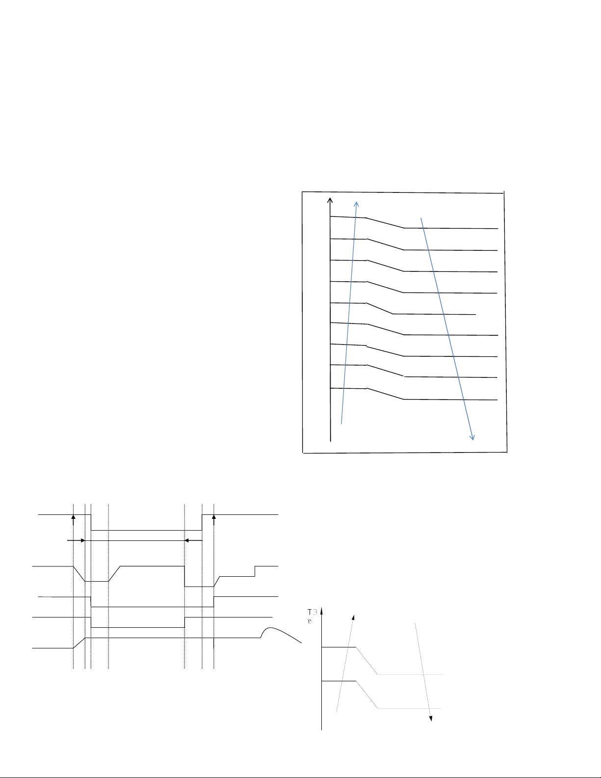
6.4.2 Defrosting control
Condition of defrosting:
If any one of the following items is satisfied, system
will enter into the defrosting cycle.
After the compressor starts up and keeps running,
marks the minimum value of T3 from the 10th
minute to 15th minute as T30.
1) If the compressor’s cumulate running time is up
to 29 minutes and T3< TCDI1, T3+
T30SUBT3ONE ≦ T30.
2) If the compressor’s cumulate running time is up
to 35 minutes and T3< TCDI2, T3+
T30SUBT3TWO ≦ T30.
3) If the compressor’s cumulate running time is up
to 40 minutes and T3< -24C for 3 minutes.
4) If the compressor’s cumulate running time is up
to 120 minutes and T3<-15℃.
Condition of ending defrosting cycle:
If any one of the following items is satisfied, the
defrosting will finish and the system will switch to
normal heating mode.
----T3 rises to be higher than TCDE1℃.
----T3 keeps to be higher than TCDE2℃ for 80
seconds.
----The system has run for 10 minutes in defrosting
mode.
Defrosting action:
off on
Cool‐F9
10S 30S
TimeA
10S
4‐wayvalve defrosting Defrostingover
compressor
Indoorfan
Outdoorfan
EXVopen
frequency
Max10minutes
frequency
Compressorstops
off
Anti‐coldcontrol
off
480P 480Pfor240s
Condition of ending defrosting:
If any one of following items is satisfied, defrosting
will stop and the system will switch to normal heating
mode.
① T3 > TempQuitDefrost_ADD ℃;.
② The defrosting time reaches 10min.
③ Turn to other modes or off.
6.4.3 Outdoor fan control
6.4.3.1 Cooling mode
Normally the system will choose the running fan
speed according to ambient temperature:
Outdoo
r
℃
45
43 Supper high fan speed
28
26 High fan speed
25
23 Middle fan speed
22
20 Low fan speed
19
17 Supper low fan speed
10
9 Breeze fan speed
0
-1 F fan speed
-5
-6 G fan speed
-10
-11 H fan speed
I fan speed
When low ambient cooling is active:
Outdoor fan speed control logic (low ambient
cooling)
When T4 <15 ℃ (59 ℉) and T3 < 30 ℃ (86 ℉), the
unit will enter into low ambient cooling mode. The
outdoor fan will choose speed according to T3.
When T3≥38 ℃ (100.4 ℉) or when T4≥20 ℃ (68
℉), the outdoor fan will choose the speed according
to T4 again.
38
Exit low ambient cooling
mode
, run with high fan
for 1 minute
Low
30
27
23
off
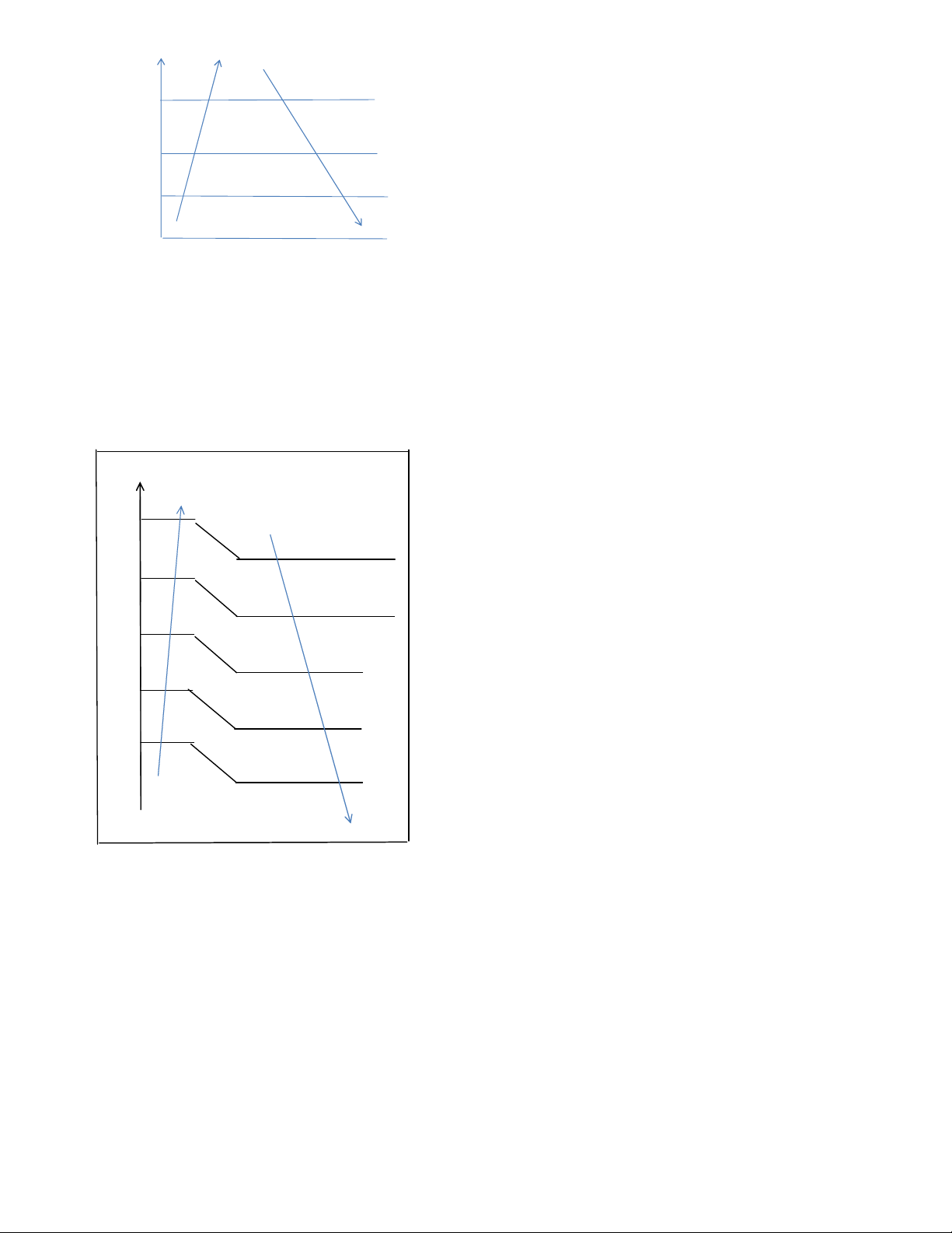
T3
Increase fan speed increase
Keep current fan speed
Decrease fan speed
Fan stop
LowCoolT3_ON
LowCoolT3_Down
LowCoolT3_OFF
6.4.3.2 Heating mode
Normally the system will choose the running fan
speed according to ambient temperature:
Outdoor temperature℃
21
Breeze fan speed
19
18
Supper low fan speed
16
15
Low fan speed
13
12
Middle fan speed
10
0
High fan speed
-2
Supper high fan speed
6.4.4 Electronic Expansion Valve (EXV)
Control
1. EXV will be fully closed when the power is turned
on. Then the EXV will be on standby with 350P open
and will open to target angle after compressor starts.
2. EXV will close with -160P when compressor stops.
Then EXV will be standby with 350P open and will
open to target angle after compressor starts.
3. The action priority of the EXVs is A-B-C-D-E.
4. Compressor and outdoor fan start operation only
after EXV is initialized.
6.4.4.1 Cooling mode
The initial open angle of EXV is depends on indoor
model size, and the adjustment range is 100-400p.
When the unit starts to work for 3 minutes, the
outdoor will receive indoor units’ capacity demand
(T2B) information and calculate their average. After
comparing each indoor unit’s T2B with the average,
the outdoor will give the following modification
commands:
If the T2B > average, the relevant valve needs
additional 16p to open;
If the T2B= average, the relevant valve’s open range
remains;
If the T2B < average, the relevant valve needs
additional 16p to close.
This modification will be carried out every 2 minutes.
6.4.4.2 Heating mode
The initial open angle of EXV is depends on indoor
model size, and the adjustment range is 150-350p.
When the system starts to work for 3minutes, the
outdoor unit will receive indoor units’ capacity
demand (T2) information and calculate their average.
After comparing each indoor unit’s T2 with the
average, the outdoor unit gives the following
modification commands:
If the T2 > average+2, the relevant valve needs
additional 16p to close;
If average+2≥the T2≥ average-2, the relevant
valve’s open range remains;
If the T2 < average-2, the relevant valve needs
additional 16p to open.
This modification will be carried out every 2 minutes.
6.4.5 Four-way valve control
In heating mode, four-way valve is activated. In
defrosting, four-way valve operates according to the
defrosting action. In other modes, four-way valve is
deactivated. When switching from the heating mode
to other modes, the four-way valve will be
deactivated, after the compressor stays off for 2
minutes. In case of any failure or protection
activation (not including discharge temperature
protection or high and low pressure protection), four-
way valve immediately deactivates.
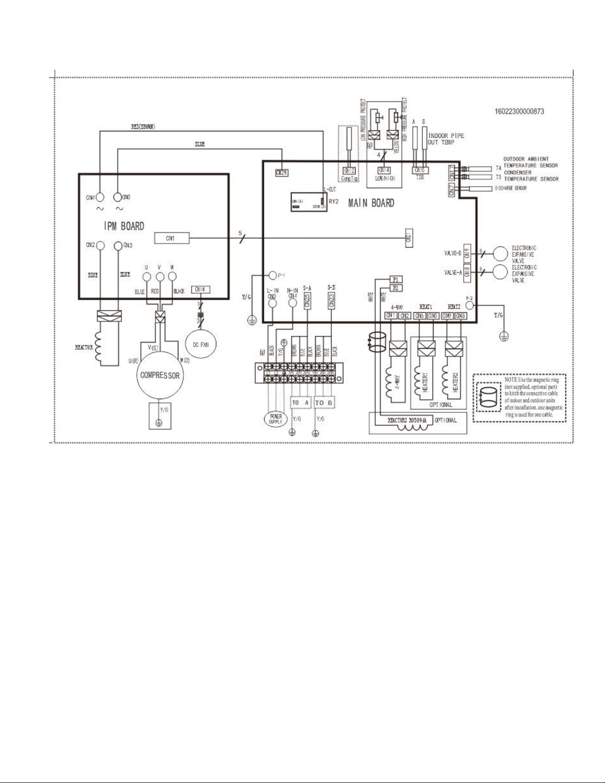
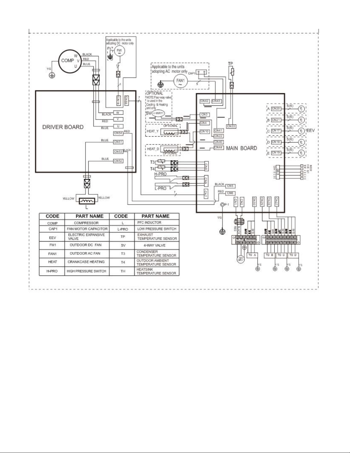
7. Wiring Diagrams
8.1 Wiring diagram of DUAL (2) Circuit Outdoor Unit
YN020GMFI22M2D
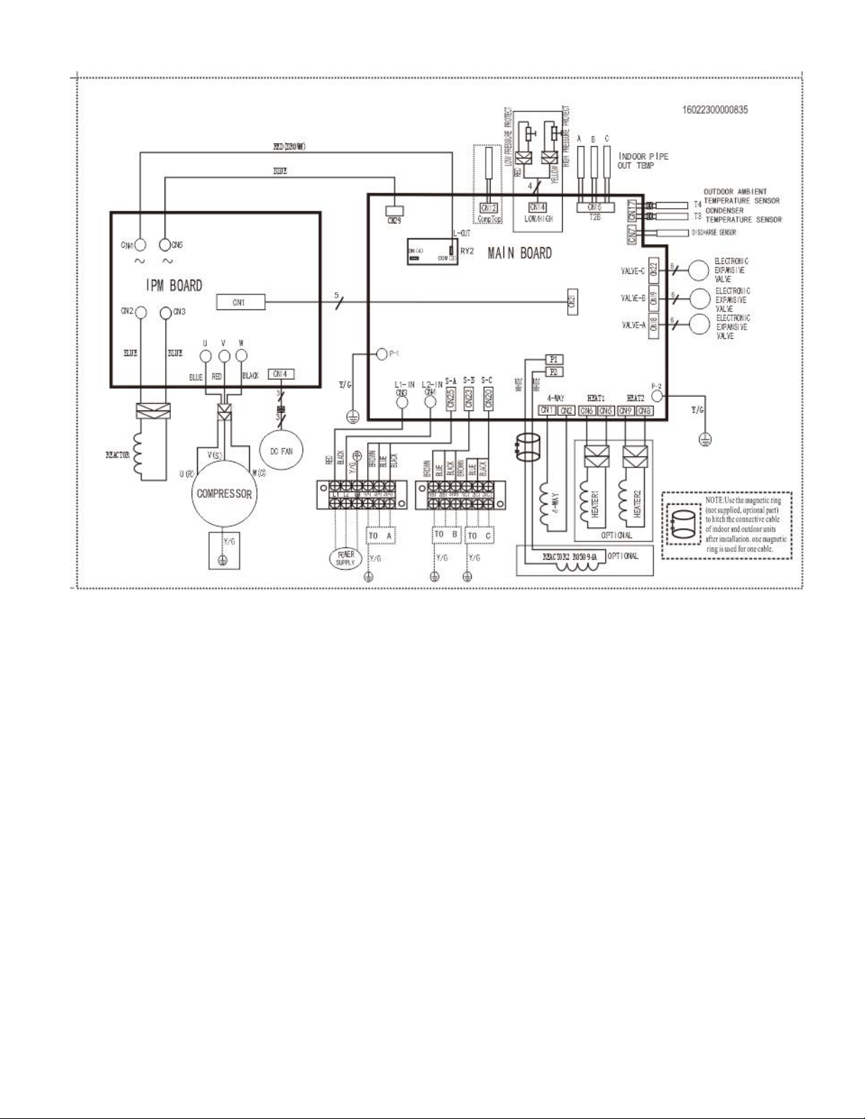
8.2 Wiring diagram of TRIPLE (3) Circuit Outdoor Unit
YN030GMFI22M3D
8.3 Wiring diagram of QUAD (4) Circuit Outdoor Unit
YN040GMFI22M4D
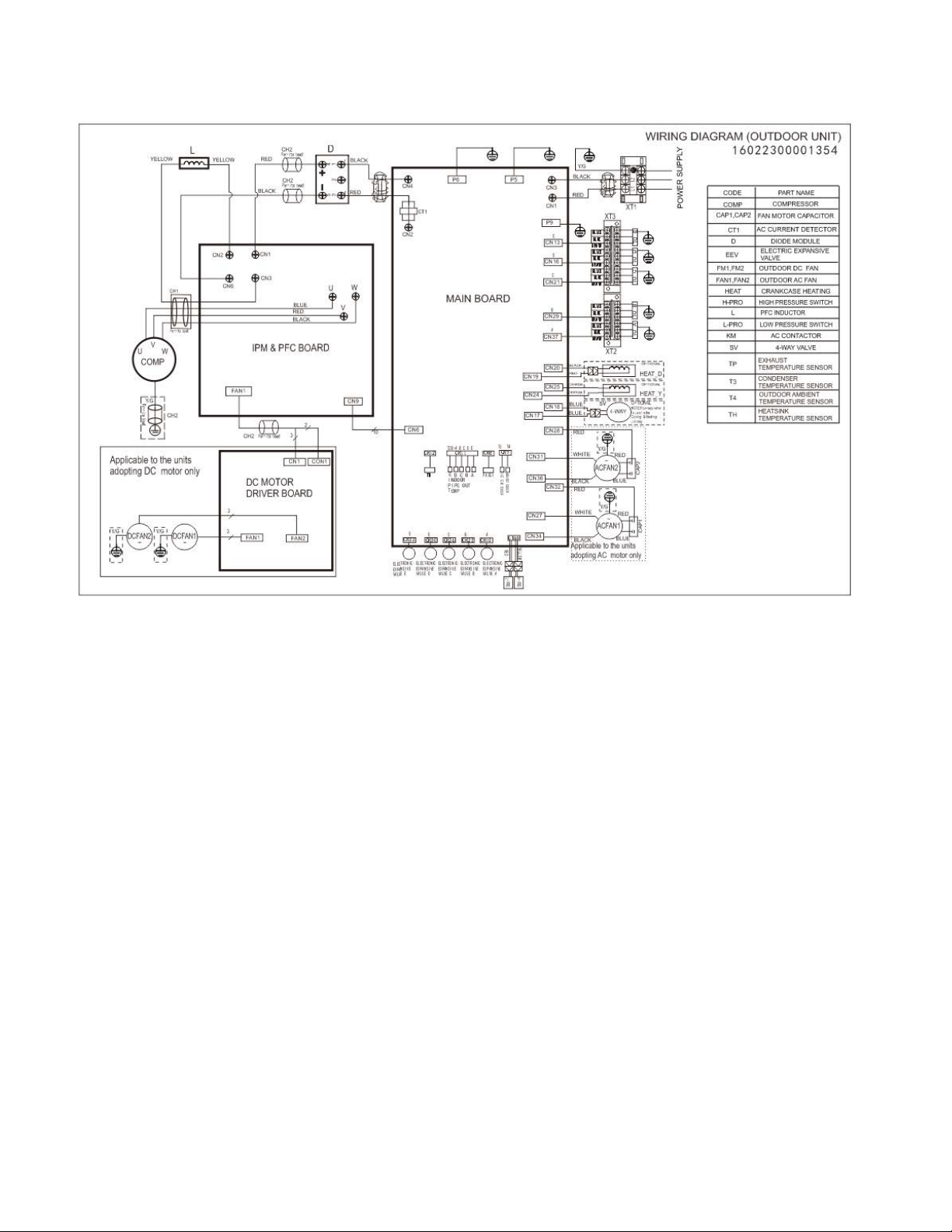
8.4 Wiring diagram of QUINT (5) Circuit Outdoor Unit
YN050GMFI22M5D
8. Troubleshooting
8.1Safety
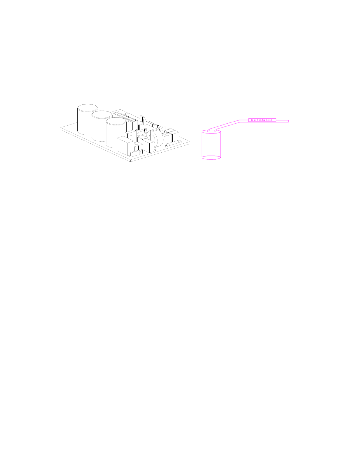
Because there are high power capacitors on PCB and related circuits in outdoor unit, even after
shutting down the power supply, risk of electrocution still exists. Do not forget to discharge the electrical
power in these capacitors.
Use a 25~40 W bulb or resistor with resistance value of about 1500 ohm to 2000 ohm to discharge the
power in the capacitors.
.
Electrolytic Capacitors
(HIGH VOLTAGE! CAUTION!)
The voltage in P3 and P4 in outdoor PCB is high voltage about 310V
The voltage in P5 and P6 in outdoor PCB is high voltage about 310V

8.2 Indoor Unit Error Display
For 2015 or earlier Floor Console Models
FB012GMFI16HLD (2015 or earlier)
Operation Timer De-frost
Failure
★
X X Indoor room temperature sensor (T1 ) malfunction
X X
★
Evaporator coil temperature sensor (T2) malfunction
X
★
X Communication malfunction between indoor and outdoor units
★
X Low ambient temperature cut off in heating
★ ★
X Indoor unit EEPROM parameter error
X
★
Outdoor fan speed has been out of control
★
X
★
Inverter module (IPM) malfunction
★
★ ★
Outdoor temperature sensor(coil sensor T3 or ambient temperature
sensor T4) malfunction or Outdoor unit EEPROM parameter error
★
X Compressor top high temperature protection (OLP)
★ ◎
X Compressor drive protection
★
X
Indoor units mode conflict
★
★
Indoor fan speed has been out of control
◎
X X
In standby mode
●
◎ ◎
In force cooling mode
★flashat5Hz,light,Xextinguished,◎flashat0.5Hz

For 2015 or earlier Concealed Duct / Cassette / Floor Ceiling Models:
RB012GMFI16HLD, RB018GMFI16HLD (2015 and earlier)
CB012GMFI16HLD, CB018GMFI16HLD (2015 and earlier)
UB012GMFI16HLD, UB018GMFI16HLD (2015 and earlier)
Operation Timer
De-
frost
Alar
m
Failure
Display
ODU Error
code
★
X X X
Indoor room temperature sensor (T1
) malfunction
E0 ——
X X
★
X
Evaporator coil temperature sensor
(T2) malfunction
E1 ——
X
★
X X
Communication malfunction
between indoor and outdoor units
E2 E2
X X X
★
Water-level alarm malfunction E3 ——
★ ★
X X
Indoor unit EEPROM parameter
error
E4 ——
★
X X
Inverter module (IPM) malfunction E5 P6
★
X X
Outdoor temperature sensor(coil
sensor T3 or ambient temperature
sensor T4) malfunction or Outdoor
unit EEPROM parameter error
E6 E0,E4
★
★
X
Outdoor fan speed has been out of
control
E7 E8
★
X
Indoor fan speed has been out of
control
F5 ——
★
X
Over-voltage or under-voltage
protection
P0 E5
★
X
X
Compressor top high temperature
protection (OLP)
P1 P0
★ ★ ★
X Current overload protection P2 P3
★ ◎
X X Compressor drive malfunction P4 ——
★
X
Indoor units mode conflict P5 ——
★ flash at 2.5Hz, light, X extinguished,,◎flashat0.5Hz

For 2015 or earlier Wall Mount Models
WB009GMFI16HLD, WB012GMFI16HLD, WB018GMFI16HLD (2015 and earlier)
De-frost Time
r
Auto O
p
eratio Failure Dis
p
la
y
Indoor unit EEPROM parameter error E0
★ ★ ★ ★
Communication malfunction between indoor and
outdoor units error
E1
★ ★
Zero-crossing signal detection error E2
★ ★
Indoor fan speed has been out of control E3
X
X
★
Outdoor temperature sensor(coil sensor T3 or
ambient temperature sensor T4) malfunction or
Outdoor unit EEPROM parameter error sensor
E5
★
Indoor room temperature sensor(room sensor T1
or coil sensor T2
)
malfunction
E6
★
★ ★
Outdoor fan speed has been out of control E7
X X
★
Inverter module (IPM) malfunction P0
X
★
Over-voltage or under-voltage protection P1
X X
★
Compressor top high temperature protection
(OLP)
P2
X
★
Low ambient temperature cut off in heating P3
X
★ ★
Compressor drive malfunction P4
X
★ ★
Indoor units mode conflict P5

For All 2016 and newer Models: Wall Mount, Concealed Duct / Cassette / Floor Console / Floor
Ceiling):
1) Wall Mounted:
WS009GMFI22HLD, WS012GMFI22HLD, WS018GMFI22HLD, WS024GMFI22HLD.
2) Ceiling Concealed:
RB009GMFILDFHD, RB012GMFILDFHD, RB018GMFILDFHD, RB024GMFILDFHD.
3) Cassette:
CB009GMFILDFHD, CB012GMFILDFHD, CB018GMFILDFHD, CB024GMFILDFHD.
4) Floor Console:
FB009GMFILDFHD, FB012GMFILDFHD.
5) Floor / Ceiling:
UB018GMFILDFHD, UB024GMFILDFHD.
Operation lamp
Timer
lamp
Display LED STATUS
ODU
Error
★ 1 time
X E0 Indoor unit EEPROM parameter error
——
★ 2 times
X E1 Communication malfunction between indoor and outdoor units
E2
★ 4 times
X E3 Indoor fan speed has been out of control
——
★ 5 times
X E4 Indoor room temperature sensor (T1 ) malfunction
——
★ 6 times
X E5
Evaporator coil temperature sensor (T2) malfunction
——
★ 8 times
X EE Water-level alarm malfunction
★ 1 times
F0 Current overload protection
——
★ 2 times
F1 Outdoor ambient temperature sensor (T4 ) malfunction
E4
★ 3 times
F2 Condenser coil temperature sensor (T3) malfunction
E4
★ 4 times
F3 Compressor discharge temperature sensor (T5) malfunction
E4
★ 5 times
F4 Outdoor unit EEPROM parameter error
E0
★ 6 times
F5 Outdoor fan speed has been out of control
E8
★ 7 times
F6
Indoor coil outlet pipe sensor(Located on outdoor unit low pressure
valve)
——
★ 8 times
F7
Communication malfunction between Cassette optional lift panel
and the unit.
——
★ 9 times
F8 Cassette optional lift panel malfunction
——
★ 10 times
F9 Cassette optional lift panel not closed
——
★ 1 times ★
P0 Inverter module (IPM) malfunction
P6
★ 2 times ★
P1 Over-voltage or under-voltage protection
E5
★ 3 times ★
P2 Compressor top high temperature protection (OLP)
P0
★4 times ★
P3 Low ambient temperature cut off in heating
——
★ 5 times ★
P4 Compressor drive malfunction
——
★ 6 times ★
P5 Indoor units mode conflict
——
★ flash , light, X extinguished

Outdoor unit error display
YN020GMFI22M2D, YN030GMFI22M3D, YN040GMFI22M4D, YN050GMFI22M5D,
Display LED STATUS New indoor Error
E0 Outdoor unit EEPROM parameter error
F4
E2 Communication malfunction between indoor and outdoor units
E1
E3
Communication malfunction between IPM board and outdoor main control
board
——
E4
Outdoor temperature sensor (coil sensor T3,ambient sensor T4, Compressor
discharge sensor T5、indoor coil outlet pipe sensor T2B) malfunction
F2/F1/F3/F6
E5 Over-voltage or under-voltage protection
P1
E6 PFC module protection
——
E8 Outdoor fan speed has been out of control
F5
F1 No. A Indoor unit coil outlet temp. sensor malfunction
——
F2 No. B Indoor unit coil outlet temp. sensor malfunction
——
F3 No. C Indoor unit coil outlet temp. sensor malfunction
——
F4 No. D Indoor unit coil outlet temp. sensor malfunction
——
F5 No. E Indoor unit coil outlet temp. sensor malfunction
——
F6 No. F Indoor unit coil outlet temp. sensor malfunction
——
P0 Compressor top high temperature protection (OLP)
P2
P1 High pressure protection
P2
P2 Low pressure protection
P2
P3 Current overload protection
F0
P4 Temperature protection of compressor discharge
——
P5 Condenser high temperature protection
——
P6 Inverter module (IPM) malfunction P0
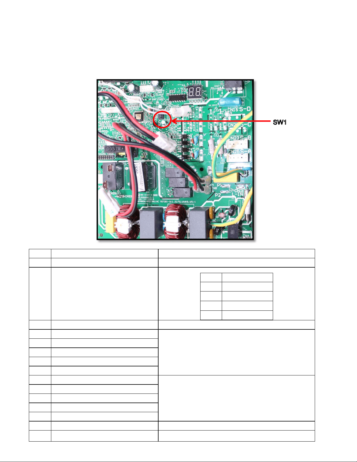
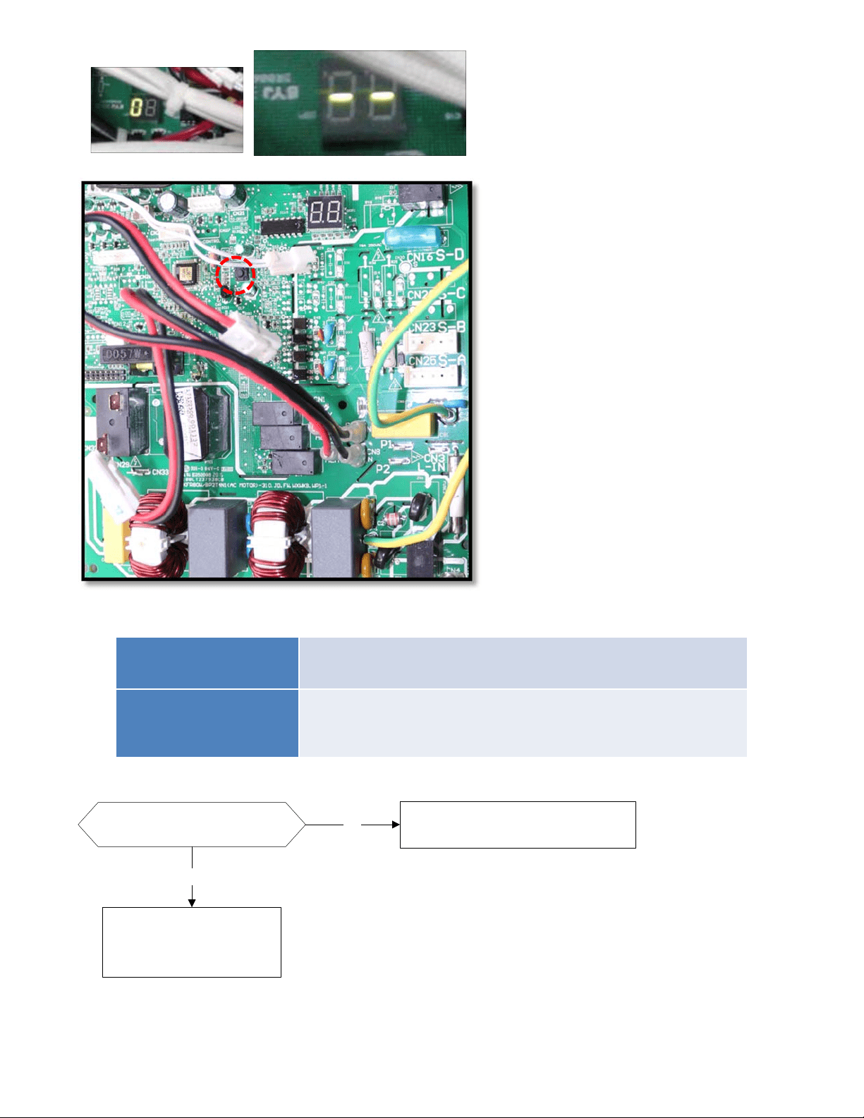
8.3 Outdoor Unit Display
8.3.1 Outdoor unit point check function:
There is a pushbutton switch in the outdoor PCB as marked below (SW1).
Push the switch SW1 to check the states of unit when it is running. The digital display LED will display
the following information after pushing the SW1 each time. See below table indicating the information
displayed for the number sequence of presses of the button.
Display Remark
0 Normal display
Display running frequency, running state or malfunction code
1 Quantity of indoor units in good connection Actual data
Display Number of indoor unit
1 1
2 2
3 3
4 4
2 Outdoor unit running mode code Off:0,Fan only 1, Cooling:2, Heating:3, Forced cooling:4
3 A indoor unit capacity
The capacity unit is horse power. If the indoor unit is not connected, the
digital display tube will show: “――”
(9K:1HP,12K:1.2HP,18K:1.5HP)
4 B indoor unit capacity
5 C indoor unit capacity
6 D indoor unit capacity
7 E indoor unit capacity
8 A Indoor unit capacity demand code
Norm code*HP
(9K:1HP,12K:1.2HP,18K:1.5HP)
9 B Indoor unit capacity demand code
10 C Indoor unit capacity demand code
11 D Indoor unit capacity demand code
12 E Indoor unit capacity demand code
13 Outdoor unit amendatory capacity demand code
Forced cooling:7
14 The frequency corresponding to the total indoor
units amendatory capacity demand
15 The frequency after the frequency limit
16 The frequency sending to compressor control
chip
17 A indoor unit evaporator outlet temp.(T
2B
A)
If the temp. is lower than -9 degree, the digital display tube will show “-
9”.If the temp. is higher than 70 degree, the digital display tube will show
“70”. If the indoor unit is not connected, the digital display tube will show:
“――”
18 B indoor unit evaporator outlet temp.(T
2B
B)
19 C indoor unit evaporator outlet temp.(T
2B
C)
20 D indoor unit evaporator outlet temp.(T
2B
D)
21 E indoor unit evaporator outlet temp.(T
2B
E)
22 A indoor unit room temp.(T
1
A) If the temp. is lower than 0 degree, the digital display tube will show “0”.If
the temp. is higher than 50 degree, the digital display tube will show
“50”. If the indoor unit is not connected, the digital display tube will show:
“――”
23 B indoor unit room temp.(T
1
B)
24 C indoor unit room temp.(T
1
C)
25 D indoor unit room temp.(T
1
D)
26 E indoor unit room temp.(T
1
E)
27 A indoor unit evaporator temp.(T
2
A)
If the temp. is lower than -9 degree, the digital display tube will show “-
9”.If the temp. is higher than 70 degree, the digital display tube will show
“70”. If the indoor unit is not connected, the digital display tube will show:
“――”
28 B indoor unit evaporator temp.(T
2
B)
29 C indoor unit evaporator temp.(T
2
C)
30 D indoor unit evaporator temp.(T
2
D)
31 E indoor unit evaporator temp.(T
2
E)
32 Condenser pipe temp.(T3)
33 Outdoor ambient temp.(T4)
34 Compressor discharge temp.(TP) The display value is between 30~129 degree. If the temp. is lower than
30 degree, the digital display tube will show “30”.If the temp. is higher
than 99 degree, the digital display tube will show single digit and tens
digit. For example, the digital display tube show “0.5”,it means the
compressor discharge temp. is 105 degree.)
35 AD value of current
The display value is hex number.
For example ,the digital display tube show “Cd”, it means AD value is
205.
36 AD value of voltage
37 EXV open angle for A indoor unit
Actual data/4.
If the value is higher than 99, the digital display tube will show single
digit and tens digit.
For example ,the digital display tube show “2.0”,it means the EXV open
angle is 120×4=480p.)
38 EXV open angle for B indoor unit
39 EXV open angle for C indoor unit
40 EXV open angle for D indoor unit
41 EXV open angle for E indoor unit
42 Frequency limit symbol
Bit7
Frequency limit caused by IGBT
radiator
The display
value is hex
number. For
example, the
digital display
tube show
2A,then Bit5=1,
Bit3=1, Bit1=1.
It means
frequency limit
caused by T4,T3
and current.
Bit6
Frequency limit caused by PFC
Bit5
Frequency limit caused by T4.
Bit4
Frequency limit caused by T2.
Bit3
Frequency limit caused by T3.
Bit2
Frequency limit caused by T5.
Bit1
Frequency limit caused by current
Bit0
Frequency limit caused by voltage
43 Average value of T2 (Sum T2 value of all indoor units)/( number of indoor units in good
connection)
44 Outdoor unit fan motor state Off:0, High speed:1, Med speed:2, Low speed:3 Breeze:4, Super
breeze:5
45 The last error or protection code 00 means no malfunction and protection
46 F indoor unit capacity
47 F Indoor unit capacity demand code
48 F indoor unit evaporator outlet temp.(T
2B
F)
49 F indoor unit room temp.(T
1
F)
50 F indoor unit evaporator temp.(T
2
F)
51 EXV open angle for F indoor unit

8.3.2 Outdoor unit’s digital display LED will display the following information except in the checking
mode as described above:
In standby , the LED displays “- -”
During the compressor is operating, the LED display the running frequency,
In defrosting mode, The LED displays “dF” or alternatively displays between running frequency
and “dF” (each displays 0.5s)
During compressor pre-heating, The LED displays “PH” or alternatively displays between
running frequency and “PH” (each displays 0.5s)
During the oil return process, The LED displays “RO” or alternatively displays between running
frequency and “RO” (each displays 0.5s)
In low ambient cooling mode, the LED displays “LC” or alternatively displays between running
frequency and “LC” (each displays 0.5s)
In forced cooling mode, the LED displays “FC” or alternatively displays between running
frequency and “FC”(each displays 0.5s)
When PFC module protection occurs three times within 15 minutes, the LED displays “E6” or
alternatively displays between running frequency and “E6” (each displays 0.5s)
In case of protection or malfunction, the LED displays error code or protection code.
8.3.3 Outdoor unit error display codes
Display LED STATUS New indoor Error
E0 Outdoor unit EEPROM parameter error
F4
E2 Communication malfunction between indoor and outdoor units
E1
E3
Communication malfunction between IPM board and outdoor main control
board
——
E4
Outdoor temperature sensor (coil sensor T3,ambient sensor T4, Compressor
discharge sensor T5、indoor coil outlet pipe sensor T2B) malfunction
F2/F1/F3/F6
E5 Over-voltage or under-voltage protection
P1
E6 PFC module protection
——
E8 Outdoor fan speed has been out of control
F5
F1 No. A Indoor unit coil outlet temp. sensor malfunction
——
F2 No. B Indoor unit coil outlet temp. sensor malfunction
——
F3 No. C Indoor unit coil outlet temp. sensor malfunction
——
F4 No. D Indoor unit coil outlet temp. sensor malfunction
——
F5 No. E Indoor unit coil outlet temp. sensor malfunction
——
F6 No. F Indoor unit coil outlet temp. sensor malfunction
——
P0 Compressor top high temperature protection (OLP)
P2
P1 High pressure protection
P2
P2 Low pressure protection
P2
P3 Current overload protection
F0
P4 Temperature protection of compressor discharge
——
P5 Condenser high temperature protection
——
P6 Inverter module (IPM) malfunction P0
8.4 Diagnosis and Solution
8.4.1 Indoor unit trouble shooting
8.4.1.1
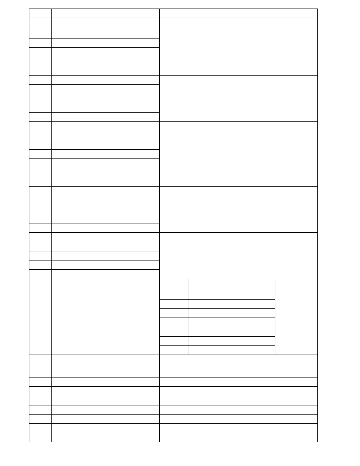
Indoor unit EEPROM parameter error diagnosis and solution.
Malfunction decision
conditions
PCB main chip does not receive feedback from EEPROM chip
● Installation mistake
● PCB faulty
Trouble shooting:
Supposed causes
EEPROM: aread‐onlymemorywhosecontentscanbeerasedandreprogrammedusingapulsedvoltage.
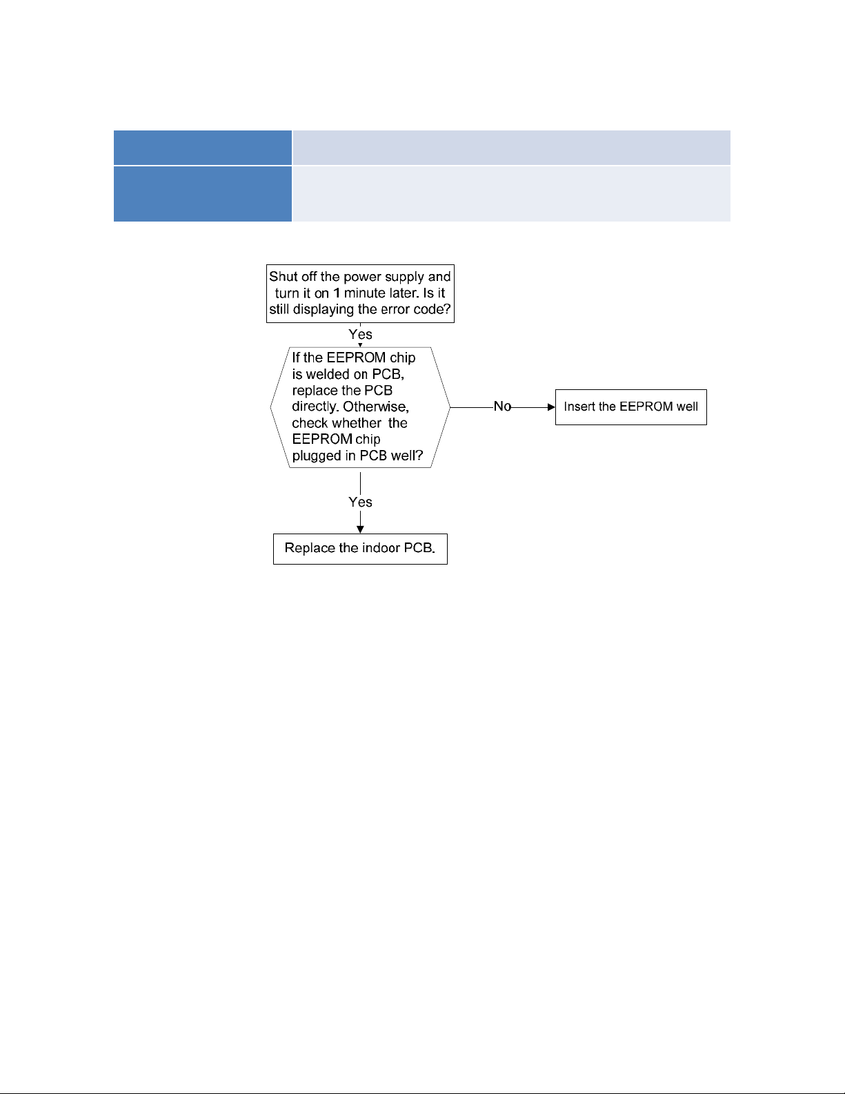
8.4.1.2 Communication malfunction between indoor and outdoor units diagnosis and
solution.
Malfunction decision
conditions
Indoor unit does not receive the feedback from outdoor unit
during 120 seconds.
Supposed causes
● Wiring mistake
● Indoor or outdoor PCB faulty
Trouble shooting:

Pic 1: Use a multimeter to test the
DC voltage between 2 (previously:
L2) port and S port of outdoor unit.
The red pin of multimeter connects
with 2 (previously: L2) port while
the black pin is for S port.
(Set multimeter to read DC volts)
When AC is normally running, the
voltage will move alternately
between positive value and
negative value.
Pic 1: Use a multimeter to test the
DC voltage between 2(old: L2) port
and S port of outdoor unit. The red
pin of multimeter connects with
2(old: L2) port while the black pin is
for S port.
When AC is normal running, the
voltage will move alternately
between positive value and
negative value.
Operating
Standby
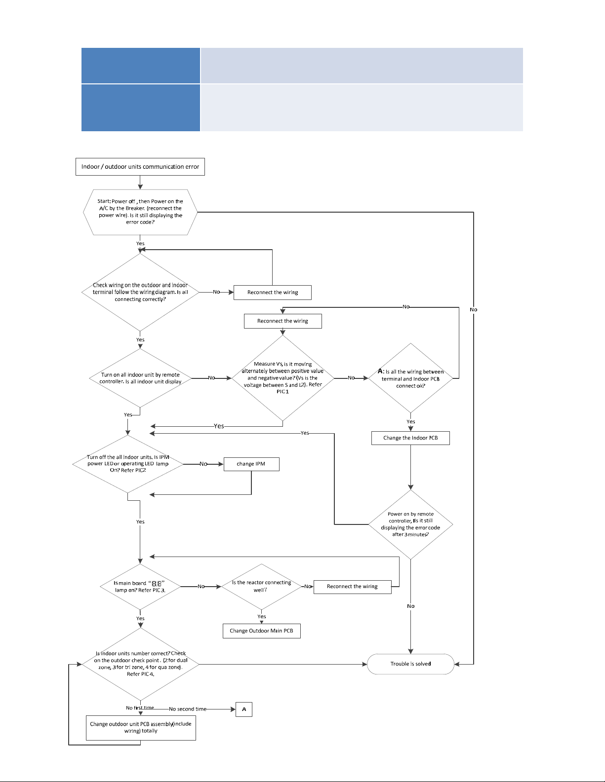
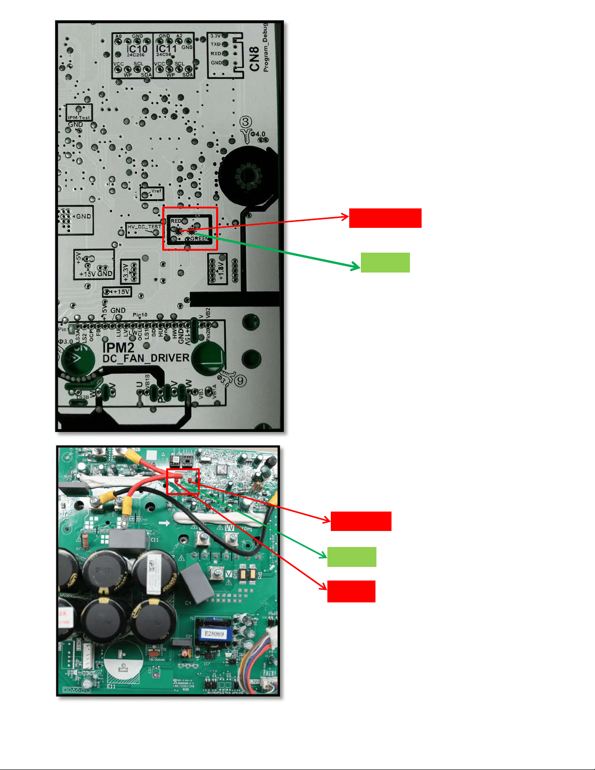
Pic 2: IPM (for5 zone)
Pic 2: IPM (for 2 zone/ 3-zone)
Power
Standby
Operating
8.4.1.3 Zero-crossing signal detection error diagnosis and solution.
Malfunction decision
conditions
When PCB does not receive zero crossing signal feedback for
4 minutes or the zero crossing signal time interval is abnormal.
Supposed causes
● Connection mistake
● PCB faulty
Trouble shooting:
Check if the connections and
power supply is normal ?
Correct the connections . Turn on the
unit when the power supply is good .
No
Yes
Indoor main PCB is
defective. Replace indoor
main PCB.
PIC4:Checkpointbutton,press1timeforcheck
howmanyindoorunitsareconnected.
PIC3:MainboardLEDwhenpoweronand
unitstandby.
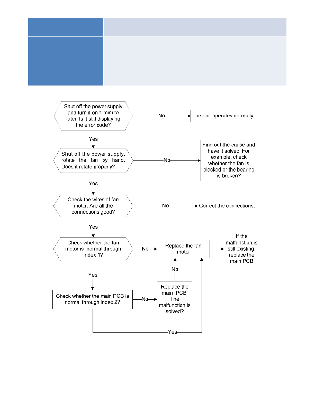
8.4.1.4 Indoor fan speed has been out of control diagnosis and solution.
Malfunction decision
conditions
When indoor fan speed keeps too low (300RPM) for certain time, the
unit will stop and the LED will display the failure.
Supposed causes
● Wiring mistake
● Fan ass’y faulty
● Fan motor faulty
● PCB faulty
Trouble shooting:
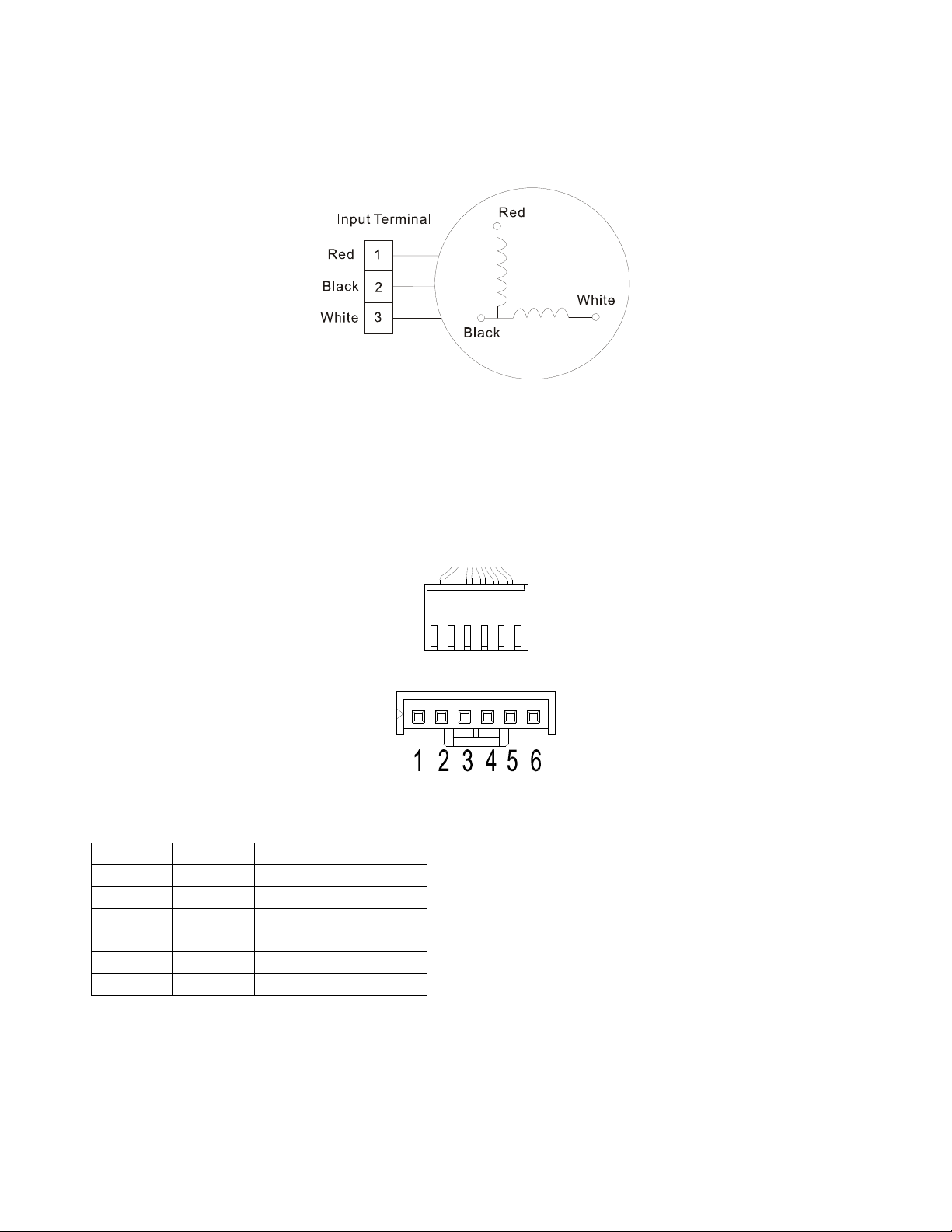
Index 1:
1: Indoor AC fan motor
Power on and set the unit running in fan mode at high fan speed. After running for 15 seconds,
measure the voltage of pin1 and pin2. If the value of the voltage is less than 100V (208~240V power
supply) or 50V(115V power supply), the PCB must have problems and need to be replaced.
2. Indoor DC fan motor (control chip is inside fan motor)
Power on and when the unit is in standby, measure the voltage of pin1-pin3, pin4-pin3 in fan motor
connector. If the value of the voltage is not in the range showing in below table, the PCB must have
problems and need to be replaced.
For other models:
DC motor voltage input and output
NO. Color Signal Voltage
1 Red Vs/Vm 200V~380V
2 --- --- ---
3 Black GND 0V
4 White Vcc 13.5-16.5V
5 Yellow Vsp 0~6.5V
6 Blue FG 13.5-16.5V
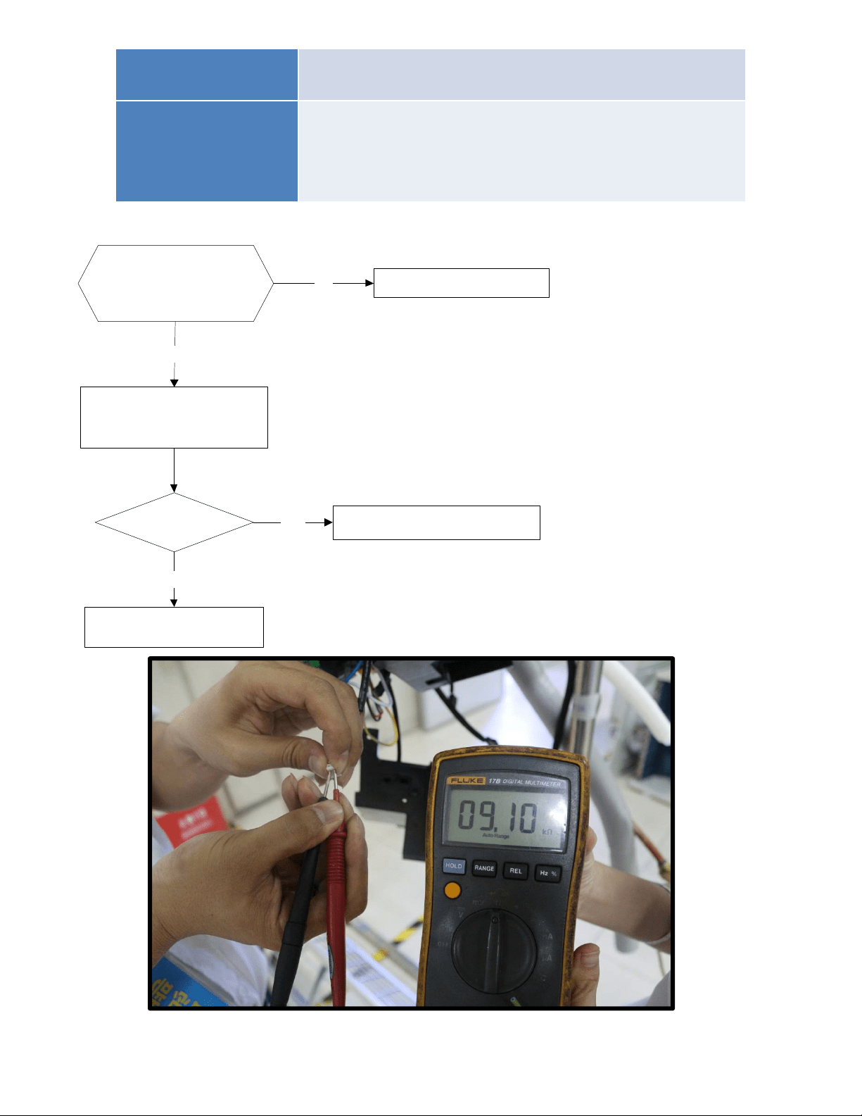
8.4.1.5 Temperature sensor malfunction diagnosis and solution.
Malfunction decision
conditions
If the sampling voltage is lower than 0.06V or higher than
4.94V, the LED will display the failure.
Supposed causes
● Wiring mistake
● Sensor faulty
● PCB faulty
Trouble shooting:
Check the connections
between temperature
sensor and PCB. Are
the connections good?
Correct the connections.No
Yes
Yes Replace indoor or outdoor PCB.
Replace the sensor
Check the resistance value
of the sensor via Appendix 1
and Appendix 2
Is it normal?
No
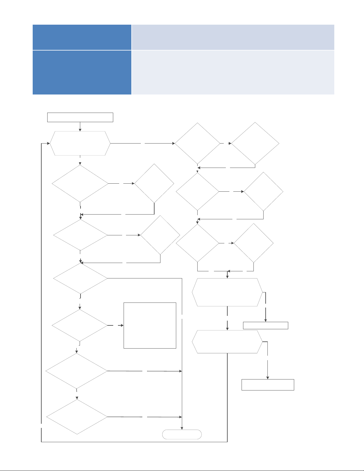
8.4.1.6 Inverter module (IPM) malfunction diagnosis and solution.
Malfunction decision
conditions
When the voltage signal that IPM send to compressor drive
chip is abnormal, the display LED will show “P6” and AC will
turn off.
Supposed causes
● Wiring mistake
● IPM malfunction
● Outdoor fan ass’y faulty
● Compressor malfunction
● Outdoor PCB faulty
Trouble shooting:
IPMmoduleprotection
Checkwhetherthevoltagerange
ofP‐NonIPMmoduleisnormal?
DC277‐356Vfor18‐27KBtu/h;
DC277‐410Vfor36K‐48KBtu/h
Yes
Yes
No
Yes
Checkwhethertheinput
powersupplyiscorrect?
208‐230V,1N,60Hz
No No
Regulateittocorrect,then
checkwhetherthesystem
canworknormally?
Checkwhetherthe
powersupplylineis
connectedcorrectlyand
tightly
Yes
Connectitcorrectly
andtightly,checkok
ornot?
No
Checkwhethertheconnecting
linebetweenmainboardand
theIPMmoduleisconnected
tightly
Yes
Connectittightly,
checkokornot?
No
No
No
Connectitwell,check
okornot?
Checkwhethertheconnecting
lineofthecompressoris
connectedcorrectlyortightly
ReplacetheIPMmodule,
checkwhetherthesystemcan
worknormally?
No
No
Replacethemainboard;check
whetherthesystemcanwork
normally?
No
Replacethecompressor,check
whetherthesystemcanwork
normally?
Checkwhetherthelines
inE‐partboxare
connectedtightly
Yes
Connectittightly,
checkokornot?
No
No
Yes
No
Replacethebridgerectifiers
Checkwhetherthebridgerectifiersare
normal?Usethemultimetertomeasure
theresistancebetweeneachtwo
terminals,checkwhetherthereisthe
conditionthatvalueofresistanceis0
Check whether the connecting line of
every reactor is normal? If the line is
broken,theresistanceofthetwoportsis
∞;Check whether the PFC module
broken.
Replacetheconnectinglineor
reactororreplacethePFCmodule
Yes
No
No
Yes
Troubleissolved
Checkiftheoutdoorfan
runsproperlyortheoutdoor
unitventilationisgood.
No
ForACfanmodels, pleaserefer
to9.4 TroubleCriterionOfMain
Parts,checkwhetherthe
resistanceofthefanmotoris
normal.Ifnot,replacethefan
motor.
ForDCfanmodels,referto
thesolutionoffanspeedhas
beenoutofcontrolmalfunction
.Findoutthecauseandhaveit
solved.
Yes
Yes
Yes
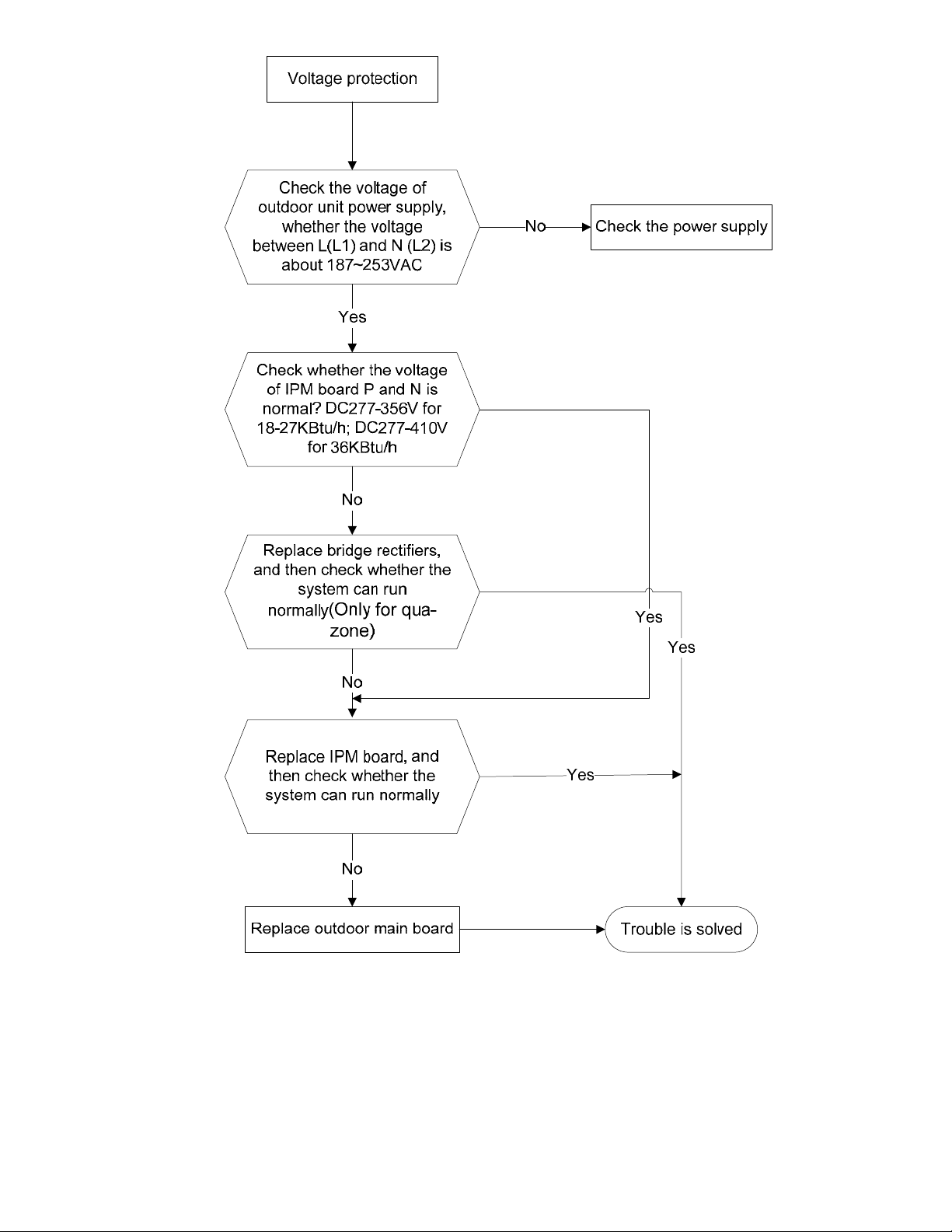
8.4.1.7 Over-voltage or under-voltage protection diagnosis and solution.
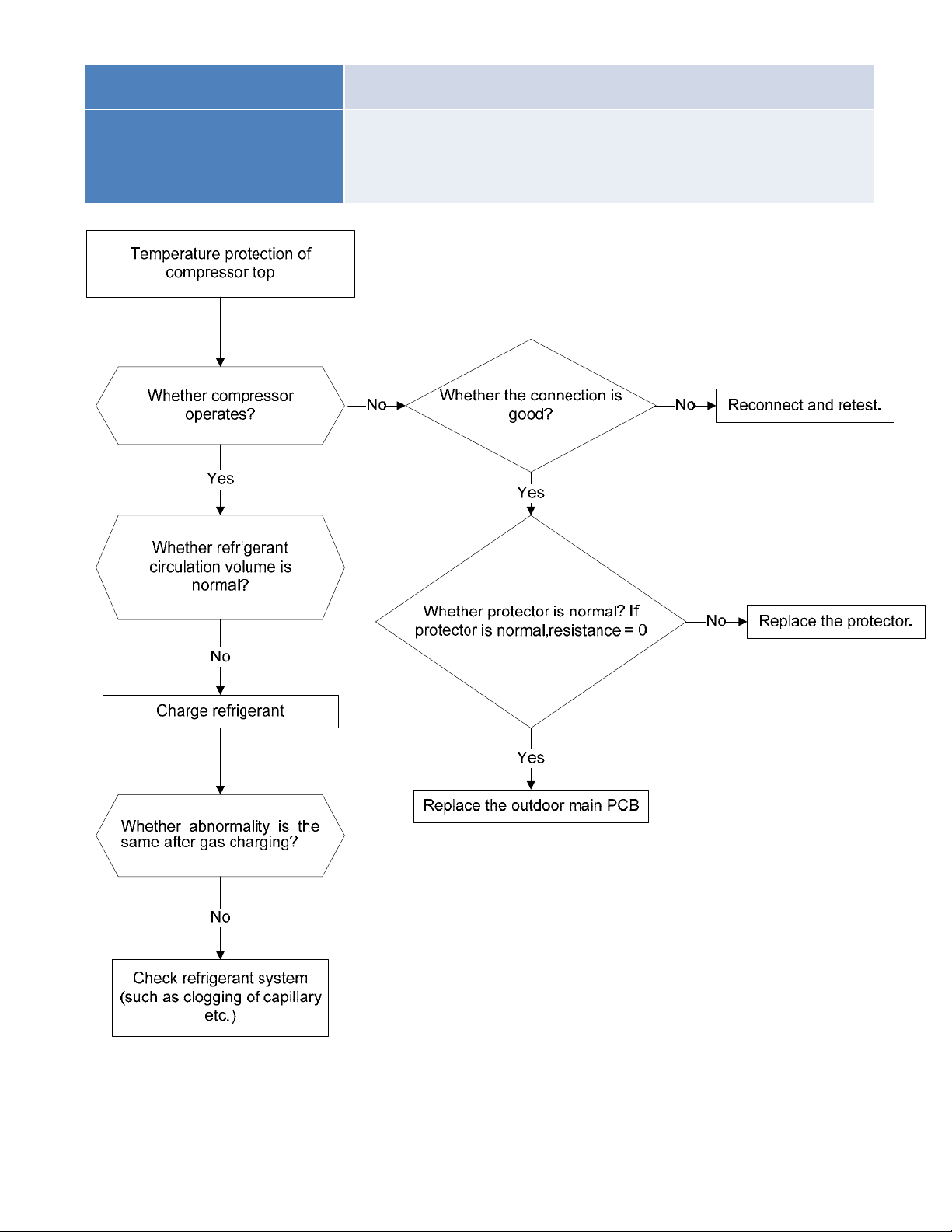
8.4.1.8 Compressor top high temperature protection (OLP) diagnosis and solution.
Malfunction decision
conditions
If the sampling voltage is not 5V, the LED will display the
failure.
Supposed causes
● Wiring mistake
● Over load protector faulty
● System block
● Outdoor PCB faulty
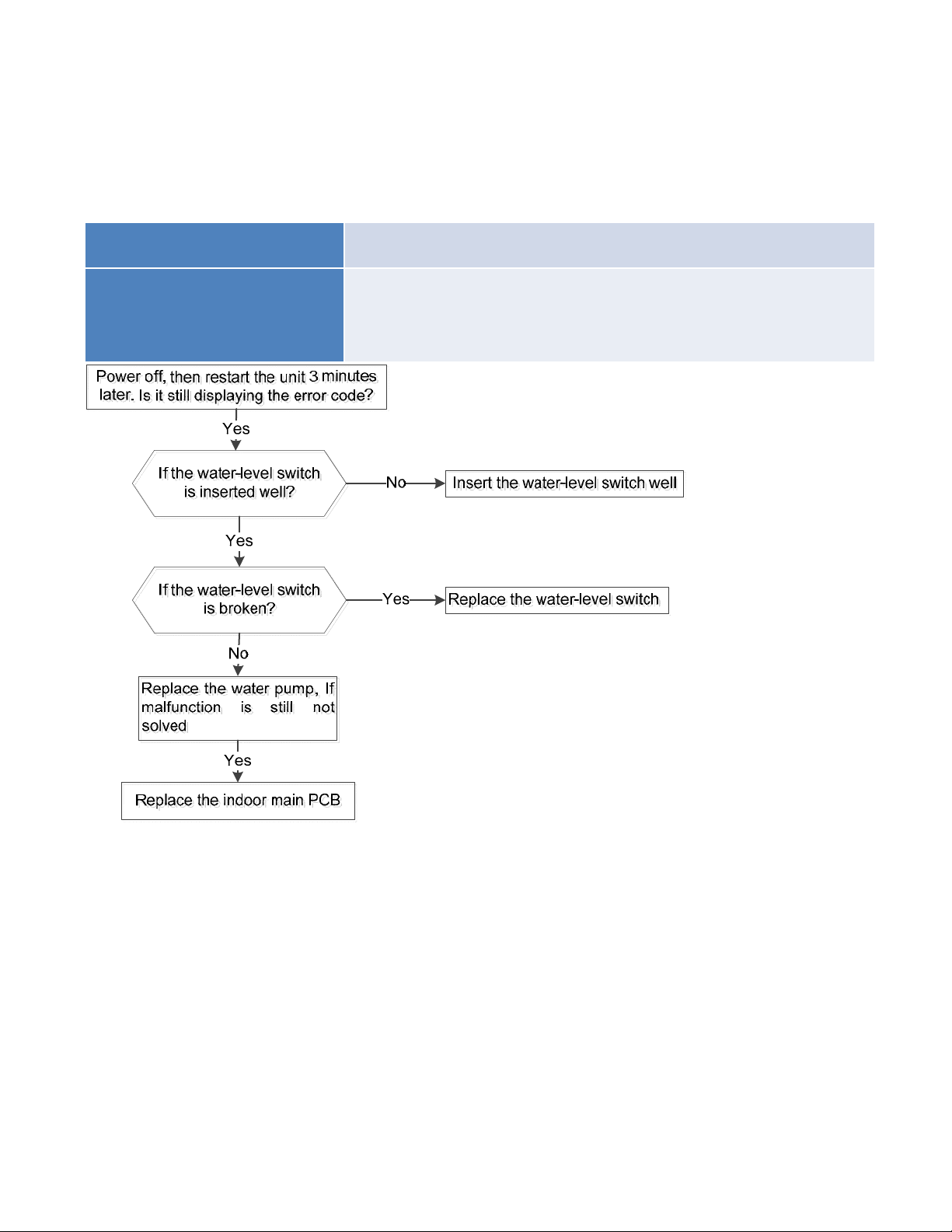
8.4.1.9 Compressor drive malfunction diagnosis and solution
The trouble shooting is same with one of IPM module protection(P0).
8.4.1.10
Water-level alarm malfunction diagnosis and solution
Malfunction decision
conditions
If the sampling voltage is not 5V, the LED will display the
failure.
Supposed causes
● Wiring mistake
● Water-level switch faulty
● Water pump faulty
● Indoor PCB faulty
8.4.1.11 Indoor unit mode conflict (Between indoor units).
Error Code P5
Malfunction decision
conditions
The indoor units cannot work cooling mode and heating at same time.
Heating mode has a priority.
Unit action
● Suppose Indoor unit A working in cooling mode or fan mode, and
indoor unit B is set to heating mode, then A will change to off and
B will work in heating mode.
● Suppose Indoor unit A working in heating mode, and indoor unit
B is set to cooling mode or fan mode, then B will change to stand
by and A will be no change.
Cooling mode Heating Mode Fan Off
Cooling mode No Yes No No
Heating Mode Yes No Yes No
Fan No Yes No No
Off No No No No
No: No mode conflict;
Yes: Mode conflict
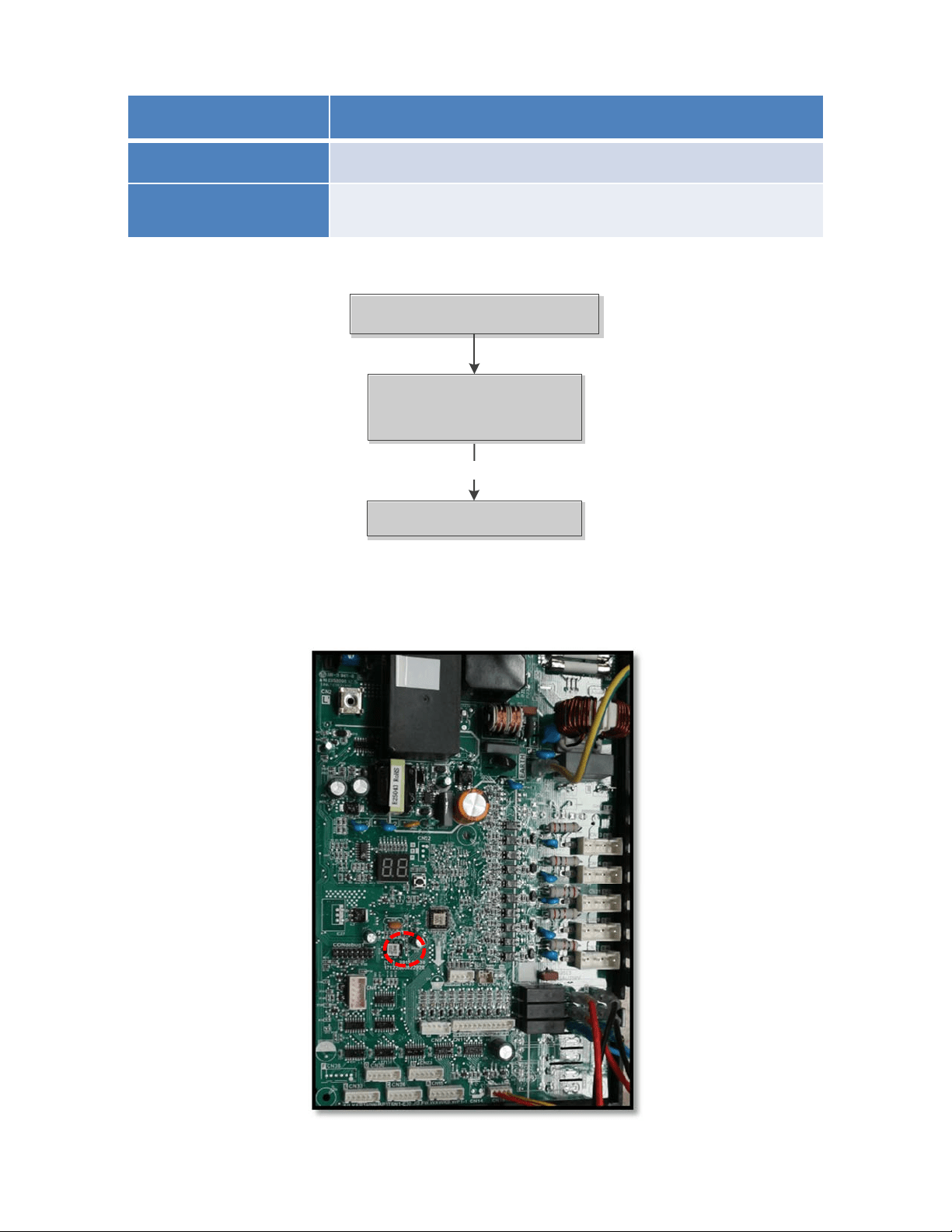
8.4.2 Outdoor unit trouble shooting
8.4.2.1 E0 (Outdoor unit EEPROM parameter error) diagnosis and solution
Error Code E0
Malfunction decision
conditions
PCB main chip does not receive feedback from EEPROM chip
Supposed causes
● Installation mistake
● PCB faulty
Trouble shooting:
Yes
Replace the outdoor main
PCB
Replace the outdoor main
PCB
Power off, then restart the
unit 3 minutes later
Power off, then restart the
unit 3 minutes later
Outdoor EEPROM malfunction
Outdoor EEPROM malfunction
EEPROM: aread‐onlymemorywhosecontentscanbeerasedandreprogrammedusingapulsedvoltage.For
thelocationofEEPROMchip,pleaserefertothebelowphotos.
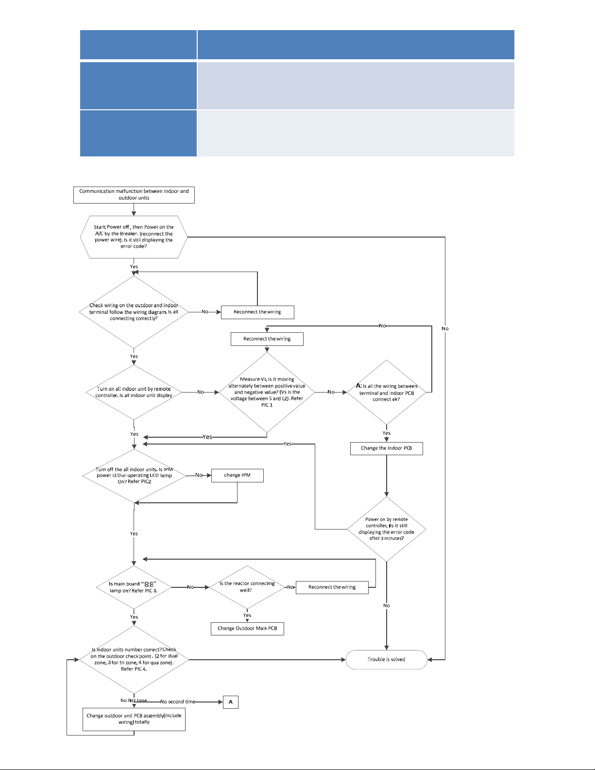
8.4.2.2 E2(Communication malfunction between indoor and outdoor units) diagnosis and solution.
Error Code E2
Malfunction decision
conditions
Indoor unit does not receive the feedback from outdoor unit
during 120 seconds or outdoor unit does not receive the
feedback from any one indoor unit during 180 seconds.
Supposed causes
● Wiring mistake
● Indoor or outdoor PCB faulty
Trouble shooting:
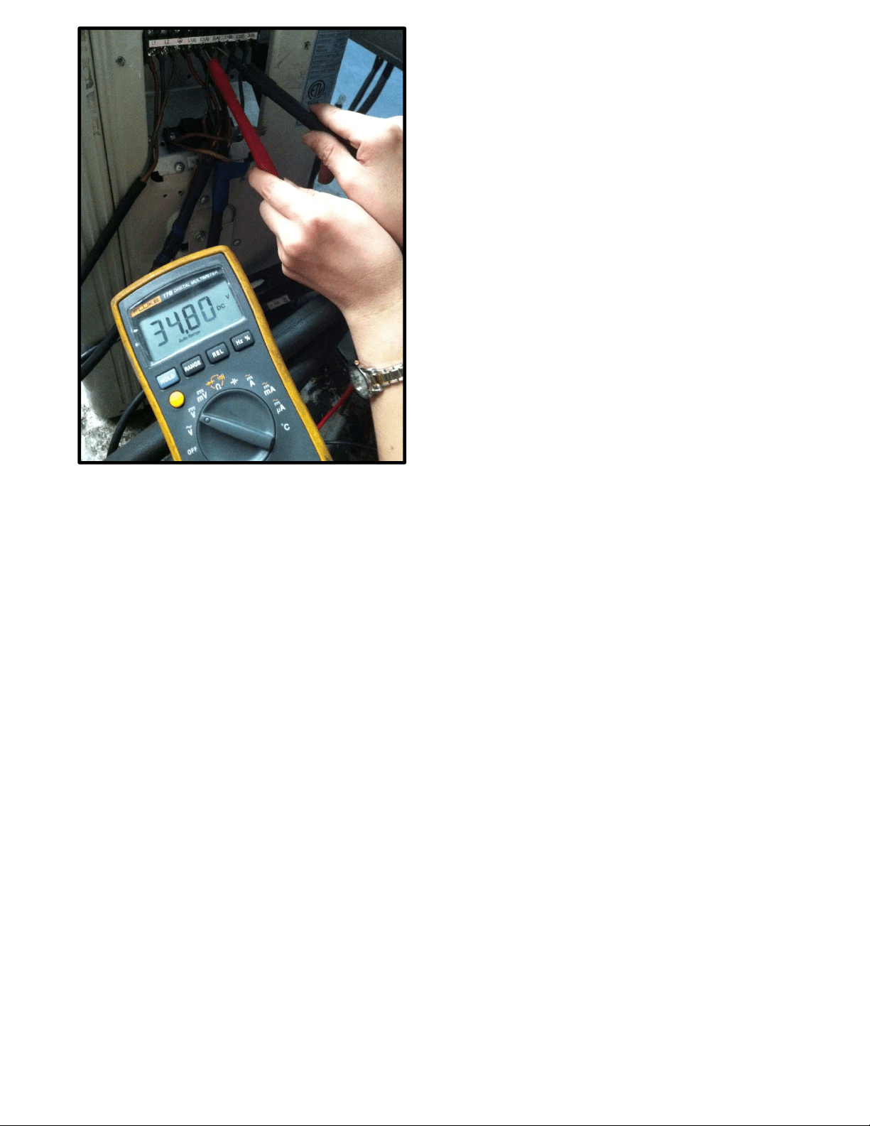
Pic 1: Use a multimeter to test the
DC voltage between 2 (previously:
L2) port and S port of outdoor unit.
The red pin of multimeter connects
with 2 (previously: L2) port while
the black pin is for S port.
(Set the multimeter to read DC volts
When AC is normal running, the
voltage will move alternately
between positive value and
negative value.

Operating
Standby
Pic 2: IPM (for5 zone)
Pic 2: IPM board (for 2 zone/ 3-zone)
Power
Standby
Operating
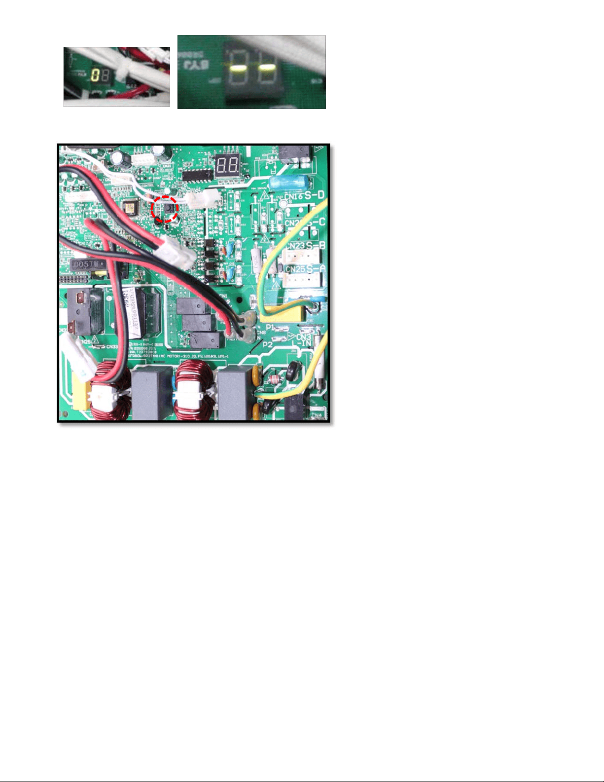
PIC4:Checkpointbutton,press1timeforcheck
howmanyindoorunitsareconnected.
PIC3:MainboardLEDwhenpoweronand
unitstandby.
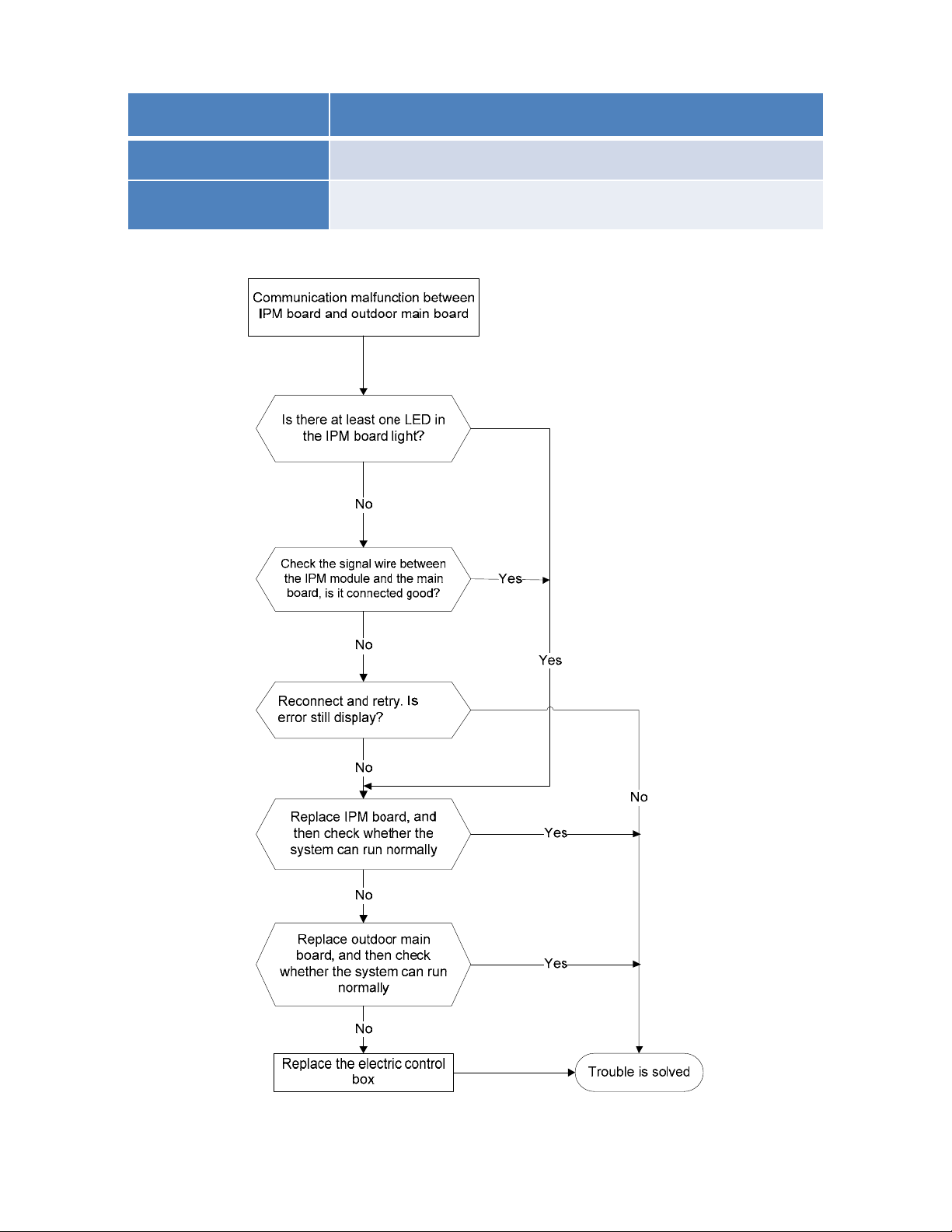
8.4.2.3 E3 (Communication malfunction between IPM board and outdoor main control board)
diagnosis
Error Code E3
Malfunction decision
conditions
PCB main chip does not receive feedback from IPM module
durin
g
60 seconds.
Supposed causes
● Wiring mistake
● PCB faulty
Trouble shooting:
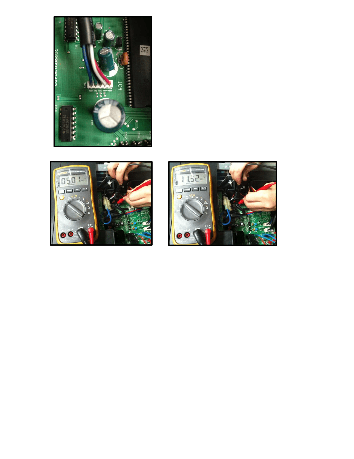
Remark:
Use a multimeter to test the DC
voltage between black pin and
white pin of signal wire The normal
value should be around 5V.
Use a multimeter to test the DC
voltage between black pin and red
pin of signal wire. The normal value
should be around 12V.

8.4.2.4 E4 (Outdoor temperature sensor (coil sensor T3,ambient sensor T4, Compressor discharge
sensor T5、indoor coil outlet pipe sensor T2B) malfunction) diagnosis and solution
F1/F2/F3/F4/F5 (No.A,B,C,D,E Indoor unit coil outlet temp. sensor malfunction) diagnosis and
solution.
.
Error Code E4/F1/F2/F3/F4/F5
Malfunction decision
conditions
If the sampling voltage is lower than 0.06V or higher than
4.94V, the LED will display the failure.
Supposed causes
● Wiring mistake
● Sensor faulty
● PCB faulty
Trouble shooting:
Check the connections
between temperature
sensor and PCB. Are
the connections good?
Correct the connections.No
Yes
Yes Replace indoor or outdoor PCB.
Replace the sensor
Check the resistance value
of the sensor via Appendix 1
and Appendix 2
Is it normal?
No
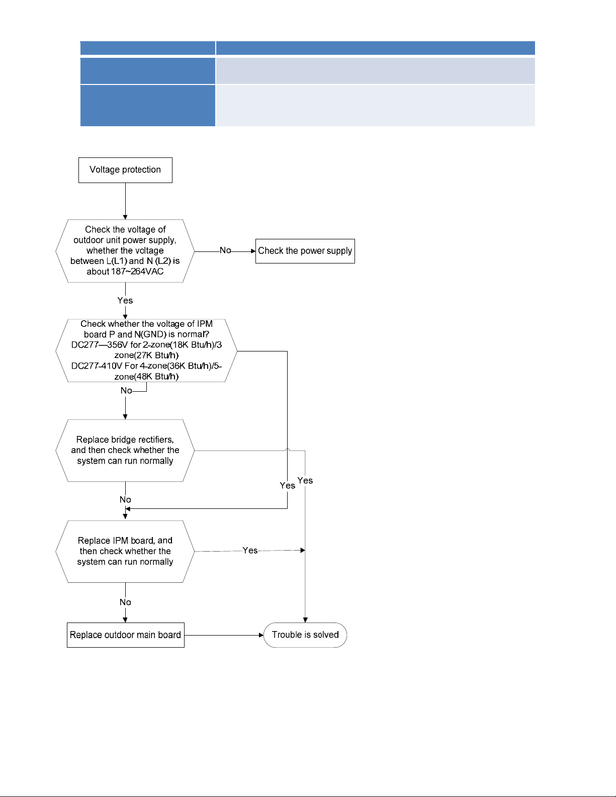
8.4.2.5 E5 (Over-voltage or under-voltage protection) diagnosis and solution.
Error Code E5
Malfunction decision
conditions
An abnormal voltage rise or drop is detected by checking the
specified voltage detection circuit.
Supposed causes
● Power supply problems.
● System leakage or block
● PCB faulty
Trouble shooting:
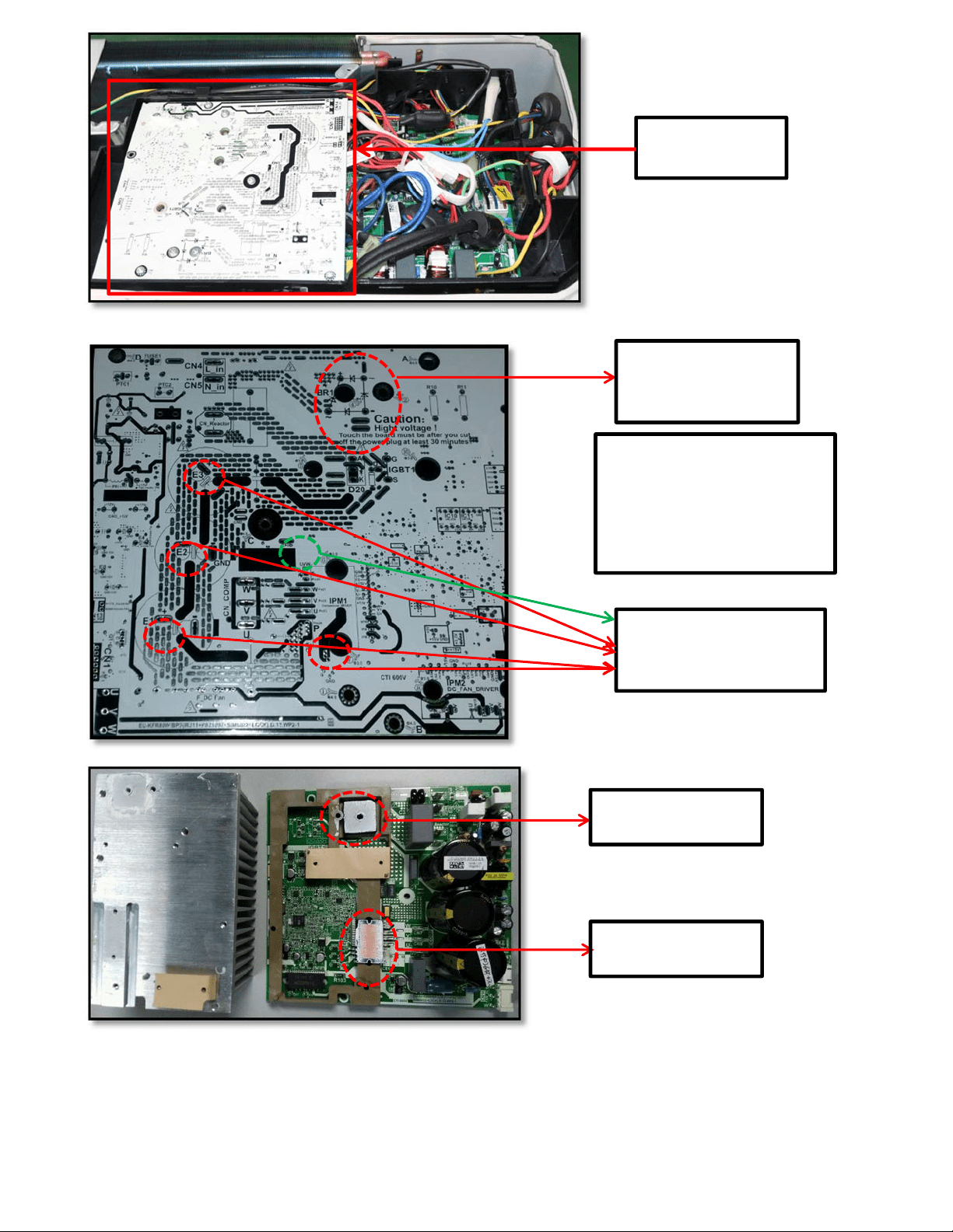
IPM board (for
2-zone /3-zone)
P(or E1/E2/E3)-N(GND)
(for 2-zone/3-zone)
Bridge rectifier
(for 2-zone/3-zone)
Bridge rectifier
(
for 2-zone/3-zone
)
IPM Module
(
for 2-zone/3-zone
)
Remark:
Measure the DC voltage
between + and - port. The
normal value should be
190V~250V.
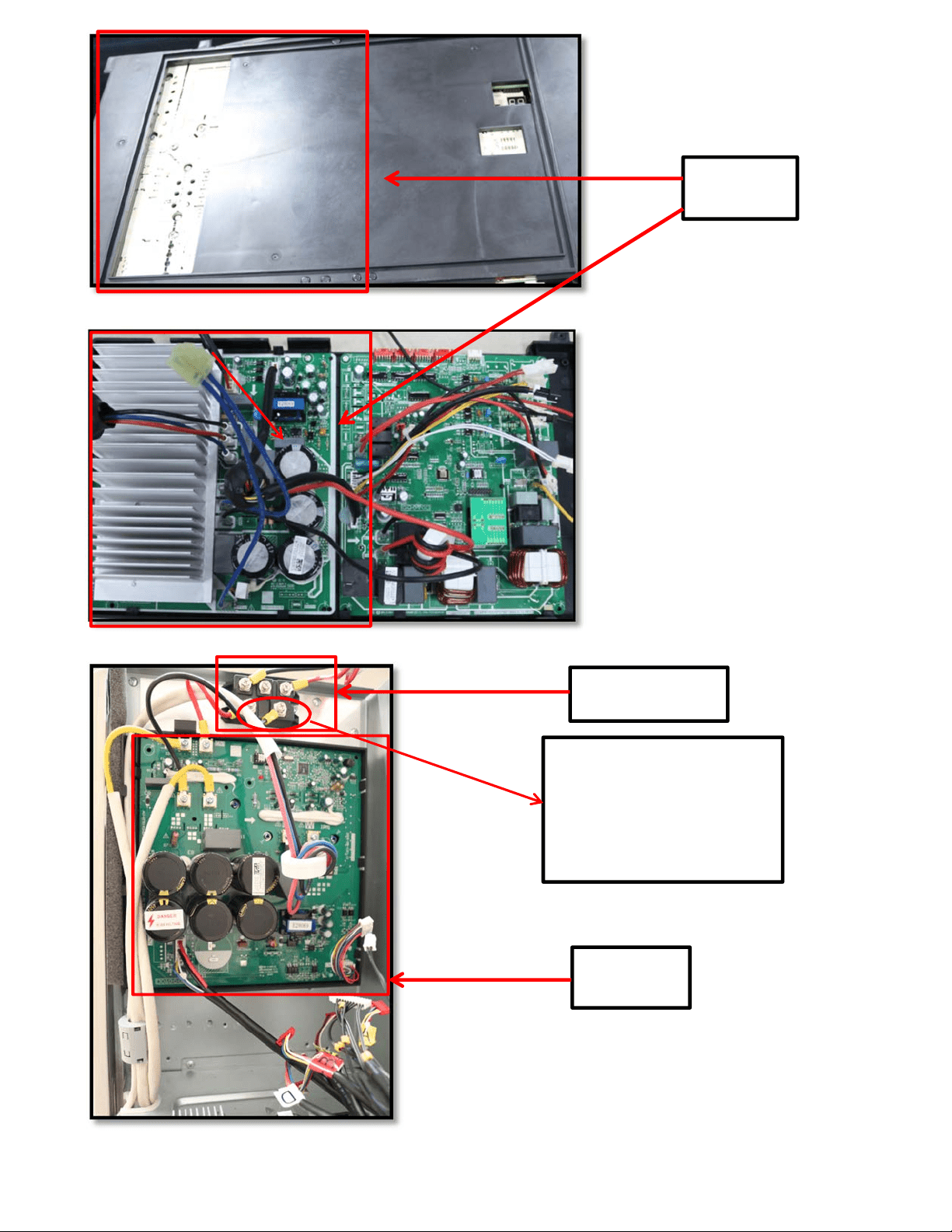
IPM board
(for 4-zone)
IPM board
(for 5-zone)
Bridge rectifier
(
f
or 5-zone
)
Remark:
Measure the DC voltage
between + and - port. The
normal value should be
190V~250V.
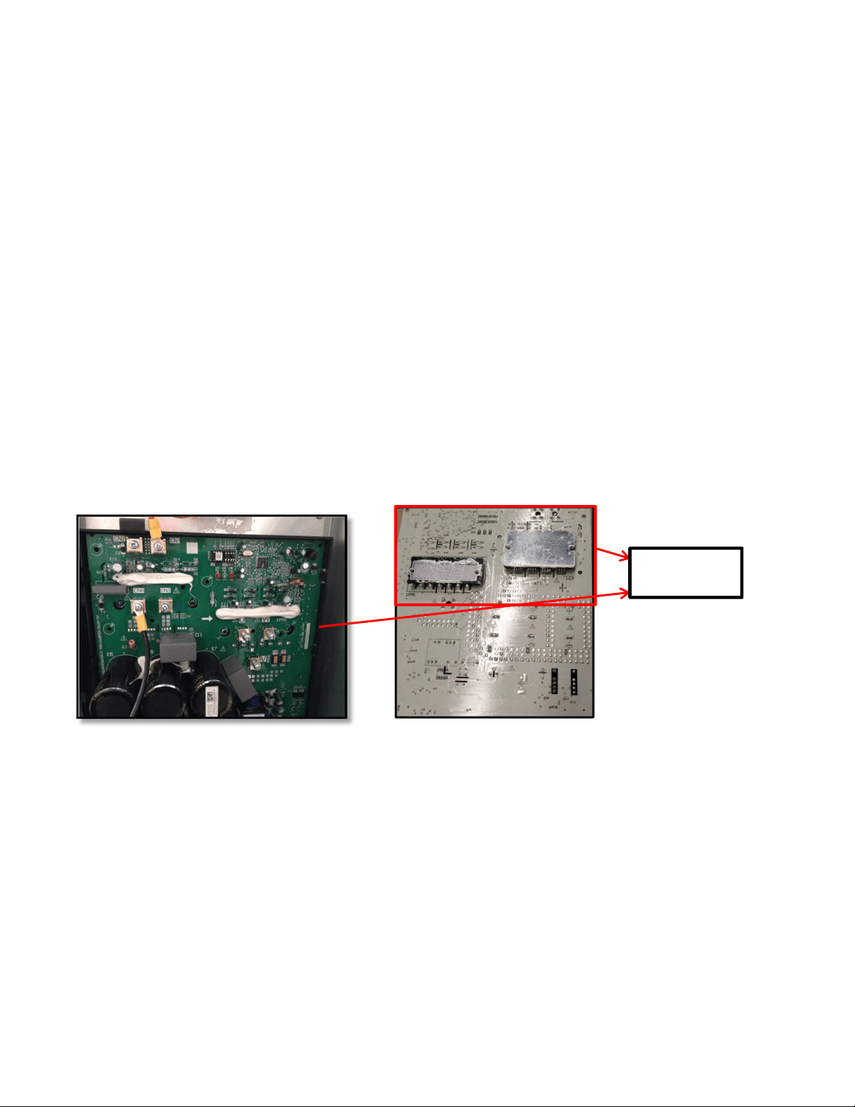
IPM Module
(
for 5-zone
)
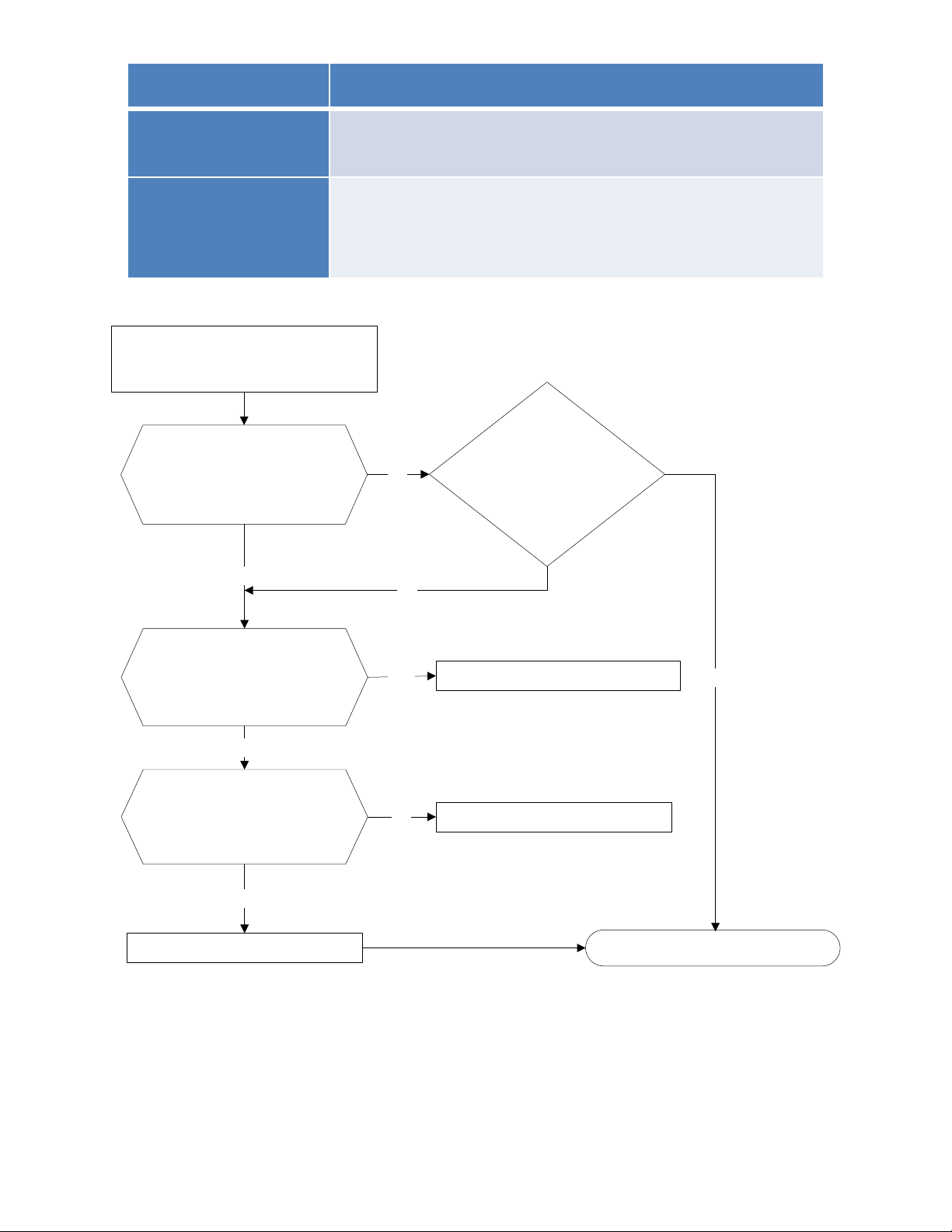
8.4.2.6 E6 (PFC module protection) error diagnosis and solution.
Error Code E6
Malfunction decision
conditions
When the voltage signal that PFC sends to main control board
is abnormal, the display LED will show “E6” and AC will turn
off.
Supposed causes
● Wiring mistake
● Outdoor PCB faulty
● Inductance of PFC module faulty
● PFC module malfunction
Trouble shooting:
PFC module protection
Check whether the
connecting line between
main board and the PFC
module is connected tightly
Yes
Check whether the voltage
range of P-N on IPM
module is normal? DC277-
356V for 18-27KBtu/h;
DC277-410V for 36KBtu/h
No
Check whether the
inductance of PFC module
is good? If the inductance is
good, the resistance of the
two ports is 0
Yes
Replace the inductance
No
Connect it tightly, check
normal or not
Replace the outdoor main board
Yes
Yes
No
No
Replace the PFC module Trouble is solved
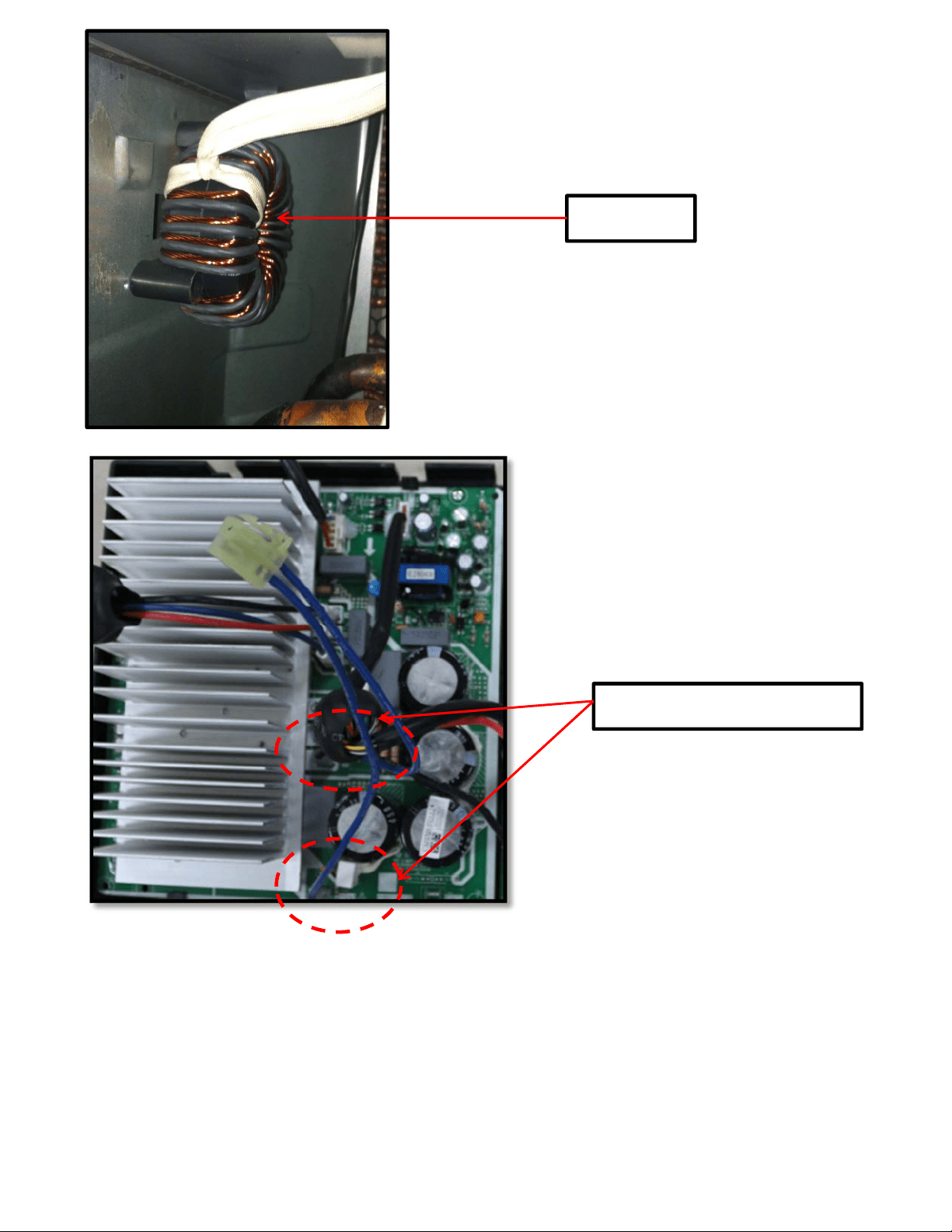
Two ports of the inductance
Inductance
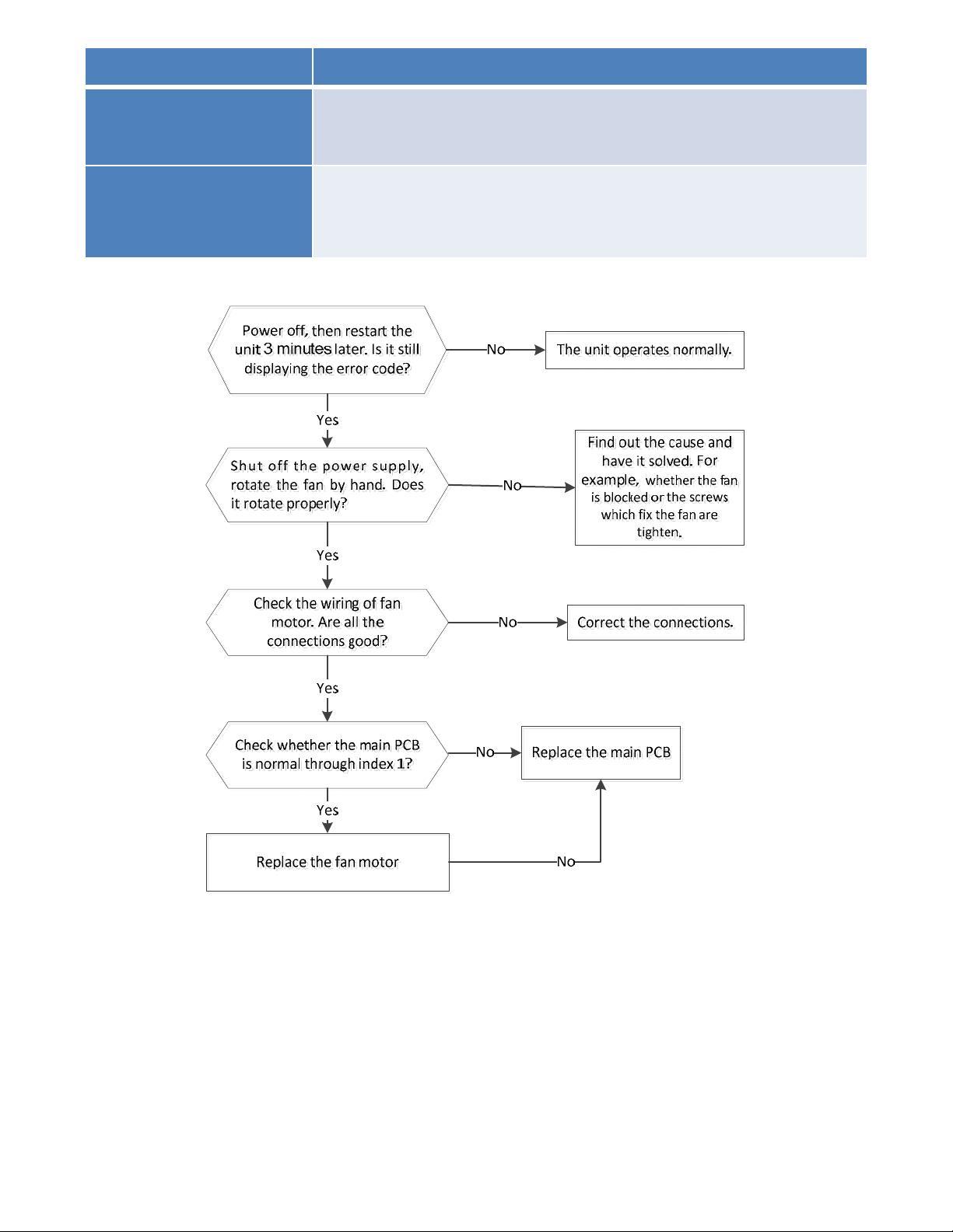
8.4.2.7 E8 (Outdoor fan speed has been out of control) diagnosis and solution
Error Code E8
Malfunction decision
conditions
When outdoor fan speed keeps too low (300RPM) or too
high(2400RPM) for certain time, the unit will stop and the LED will
display the failure.
Supposed causes
● Wiring mistake
● Fan ass’y faulty
● Fan motor faulty
● PCB faulty
Trouble shooting:
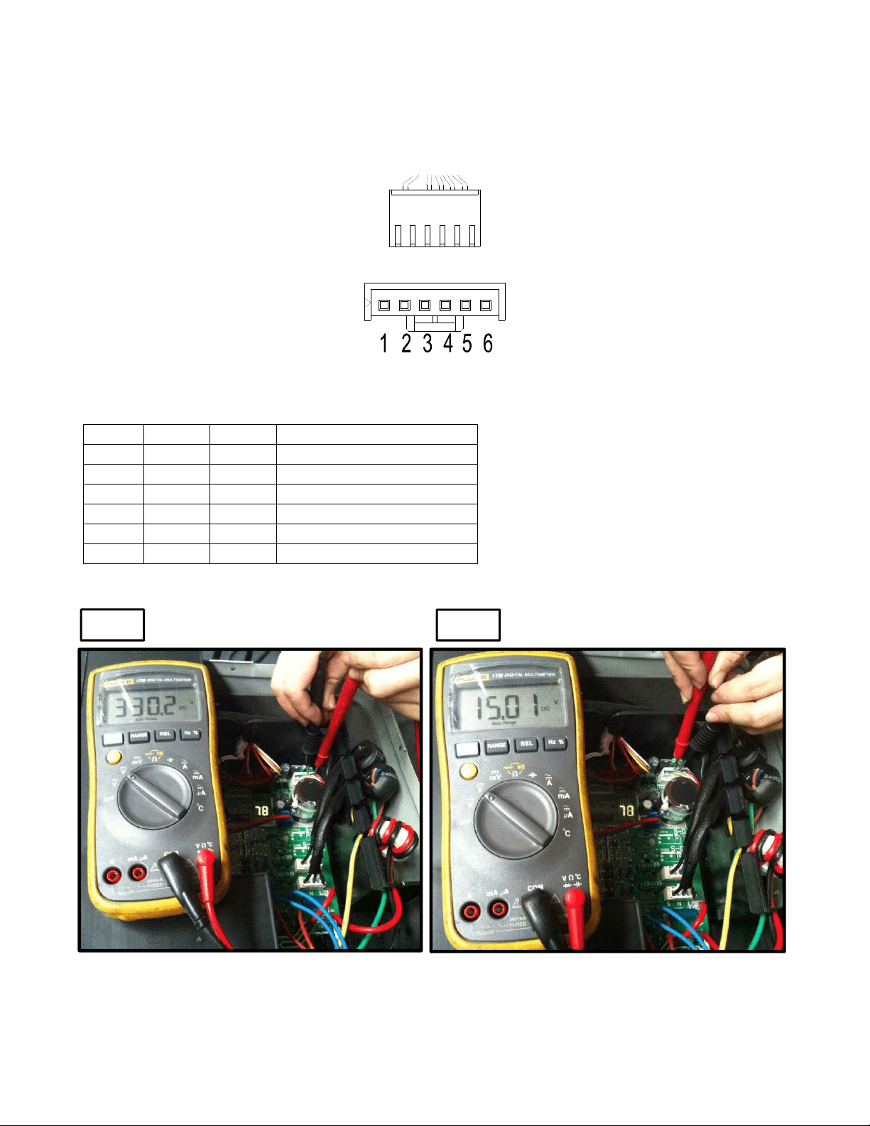
Index 1:
1. DC fan motor (control chip is inside fan motor)
Power on and when the unit is in standby, measure the voltage of pin1-pin3, pin4-pin3 in fan motor
connector. If the value of the voltage is not in the range showing in below table, the PCB must have
problems and need to be replaced.
DC motor voltage input and output
NO. Color Signal
V
oltage
1 Red Vs/Vm 200~380V
2 --- --- ---
3 Black GND 0V
4 White Vcc 13.5~16.5V
5 Yellow Vsp 0~6.5V
6 Blue FG 13.5~16.5V
Vs
Vcc
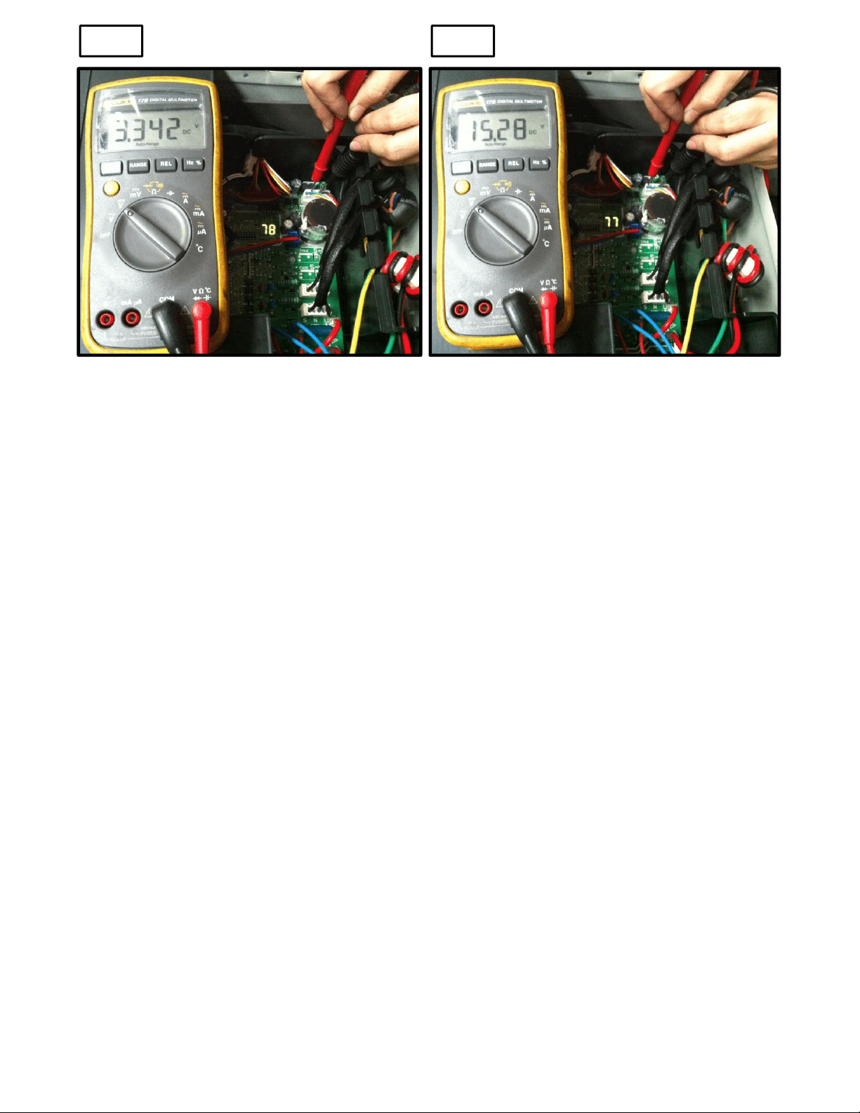
Vsp FG
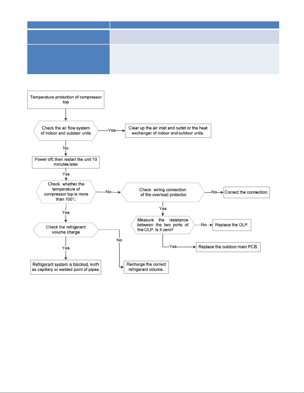
8.4.2.8 P0 (Compressor top high temperature protection (OLP)) diagnosis and solution.
Error Code P0
Malfunction decision
conditions
If the sampling voltage is not 5V, the LED will display the failure.
Supposed causes
● Wiring mistake
● Over load protector faulty
● System block
● Outdoor PCB faulty
Trouble shooting:
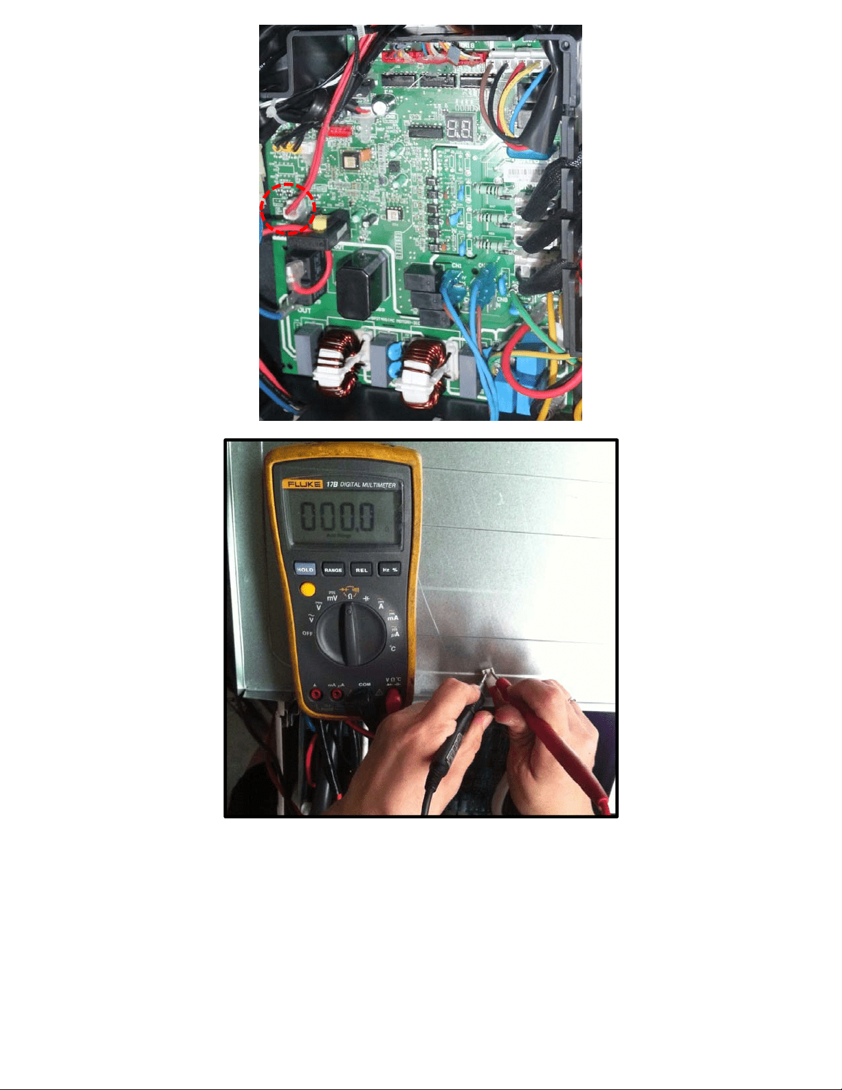

8.4.2.9 P1 (High pressure protection) diagnosis and solution.
Error Code P1
Malfunction decision
conditions
If the sampling voltage is not 5V, the LED will display the
failure.
Supposed causes
● Wiring mistake
● Over load protector faulty
● System block
● Outdoor PCB faulty
Trouble shooting:
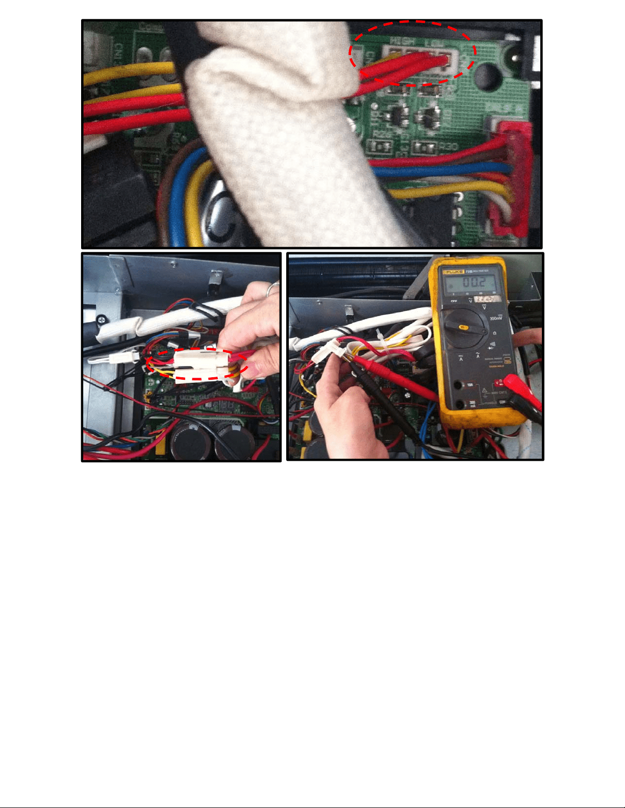
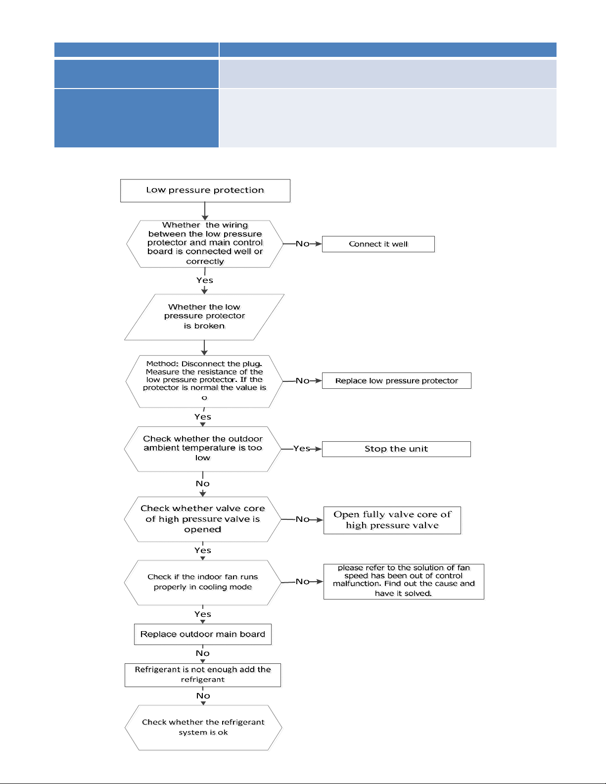
8.4.2.10 P2 (Low pressure protection) diagnosis and solution.
Error Code P2
Malfunction decision
conditions
If the sampling voltage is not 5V, the LED will display the
failure.
Supposed causes
● Wiring mistake
● Over load protector faulty
● System block
● Outdoor PCB faulty
Trouble shooting:
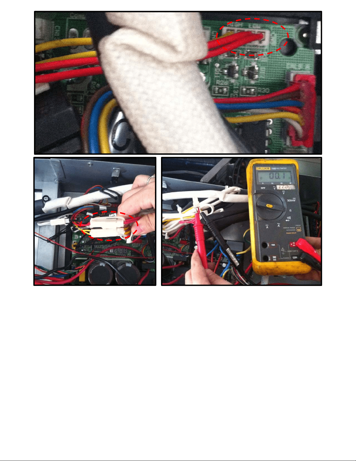
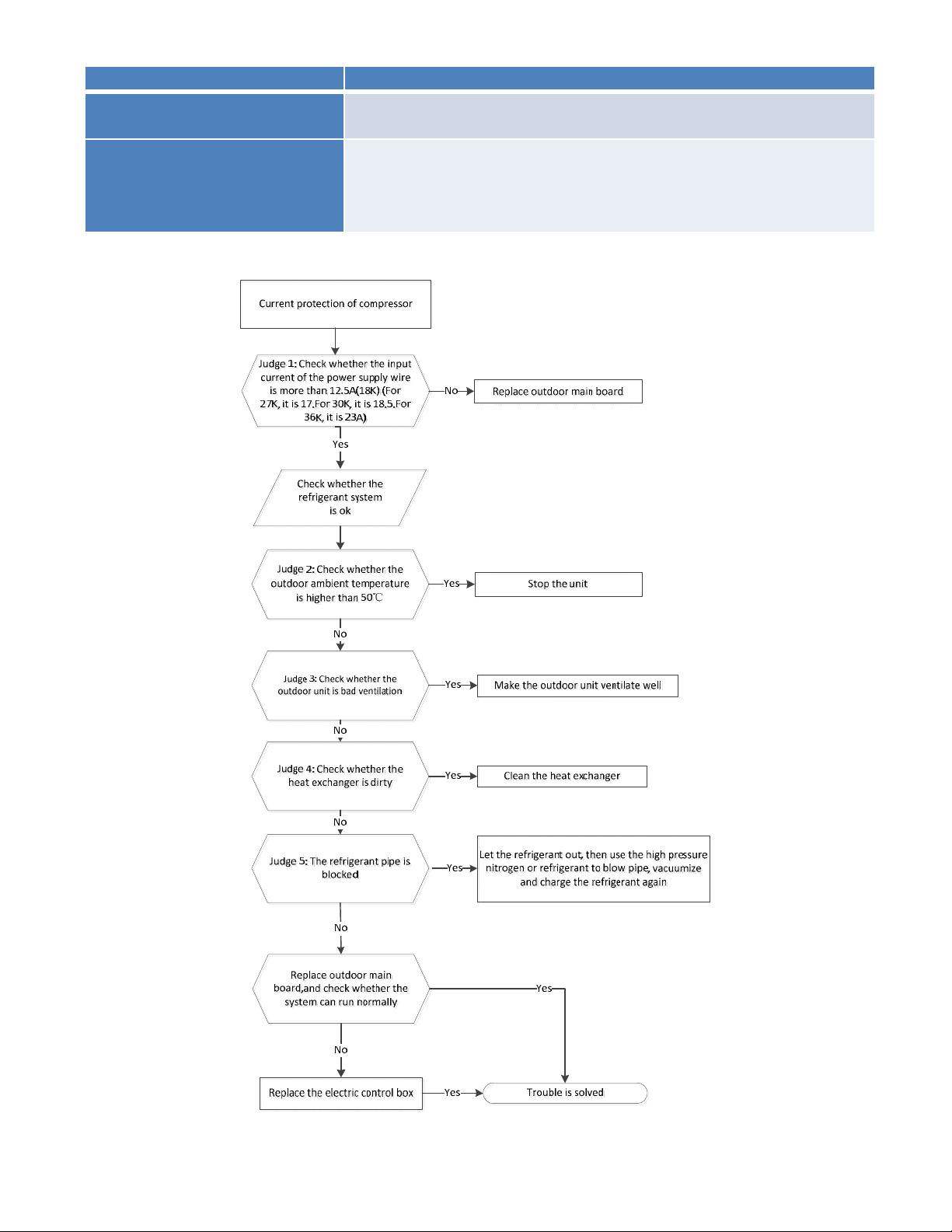
8.4.2.11 P3 (Current overload protection) diagnosis and solution.
Error Code P3
Malfunction decision
conditions
If the outdoor current exceeds the current limit value, the LED
will display the failure.
Supposed causes
● Wiring mistake
● Over load protector faulty
● System block
● Outdoor PCB faulty
Trouble shooting:
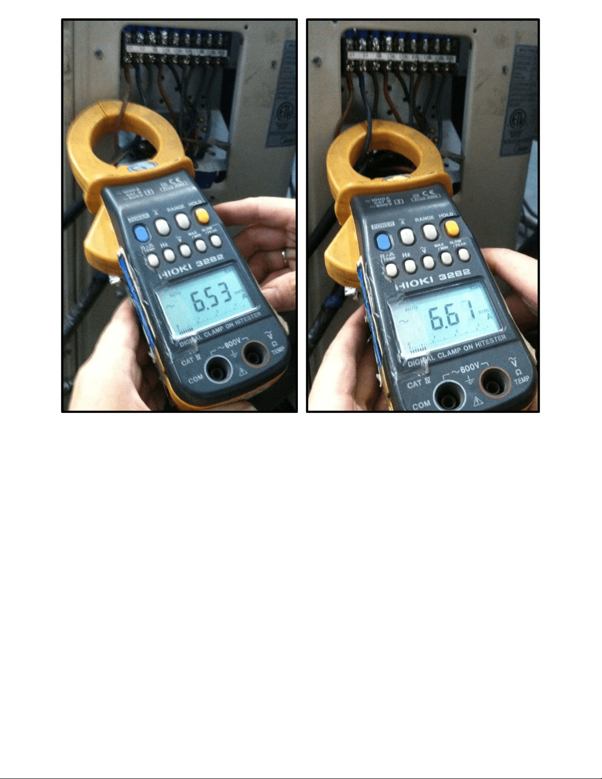
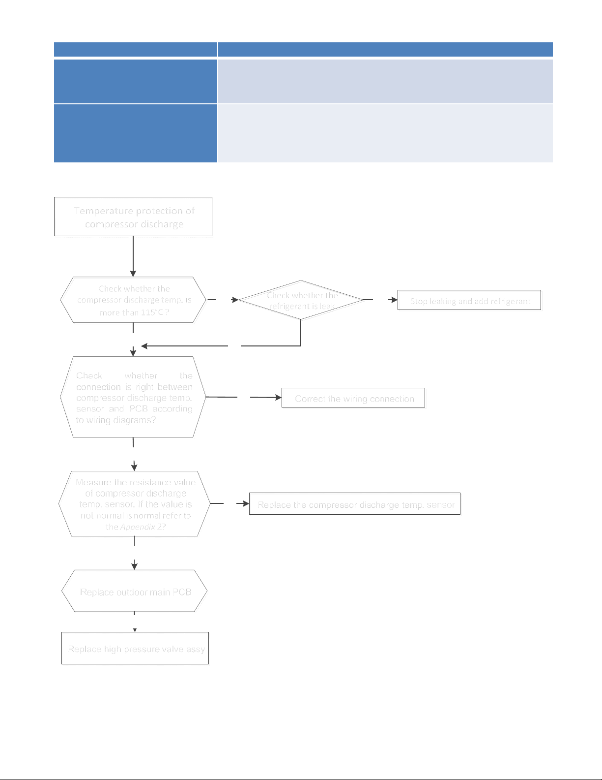
8.4.2.12 P4 (Temperature protection of compressor discharge) diagnosis and solution.
Error Code P4
Malfunction decision
conditions
When the compressor discharge temperature(T5) is more
than 115℃ for 10 seconds, the compressor will stop and
restart till T5 is less than 90℃.
Supposed causes
● Refrigerant leakage
● Wiring mistake
● The discharge temperature sensor faulty
● Outdoor PCB faulty
Trouble shooting:
Temperatureprotectionof
compressordischarge
Checkwhetherthe
compressordischargetemp.is
morethan115°C?
Check whether the
connection is right between
compressor discharge temp.
sensor and PCB according
to wiring diagrams?
Measure the resistance value
of compressor discharge
temp. sensor. If the value is
not normal isnormal referto
theAppendix 2?
No
Yes
Yes
No
Correct the wiring connection
Stopleakingandaddrefrigerant
Replace the compressor discharge temp. sensorNo
Yes
Replace high pressure valve assy
Yes
No
Replace outdoor main PCB
No
Checkwhetherthe
refrigerantisleak
8.4.2.13 P5 (High temperature protection of condenser) diagnosis and solution.
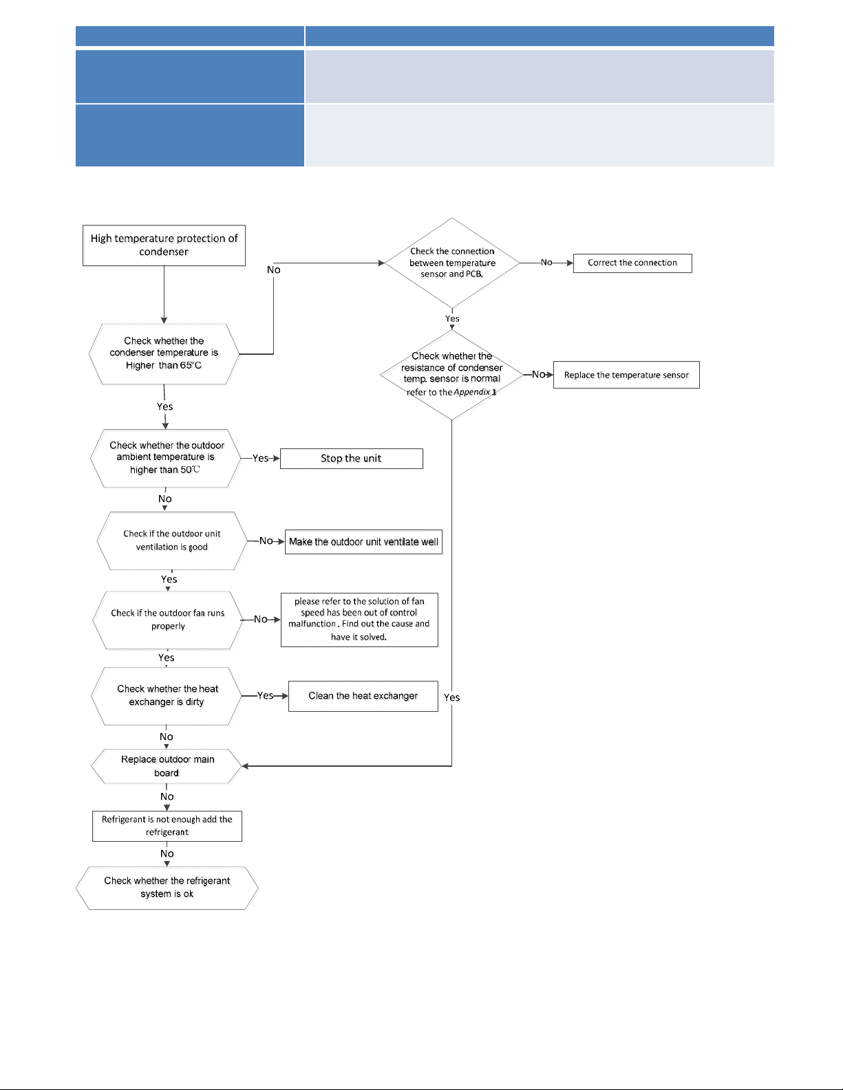
Error Code P5
Malfunction decision
conditions
When outdoor pipe temperature is more than 65°C, the unit will
stop, and unit runs again when outdoor pipe temperature is less
than 52°C
Supposed causes
● The condenser temperature sensor faulty
● Heat exchanger dirty
● System block
Trouble shooting:
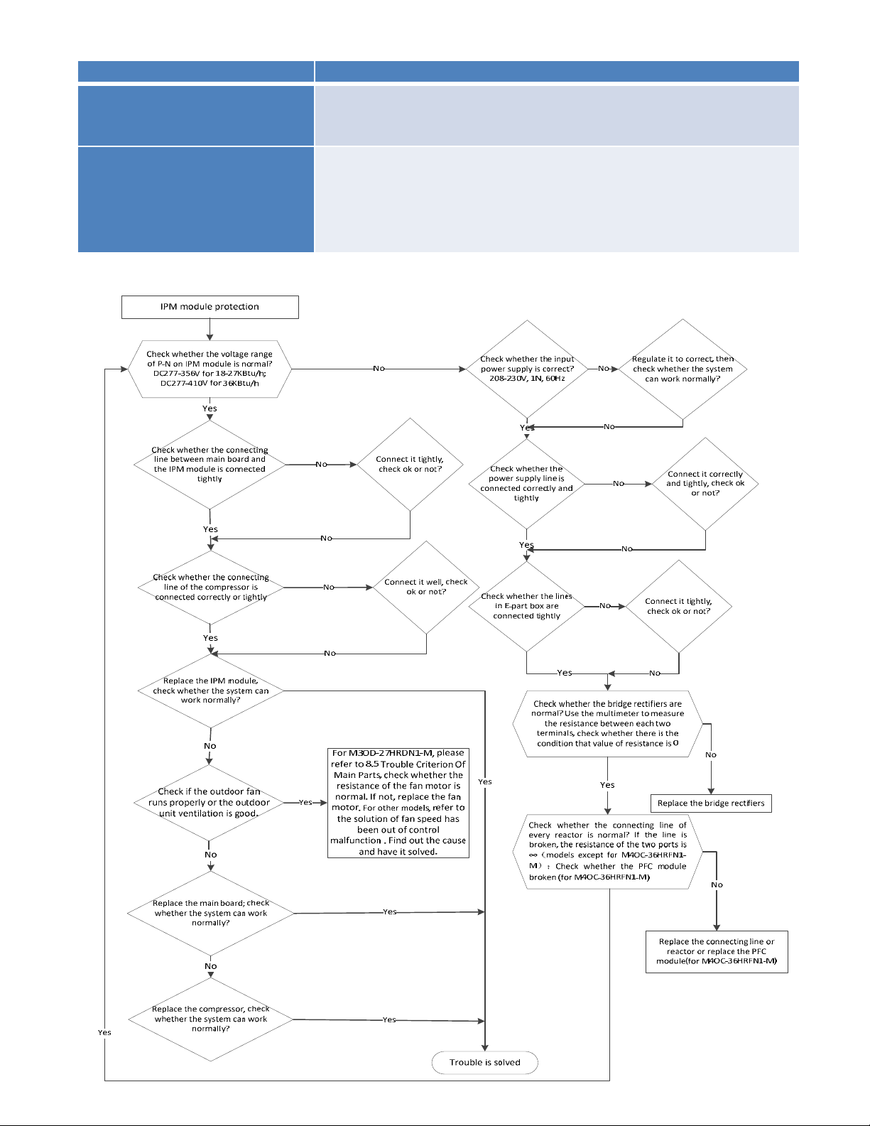
8.4.2.14 P6 (Inverter module (IPM) malfunction) diagnosis and solution.
Error Code P6
Malfunction decision
conditions
When the voltage signal that IPM send to compressor drive
chip is abnormal, the display LED will show “P6” and AC will
turn off.
Supposed causes
● Wiring mistake
● IPM malfunction
● Outdoor fan ass’y faulty
● Compressor malfunction
● Outdoor PCB faulty
Trouble shooting:
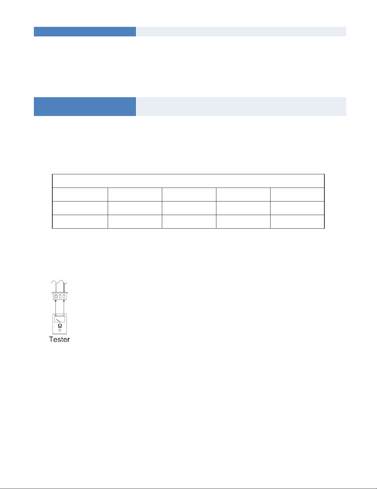
8.4.2.15 The cooling operation or heating operation does not operate.
Supposed causes
● 4-way valve faulty
Check of 4-way valve, please refer to part 5 in 9.5 Trouble Criterion of Main Parts.
8.4.2.16 When cooling, heat exchanger of non-operating indoor unit frosts.
When heating, non-operating indoor unit get warm.
Supposed causes
● EXV faulty
● Wire and tubing connected in reverse.
Check of EXV, please refer to part 6 in 9.5 Trouble Criterion of Main Parts.
8.5 Trouble Criterion of Main Parts.
Spec.
Outdoor unit
Model YN020GLFI22M2D YN030GLFI22M3D YN040GLFI22M4D YN050GLFI22M5D
Compressor
ATM150D23UFZ ATF235D22UMT ATF310D43UMT ATQ360D1UMU
Outdoor fan motor
ZKFN-50-8-2 ZKFN-120-8-2 ZKFN-120-8-2 ZKFN-85-8-22
Temperature sensor checking
Disconnect the temperature sensor from PCB, measure the resistance value with a tester.
Temperature Sensors.
Room temp.(T1) sensor,
Indoor coil temp.(T2) sensor,
Outdoor coil temp.(T3) sensor,
Outdoor ambient temp.(T4) sensor,
Compressor discharge temp.(T5) sensor.
Measure the resistance value of each winding by using the multi-meter.
Appendix 1 Temperature Sensor Resistance Value Table (℃--K)
℃
K Ohm
℃
K Ohm
℃
K Ohm
℃
K Ohm
-20
115.266
20 12.6431 60 2.35774 100 0.62973
-19 108.146 21 12.0561 61 2.27249 101 0.61148
-18 101.517 22 11.5000 62 2.19073 102 0.59386
-17 96.3423 23 10.9731 63 2.11241 103 0.57683
-16 89.5865 24 10.4736 64 2.03732 104 0.56038
-15 84.2190 25 10.000 65 1.96532 105 0.54448
-14 79.3110 26 9.55074 66 1.89627 106 0.52912
-13 74.5360 27 9.12445 67 1.83003 107 0.51426
-12 70.1698 28 8.71983 68 1.76647 108 0.49989
-11 66.0898 29 8.33566 69 1.70547 109 0.48600
-10 62.2756 30 7.97078 70 1.64691 110 0.47256
-9 58.7079 31 7.62411 71 1.59068 111 0.45957
-8 56.3694 32 7.29464 72 1.53668 112 0.44699
-7 52.2438 33 6.98142 73 1.48481 113 0.43482
-6 49.3161 34 6.68355 74 1.43498 114 0.42304
-5 46.5725 35 6.40021 75 1.38703 115 0.41164
-4 44.0000 36 6.13059 76 1.34105 116 0.40060
-3 41.5878 37 5.87359 77 1.29078 117 0.38991
-2 39.8239 38 5.62961 78 1.25423 118 0.37956
-1 37.1988 39 5.39689 79 1.21330 119 0.36954
0 35.2024 40 5.17519 80 1.17393 120 0.35982
1 33.3269 41 4.96392 81 1.13604 121 0.35042
2 31.5635 42 4.76253 82 1.09958 122 0.3413
3 29.9058 43 4.57050 83 1.06448 123 0.33246
4 28.3459 44 4.38736 84 1.03069 124 0.32390
5 26.8778 45 4.21263 85 0.99815 125 0.31559
6 25.4954 46 4.04589 86 0.96681 126 0.30754
7 24.1932 47 3.88673 87 0.93662 127 0.29974
8 22.5662 48 3.73476 88 0.90753 128 0.29216
9 21.8094 49 3.58962 89 0.87950 129 0.28482
10 20.7184 50 3.45097 90 0.85248 130 0.27770
11 19.6891 51 3.31847 91 0.82643 131 0.27078
12 18.7177 52 3.19183 92 0.80132 132 0.26408
13 17.8005 53 3.07075 93 0.77709 133 0.25757
14 16.9341 54 2.95896 94 0.75373 134 0.25125
15 16.1156 55 2.84421 95 0.73119 135 0.24512
16 15.3418 56 2.73823 96 0.70944 136 0.23916
17 14.6181 57 2.63682 97 0.68844 137 0.23338
18 13.9180 58 2.53973 98 0.66818 138 0.22776
19 13.2631 59 2.44677 99 0.64862 139 0.22231
Appendix 2
Unit: ℃---K Discharge temp. sensor table
-20 542.7 20 68.66 60 13.59 100 3.702
-19 511.9 21 65.62 61 13.11 101 3.595
-18 483 22 62.73 62 12.65 102 3.492
-17 455.9 23 59.98 63 12.21 103 3.392
-16 430.5 24 57.37 64 11.79 104 3.296
-15 406.7 25 54.89 65 11.38 105 3.203
-14 384.3 26 52.53 66 10.99 106 3.113
-13 363.3 27 50.28 67 10.61 107 3.025
-12 343.6 28 48.14 68 10.25 108 2.941
-11 325.1 29 46.11 69 9.902 109 2.86
-10 307.7 30 44.17 70 9.569 110 2.781
-9 291.3 31 42.33 71 9.248 111 2.704
-8 275.9 32 40.57 72 8.94 112 2.63
-7 261.4 33 38.89 73 8.643 113 2.559
-6 247.8 34 37.3 74 8.358 114 2.489
-5 234.9 35 35.78 75 8.084 115 2.422
-4 222.8 36 34.32 76 7.82 116 2.357
-3 211.4 37 32.94 77 7.566 117 2.294
-2 200.7 38 31.62 78 7.321 118 2.233
-1 190.5 39 30.36 79 7.086 119 2.174
0 180.9 40 29.15 80 6.859 120 2.117
1 171.9 41 28 81 6.641 121 2.061
2 163.3 42 26.9 82 6.43 122 2.007
3 155.2 43 25.86 83 6.228 123 1.955
4 147.6 44 24.85 84 6.033 124 1.905
5 140.4 45 23.89 85 5.844 125 1.856
6 133.5 46 22.89 86 5.663 126 1.808
7 127.1 47 22.1 87 5.488 127 1.762
8 121 48 21.26 88 5.32 128 1.717
9 115.2 49 20.46 89 5.157 129 1.674
10 109.8 50 19.69 90 5 130 1.632
11 104.6 51 18.96 91 4.849
12 99.69 52 18.26 92 4.703
13 95.05 53 17.58 93 4.562
14 90.66 54 16.94 94 4.426
15 86.49 55 16.32 95 4.294 B(25/50)=3950K
16 82.54 56 15.73 96 4.167
17 78.79 57 15.16 97 4.045 R(90℃)=5KΩ±3%
18 75.24 58 14.62 98 3.927
19 71.86 59 14.09 99 3.812
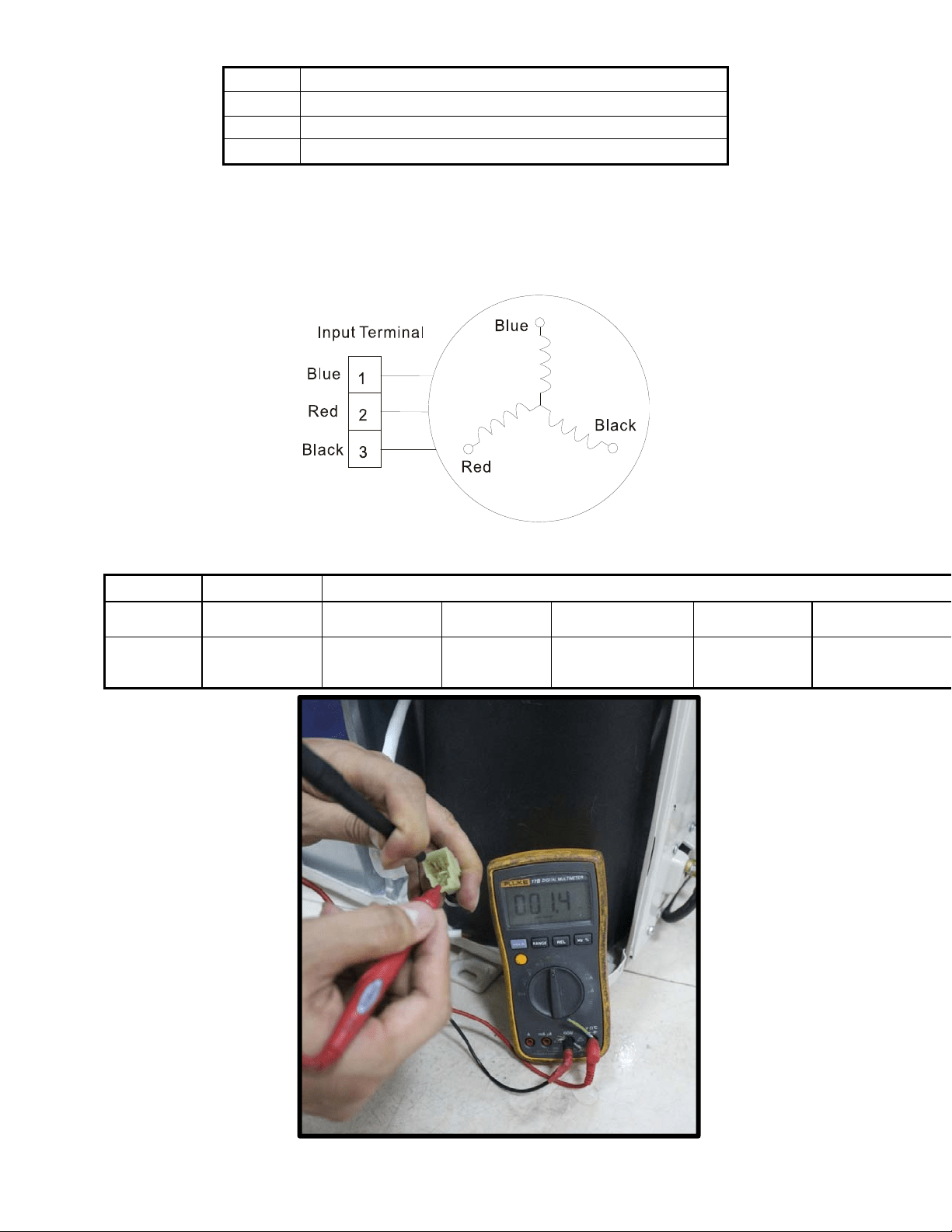
Appendix 3:
℃
10 11 12 13 14 15 16 17 18 19 20 21 22
℉
48 50 52 54 56 58 60 62 64 66 68 70 72
℃
23 24 25 26 27 28 29 30 31 32 33 34 35
℉
74 76 78 80 82 84 86 88 90 92 94 96 98
2. Compressor check
Measure the resistance value of each winding by using the tester.
Position
Resistance Value
ATM150D23UFZ ATF235D22UMT ATF250D22UMT
ATF310D43UMT ATQ360D1UMU ATQ420D1UMU
Blue - Red
1.72Ω 0.75Ω
0.75 Ω
0.65Ω 0.37 Ω 0.38Ω
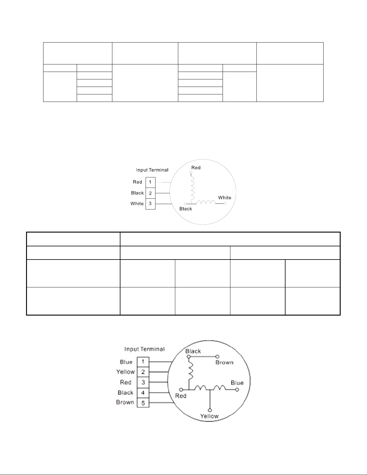
3. IPM continuity check
Turn off the power, let the large capacity electrolytic capacitors discharge completely, and dismount
the IPM. Use a digital tester to measure the resistance between P and UVWN; UVW and N.
Digital tester
Normal resistance
value
Digital tester
Normal
resistance
value
(+)Red (-)Black
∞
(Several MΩ)
(+)Red (-)Black
∞
(Several MΩ)
P
N U
N
U V
V W
W (+)Red
4. AC Fan Motor.
Measure the resistance value of each winding by using the tester.
Position Resistance Value
RPG20B RPG28H
Black - Red
381Ω±8% (20℃)
(Brand: Weiling)
342Ω±8% (20℃)
(Brand: Dayang)
183.6Ω±8% (20℃)
(Brand: Weiling)
180Ω±8% (20℃)
(Brand: Wolong)
White - Black
267Ω±8% (20℃)
(Brand: Weiling)
253Ω±8% (20℃)
(Brand: Dayang)
206Ω±8% (20℃)
(Brand: Weiling)
190Ω±8% (20℃)
(Brand: Wolong)
Measure the resistance value of each winding by using the tester.
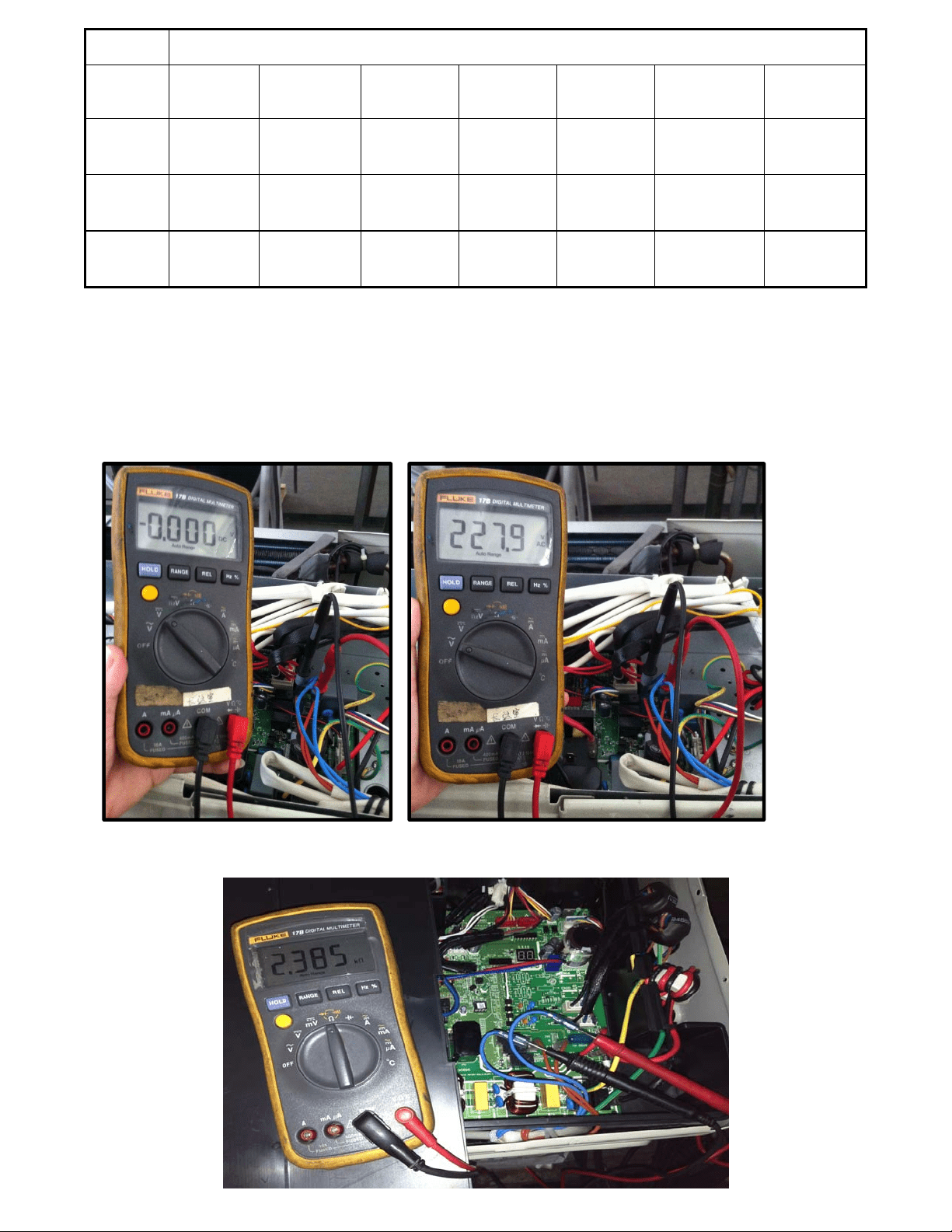
Position Resistance Value
YDK70-
6FB
YDK180-8GB YSK27-4G YSK68-4B YDK45-6B YSK25-6L
YDK53-
6FB(B)
Black -
Red
56Ω±8%
(20
℃)
24.5Ω±8%
(20℃)
317Ω±8%
(20℃)
145Ω±8%
(20℃)
345Ω±8%
(20℃)
627Ω±8% (20
℃)
88.5Ω±8%
(20℃)
Red -
Yellow
76Ω±8%
(20
℃)
19Ω±8% (20
℃)
252Ω±8%
(20℃)
88Ω±8% (20
℃)
150Ω±8%
(20℃)
374.3Ω±8%
(20℃)
138Ω±8%
(20℃)
Yellow -
Blue
76Ω±8%
(20
℃)
19Ω±8% (20
℃)
252Ω±8%
(20℃)
88Ω±8% (20
℃)
150Ω±8%
(20℃)
374.3Ω±8%
(20℃)
138Ω±8%
(20℃)
5.4-way valve
1. Power on, use a digital tester to measure the voltage, when the unit operates in cooling, it is 0V. When
the unit operates in heating, it is about 230VAC.
If the value of the voltage is not in the range, the PCB must have problems and need to be replaced.
2 Turn off the power, use a digital tester to measure the resistance. The value should be 1.8~2.5 KΩ.
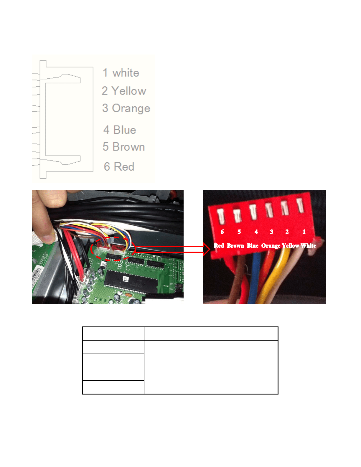
6.EXV check
Disconnect the connectors.
Resistance to EXV coil
Color of lead wire Normal
V
alue
Red- Blue
About 50Ω
Red - Yellow
Brown-Orange
Brown-White
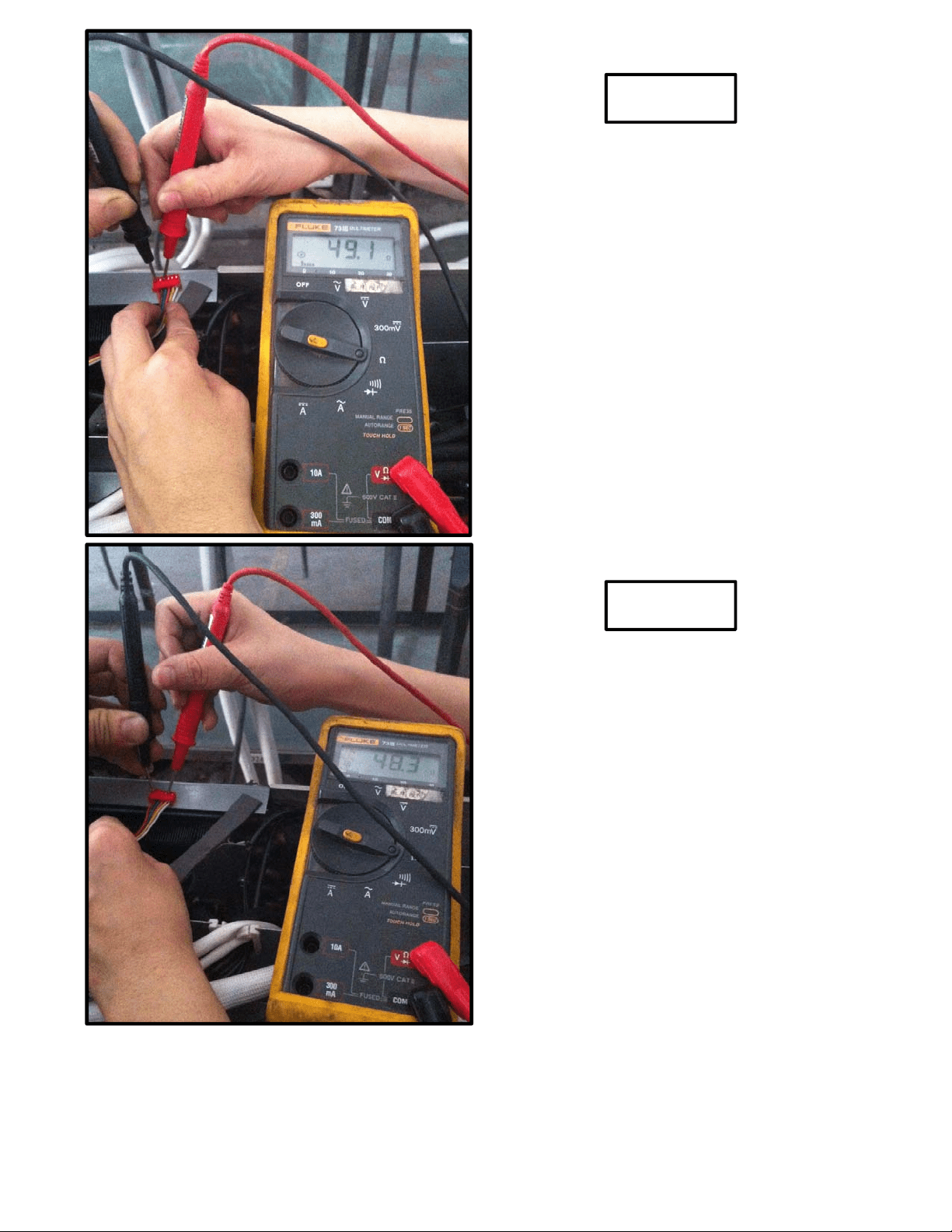
Red- Blue
Red - Yellow
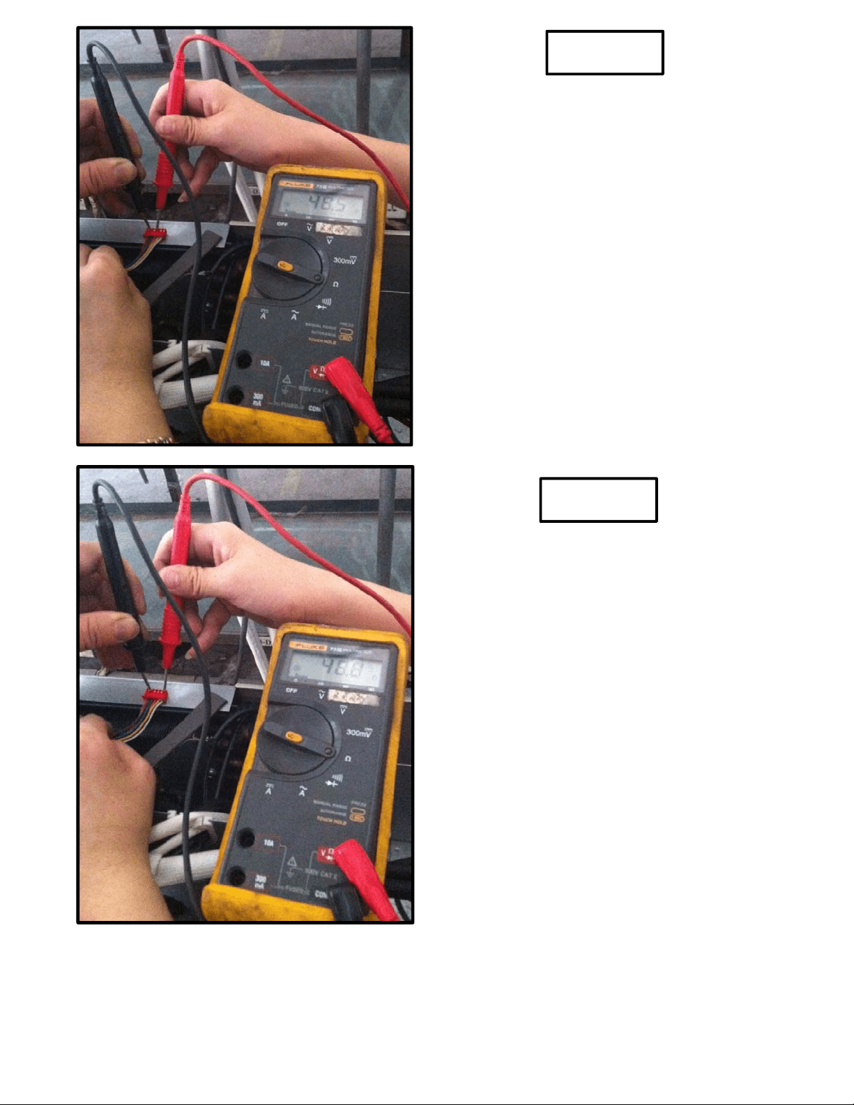
Brown-Orange
Brown-White