Loading ...
Loading ...
Loading ...
98
ASSEMBLY INSTRUCTIONS
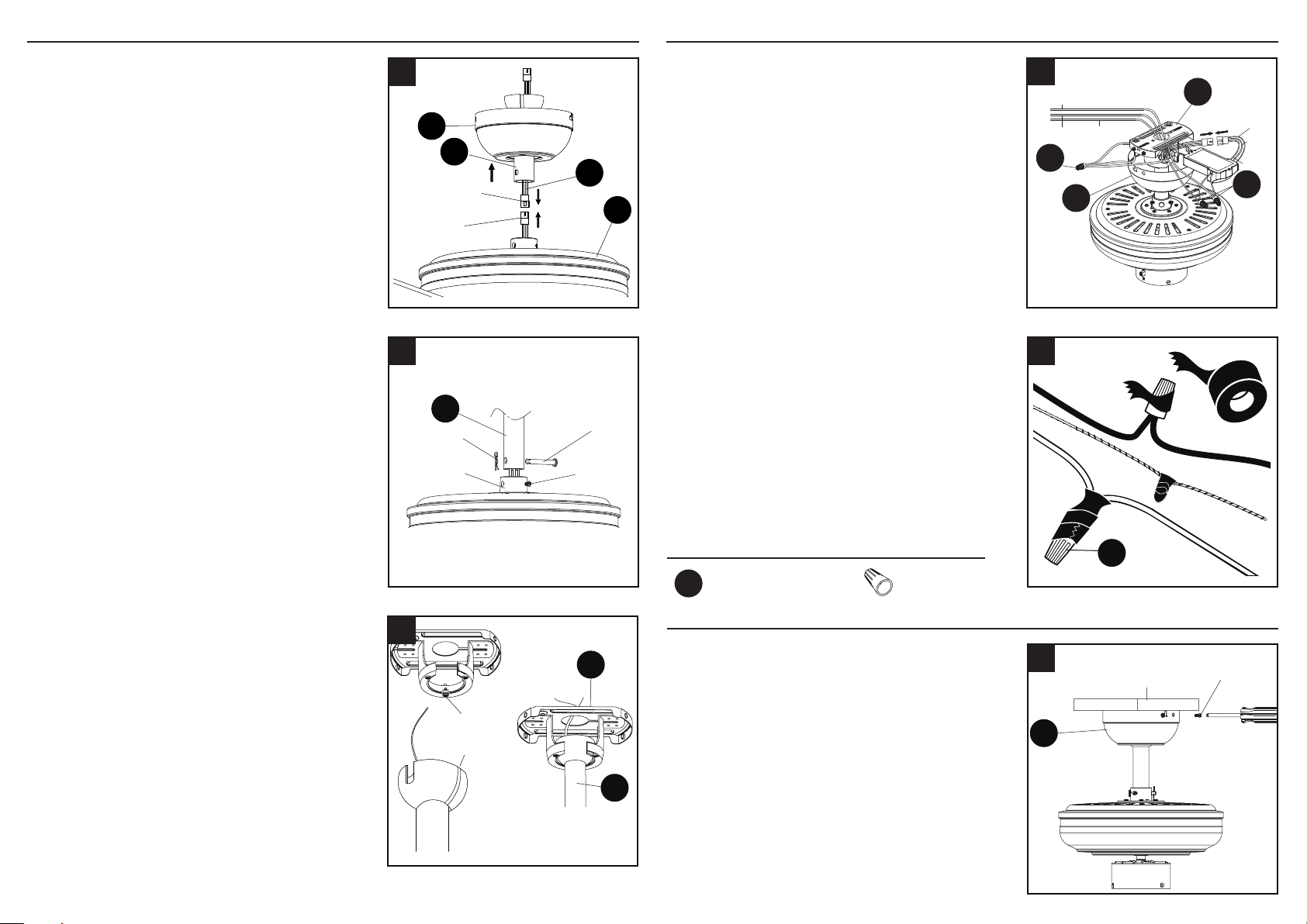
7. Loosen the two set screws from the yoke
of the motor assembly (D). Slip downrod
assembly (C) into yoke, aligning holes
in downrod assembly (C) and yoke.
Insert the pin through yoke and downrod
assembly (C), then insert clip into pin until
it snaps into place. Tighten set screws.
Female plug
B
L
Male plug
C
D
6b
C
Set
Screw
Clip
Pin
Yoke
7
WIRING
6b. EXTENDED DOWNROD INSTALLATION:
If you are installing the fan with a longer
downrod (sold separately), insert it through
the canopy (B). Then, thread lead wire (L)
through the downrod and connect the MALE
plug from the top of the motor assembly (D)
to the FEMALE plug from the lead wire (L).
NOTE: The male plug of the lead wire (L) should
extend out the other end of the downrod.
NOTE: The remainder of the instructions will
reference downrod assembly (C), but note all
of the instructions are applicable even if an
accessory downrod was used.
8. Install hanger ball on the top of downrod
assembly (C) into mounting bracket (A)
opening. Rotate fan until slot on hanger ball
engages the tab on the mounting bracket (A).
Slot
Tab
A
C
8
DANGER: Be careful when aligning the tab
to the slot! If not fully engaged, there is a
possibility of fan falling, which may result in
serious injury or death.
1. Directly align the locking slots of the canopy (B)
with the two screws previously loosened (step
3, page 6) in the mounting bracket (A). Push up
to engage the slots and turn clockwise to lock in
place. Immediately tighten the two screws that
were previously removed (step 3, page 6) to fully
secure the canopy (B) to the mounting bracket (A).
AA
2
Outlet
box
Screw
B
1
2. Twist wire ends together and screw wire connectors
(AA) on in a clockwise direction. Tape wire
connectors (AA) and wires together with electrical
tape (not included).
FINAL INSTALLATION
1. Insert receiver from the remote pack (K) into
mounting bracket (A) with the at side toward the
ceiling. Connect the GREEN/GROUND wire from
the fan to the BARE/GREEN supply wire. Connect
the BLACK wire (AC IN L) from the receiver to the
supply BLACK wire. Connect the WHITE wire (AC IN
N) from receiver to the supply WHITE wire. Connect
FEMALE plug from the receiver to the MALE plug
from the top of motor assembly (D) or the MALE plug
of lead wire (L) if previously installed.
NOTE: BLACK wire is hot power for fan. BLUE wire
is hot power for light kit. WHITE wire is common
for fan and light kit. GREEN wire is ground wire.
If house wires are different colors than referred
to above, stop immediately. Consult a licensed
electrician to determine proper wiring.
Hardware Used
Wire Connector x 3
AA
Blue
White
Black
Black
White
Green/
Ground
Ground/Green
A
B
AA
AA
1
WARNING: Be sure no bare wire or wire strands are
visible after making connection. Place GREEN and
WHITE connections on opposite side of box from
the BLACK and BLUE (if applicable) connections.
The splices should be turned upward and pushed
carefully up into the outlet box.
Loading ...
Loading ...
Loading ...