
Loading ...
Loading ...
Loading ...
ELECTRICAL CONNECTIONS
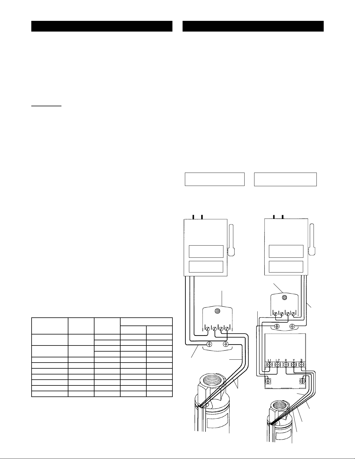
(Figure 9)
WARNING: Electrical precautions
All wiring, electrical connections, AND SYSTEM
GROUNDING MUST comply with the National
Electrical Code (NEC) and with any local codes and
ordinances. A LICENSED ELECTRICIAN SHOULD
BE EMPLOYED.
WARNING: Risk of Electrical Shock
Employ a licensed electrician to do the electrical
wiring. A separate circuit breaker in your home’s
electrical panel is required. A ground fault interrupter
(GFI) protected circuit should be used for all electrical
devices operating near water. Install a properly fused
disconnect switch in the line and make certain the wiring
is adequately sized and well insulated. Undersized
wire between the motor and the power source
will adversely limit the starting and load carrying
abilities of the motor and void warranty. Minimum
wire sizes for motor branch circuits are recommended
in Table 1, Page 3.
For safety, the pump motor must be properly
grounded. For fusing requirements see Table 2.
o Turn off main power supply to pump before
attempting wiring.
o Turn the pressure switch control lever to the “OFF”
position, (if your switch is equipped with a control
lever) disconnecting the switch.
o Remove the cover from the pressure switch by
loosening the cover nut. Connect the wires coming
from the power source to the “LINE” terminals on
the pressure switch. Use no less than 14 gauge
wire to the terminals on the pressure switch.
o Cut the submersible wire cable to length from the
well and connect the wires to the “LOAD” terminals
on the pressure switch.
Table 2 - Circuit Breaker or Fuse Requirements
(SINGLE-PHASES 2- AND 3-WIRE FRANKLIN MOTORS)
Motor
Horsepower
Number
of wires
Voltage
supply
Breaker or fuse size
standard delay
1/3 HP 2 or 3 wire
115 25 10
230 15 5
1/2 HP 2 or 3 wire
115 30 15
230 15 7
3/4 HP 2 or 3 wire 230 20 9
1 HP 2 or 3 wire 230 25 12
1-1/2 HP 2 wire 230 35 15
1-1/2 HP 3 wire 230 30 15
2 HP 3 wire 230 30 15
3 HP 3 wire 230 45 20
5 HP 3 wire 230 70 30
No regular maintenance is required on a submersible
pump. However, it is advisable to check the wiring and
piping annually.
o
Replace the cover on the pressure switch and reset
lever to AUTO if your switch is so equipped.
STARTING THE PUMP
Turn the circuit breaker switch to the “ON” position
to start pump. Pump should start building pressure
immediately. Allow pump to run until water runs clear.
NOTE: If your pressure switch is equipped with a loss of
pressure cut-off switch (with a lever), it will be necessary
for you to hold the lever in the start position until the
pump builds sufficient pressure to remain on without
holding lever in the start position. The pump will run until
system pressure builds up to the cutoff setting of the
switch. The system will operate automatically between
the cut-in and cut-out pressure settings on the switch.
INSTALLATION
FRANKLIN
Control
Box
Service Entrance
115 or 230 Volt
Supply Voltage
(Check your motor nameplate
for proper supply voltage)
Pressure
Switch
Ground
Ground
from
Power
Supply
(Red)
Motor Lead
(Yellow)
Motor Lead
(Black)
Motor Lead
(Green) Ground
wire from Motor
(Black)
Motor
Leads
(Green)
Ground wire
from Motor
Circuit Breaker
or Fused
Disconnect
Switch
Circuit Breaker
or Fused
Disconnect
Switch
PUMP
NAMEPLATE
MOTOR
NAMEPLATE
PUMP
NAMEPLATE
MOTOR
NAMEPLATE
Service Entrance
115 or 230 Volt
Supply Voltage
(Check your motor nameplate for
proper supply voltage)
Wiring Diagram 3-Wire
Motors With Ground
Standard Pressure Switch or
"Loss of Pressure Switch"
Ground from
Power Supply
Figure 9 - Wiring Diagram
Wiring Diagram 2-Wire
Motors With Ground
LINE LOAD LOAD LINE
LINE LOAD LOAD LINE
GND
GND
GND
GND
MAINTENANCE
10
Loading ...
Loading ...
Loading ...