Loading ...
Loading ...
Loading ...
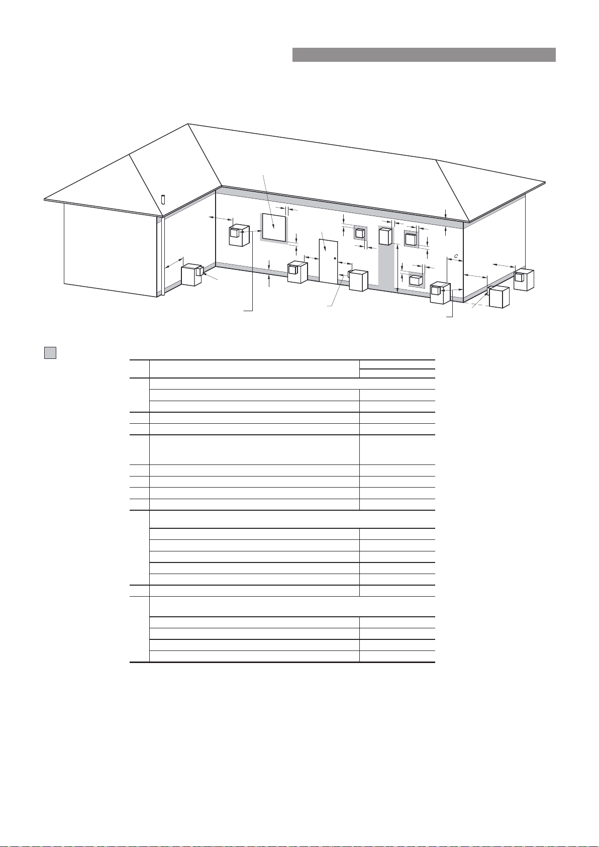
GAS BOOSTER CLEARANCES
Figure 6�2 from AS/NZS5601 is reproduced below� It was current at the time of printing, but may have been
superseded� It is the installer’s responsibility to ensure that current requirements are met�
Shading indicates prohibited ar ea for ue terminals
= Flue terminal
T= Gas meterM
= Mechanical air inlet
I
= Electricity meter or fuse box
P
= Fan-assisted appliance only
Z
Direction of
discharg e
See Note 1
See Note 1
Opening into
a building
T
T
T
T
T
T
C
M
d
d
e
e
h
j
j
j
n
b
f
a
h
P
Z
k
k
g
g
I
T
Door
Fan assisted
• Appliances 002tupni h/JM 05 ot pu
• Appliances 003tupni h/JM 05 revo
b 003* ecafrus rehto ro ynoclab a evoba ,dnuorg eht morF
c 003* renroc lanretxe ro llaw nruter a morF
d
From a gas meter (M) (see Note 5)
(see Clauses 5.11.5.9 for vent terminal location of regulator)
(See Table 6.7 for New Zealand requirements)
1000
e From an electricity meter 005)5 etoN ees( † )P( xob esuf ro
f 57epip lios ro epip niard a morF
g Horizontally from any building structure* or obstruction facing a terminal 500
h From any other flue terminal 003* ekatni ria noitsubmoc ro ,lwoc ,
• Appliances 003* tupni h/JM 051 ot pu
• Appliances 003* tupni h/JM 002 ot pu tupni h/JM 051 revo
• Appliances 005* tupni h/JM 052 ot pu tupni h/JM 002 revo
• Appliances 0051*
tupni h/JM 052 revo
• All fan-assisted flue appliances 0051egrahcsid fo noitcerid eht ni ,
k 0001rewolb aps a gnidulcni ,telni ria lacinahcem a morF
051tupni h/JM 05 ot pu sretaeh ecapS •
• Other appliances 005tupni h/JM 05 ot pu
• Appliances 0001tupni h/JM 051 ot pu dna tupni h/JM 05 revo
• Appliances 0051tupni h/JM 051 revo
1
2
See Clause 6.9.4 for restrictions on a flue terminal
under a covered area.
3
4
5
Minimum clearances d and e also apply to any combustion air intake openings of appliances.
metI.feR
a
Min. clearances (mm)
Below eaves, balconies and other projections:
j
Horizontally from an openable window, door, non-mechanical air inlet, or any other opening into a building
with the exception of sub-floor ventilation:
Vertically below an openable window, non-mechanical air inlet, or any other opening into a building with
the exception of sub-floor ventilation:
NOTES:
† - P
rohibited area below electricity meter or fuse box extends to ground level.
FIGURE 6.2 (in-part) LOCATION OF FLUE TERMINALS OF BALANCED FLUE,
ROOM SEALED, FAN-ASSISTED OR OUTDOOR APPLIANCES
* - unless appliance is certified for closer installation.
n
Where dimensions c, j or k cannot be achieved an equivalent horizontal distance measured diagonally
from the nearest discharge point of the terminal to the opening may be deemed by the Technical
Regulator to comply.
See Figure J3 for clearances required from a flue terminal to an LP Gas cylinder. A flue terminal is
considered to be a source of ignition.
For appliance s not addressed above acceptance should be obtained from the Technical Regulator.
Rinnai 50 CC B OIM
INSTALLATION - GAS BOOSTED SYSTEMS
Loading ...
Loading ...
Loading ...