
Issue
3
Operation Installation Manual
Close Coupled
Solar Hot Water Systems -
Enduro SP200B and
Excelsior SP200BEX Collectors
This system shall be installed in accordance with:
• Manufacturer’s Installation Instructions
• Current AS/NZS 3500
• All applicable local rules and regulations including local OH&S requirements
This system must be installed, commissioned and serviced by an Authorised Person.
Not suitable as a pool or spa heater.
The solar hot and solar cold pipes between the solar storage tank
and the solar collector(s) must be copper tube. Fittings used to
join these pipes must use metallic materials to acheive sealing.
Plastic pipe and fittings must not be used as they are not suitable
for the high temperatures and pressures that may occur.
Failure of plastic pipe and/or fittings can lead to the release of high
temperature water and can cause sever flooding and water damage.
IMPORTANT
All Rinnai gas products
are A.G.A. certified.
W169
SAI Global
AS/NZS 2712
Lic No.1849
SAI Global

Rinnai 2 CC B OIM
TABLE OF CONTENTS
Warnings and Important Information 4
Safety and Regulatory Information ���������������������������������������������������������������������������������������������������������������������4
Scald Hazards ���������������������������������������������������������������������������������������������������������������������������������������������������� 5
Operation Principle ���������������������������������������������������������������������������������������������������������������������������������������������6
Safety Devices ���������������������������������������������������������������������������������������������������������������������������������������������������7
Excessive Discharge from Safety Devices ���������������������������������������������������������������������������������������������������������7
Gas Boosters ������������������������������������������������������������������������������������������������������������������������������������������������������8
Hydrogen Gas ����������������������������������������������������������������������������������������������������������������������������������������������������8
Water Temperature ���������������������������������������������������������������������������������������������������������������������������������������������8
Turning Off the Water Heating System ���������������������������������������������������������������������������������������������������������������8
Turning On the Water Heating System ���������������������������������������������������������������������������������������������������������������8
Water Quality ������������������������������������������������������������������������������������������������������������������������������������������������������9
Draining and Filling the Water Heating System ��������������������������������������������������������������������������������������������������9
Maintenance and Regular Care �������������������������������������������������������������������������������������������������������������������������9
Servicing and Repair ������������������������������������������������������������������������������������������������������������������������������������������ 9
Save a Service Call 10
Specications 12
General �������������������������������������������������������������������������������������������������������������������������������������������������������������12
Cylinder Weights ����������������������������������������������������������������������������������������������������������������������������������������������12
System Dimensions - Stainless Steel Cylinders �����������������������������������������������������������������������������������������������13
System Dimensions - Glass Lined Cylinders ���������������������������������������������������������������������������������������������������14
Solar Collectors ������������������������������������������������������������������������������������������������������������������������������������������������ 15
Gas Boosters ����������������������������������������������������������������������������������������������������������������������������������������������������16
Installation - All Systems 17
Regulations and Occupation Health and Safety (OH&S) ��������������������������������������������������������������������������������17
Location �����������������������������������������������������������������������������������������������������������������������������������������������������������17
Water Pipes, Fittings and Insulation �����������������������������������������������������������������������������������������������������������������18
Water Supply ����������������������������������������������������������������������������������������������������������������������������������������������������18
Hot Water Delivery Temperature ����������������������������������������������������������������������������������������������������������������������19
Valves and Fittings �������������������������������������������������������������������������������������������������������������������������������������������19
System Orientation and Inclination �������������������������������������������������������������������������������������������������������������������20
Roof Mounting Options �������������������������������������������������������������������������������������������������������������������������������������21
Standard Installation �����������������������������������������������������������������������������������������������������������������������������������������24
Roof pitch greater than 30° ������������������������������������������������������������������������������������������������������������������������������28
Framed Installations - Cyclone Frame �������������������������������������������������������������������������������������������������������������29
Framed Installations - Flat, Reverse and Side Pitch ����������������������������������������������������������������������������������������29
Connecting Fittings to Collector �����������������������������������������������������������������������������������������������������������������������31

Rinnai 3 CC B OIM
TABLE OF CONTENTSTABLE OF CONTENTS
180 Litre SS Cylinder with 1 SP200B or SP200BEX Collector - BIKS180CCT01C �����������������������������������������32
180 Litre SS Cylinder with 2 SP200B or SP200BEX Collectors - BIKSUNICCT23C ���������������������������������������34
330 Litre SS Cylinder with 2 SP200B or SP200BEX Collectors - BIKS330CCT02C ��������������������������������������� 36
330 Litre SS Cylinder with 3 SP200B or SP200BEX Collectors - BIKSUNICCT23C ���������������������������������������38
200 Litre Glass Lined Cylinder with 1 SP200B or SP200BEX Collector - BIKV200CCT01C ���������������������������40
200 Litre Glass Lined Cylinder with 2 SP200B or SP200BEX Collectors - BIKV200CCT02C �������������������������42
330 Litre Glass Lined Cylinder with 2 SP200B or SP200BEX Collectors - BIKV330CCT02C �������������������������44
330 Litre Glass Lined Cylinder with 3 SP200B or SP200BEX Collectors - BIKV330CCT03C �������������������������46
Installation - Gas Boosted Systems 48
Gas Booster Location ���������������������������������������������������������������������������������������������������������������������������������������48
Gas Supply �������������������������������������������������������������������������������������������������������������������������������������������������������48
Hot Water Delivery Temperature ����������������������������������������������������������������������������������������������������������������������48
SMARTSTART® �����������������������������������������������������������������������������������������������������������������������������������������������48
System Using Rinnai SmartStart ����������������������������������������������������������������������������������������������������������������������49
Gas Booster Clearances ����������������������������������������������������������������������������������������������������������������������������������50
Installation Procedure ���������������������������������������������������������������������������������������������������������������������������������������51
Filling the System ��������������������������������������������������������������������������������������������������������������������������������������������� 52
Pre Solar Heating Checks �������������������������������������������������������������������������������������������������������������������������������� 52
Solar Heating ����������������������������������������������������������������������������������������������������������������������������������������������������53
Finishing the Installation �����������������������������������������������������������������������������������������������������������������������������������53
Draining Instructions �����������������������������������������������������������������������������������������������������������������������������������������53
Installation - Electric Boosted Systems 54
Installation Procedure ���������������������������������������������������������������������������������������������������������������������������������������54
Filling the System ��������������������������������������������������������������������������������������������������������������������������������������������� 55
Pre Solar Heating Checks �������������������������������������������������������������������������������������������������������������������������������� 56
Solar Heating ����������������������������������������������������������������������������������������������������������������������������������������������������56
Finishing the Installation �����������������������������������������������������������������������������������������������������������������������������������56
Draining Instructions �����������������������������������������������������������������������������������������������������������������������������������������56
Installation Record 57
Notes 58

Rinnai 4 CC B OIM
SAFETY AND REGULATORY INFORMATION
WARNING
DO NOT operate this system before reading the manufacturers instructions�
This appliance must be installed, commissioned and serviced by an authorised person in accordance
with all applicable local rules and regulations�
Access covers of water heating system components will expose 240V wiring and MUST only be removed
by an authorised person�
This appliance is not intended for use by persons (including children) with reduced physical, sensory or
mental capabilities, or lack of experience and knowledge, unless they have been given supervision or
instruction concerning use of the appliance by a person responsible for their safety�
For continued safety of this appliance it must be installed, operated and maintained in accordance with
the manufacturer’s instructions�
Children should be supervised to ensure they DO NOT play with the appliance�
Any power leads from the water heater system components MUST be plugged into an external
weatherproof electrical outlet� If the power supply cord of any water heating components is damaged, it
MUST BE replaced by an authorised person in order to avoid a hazard, using genuine replacement parts
available from Rinnai� Take care not to touch the power plugs with wet hands�
Care should be taken not to touch the pipe work as it may be HOT!
The pipes between the solar collectors and storage cylinder MUST BE copper or an equivalent metallic
material specied by Rinnai. Plastic pipe is NOT suited to the water temperatures and pressures that
may occur in the system�
DO NOT place articles on or against this appliance�
DO NOT store chemicals or ammable materials near this appliance.
DO NOT operate with collectors or covers removed from this appliance�
NEVER use a ammable spray such as hair spray, lacquer, paint, etc near this unit as this may cause a
re.
NOTICE TO VICTORIAN CONSUMERS
This appliance must be installed by a person licensed with the Victorian Building Authority�
Only a licensed person will have insurance protecting their workmanship�
So make sure you use a licensed person to install this appliance and ask for your Compliance Certicate.
For Further information contact the Victorian Building Authority on 1300 815 127��
WARNINGS AND IMPORTANT INFORMATION
WARNINGS AND IMPORTANT INFORMATION

Rinnai 5 CC B OIM
SCALD HAZARDS
HOT WATER CAN CAUSE SCALDS.
CHILDREN, DISABLED, ELDERLY AND THE INFIRM ARE AT THE HIGHEST RISK OF BEING SCALDED.
FEEL WATER TEMPERATURE BEFORE BATHING OR SHOWERING.
SCALDS FROM HOT WATER TAPS CAN RESULT IN SEVERE INJURIES TO YOUNG CHILDREN.
SCALDS OCCUR WHEN CHILDREN ARE EXPOSED DIRECTLY TO HOT WATER WHEN THEY ARE
PLACED INTO A BATH WHICH IS TOO HOT.
ALWAYS......
Test the temperature of the water with your elbow before placing your child in the bath, also carefully
feel water before bathing or showering yourself.
Supervise children whenever they are in the bathroom.
Make sure that the hot water tap is turned off tightly.
CONSIDER.....
Installing child proof tap covers or child resistant taps. Both approaches will prevent a small hand being
able to turn on the tap.
Installing tempering valves or thermostatic mixing valves which reduce the hot water temperatures
deliveredtothetaps.Yourlocalplumbingauthoritymayalreadyrequirethatthesebetted.Contactour
installer or local plumbing authority if in doubt.
NEVER….
Leave a toddler in the care of another child. They may not understand the need to have the water
temperature set at a safe level.
WARNINGS AND IMPORTANT INFORMATION
Rinnai 6 CC B OIM
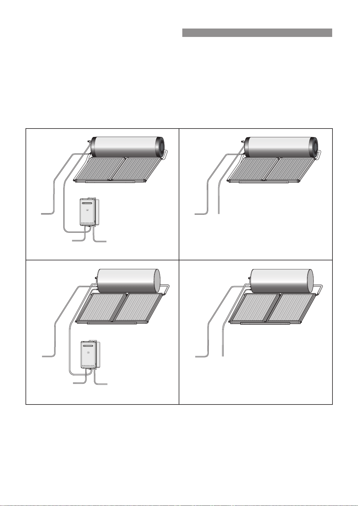
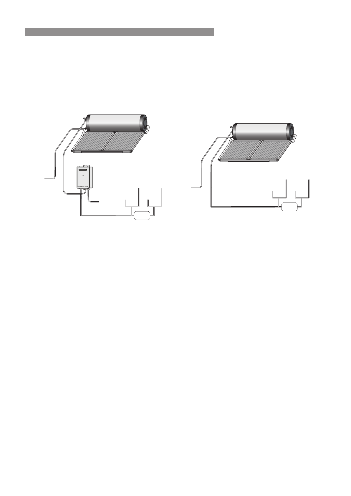
OPERATION PRINCIPLE
Close coupled systems are designed to have the solar collectors on the roof and the storage cylinder above the
collectors, all mounted using available mounting brackets� Electric and gas boosted models are available� The
system comprises of a hot water storage cylinder and solar collectors� Close coupled solar systems use the
thermosyphon principle to circulate the water through the collectors and then to the storage cylinder without the
need for a pump�
Supplementary heating is provided if insufcient heat is available from sun (such as during cloudy or rainy weather
or during winter months) either via an electric heating element located inside the storage cylinder or via a gas
booster located external to the storage cylinder� The following diagrams illustrates the systems set up for electric
and gas boosting�
COLLECTORS
STORAGE CYLINDER
COLD WATER
SUPPLY
HOT WATER
DELIVERY
GAS SUPPLY
GAS BOOSTER
HOT WATER
DELIVERY
COLLECTORS
STORAGE CYLINDER
COLD WATER
SUPPLY
Stainless Steel Gas Boosted Solar Hot Water System Stainless Steel Electric Solar Hot Water System
COLLECTORS
COLD WATER
SUPPLY
HOT WATER
DELIVERY
GAS SUPPLY
GAS BOOSTER
STORAGE CYLINDER
HOT WATER
DELIVERY
COLLECTORS
COLD WATER
SUPPLY
STORAGE CYLINDER
Glass Lined Gas Boosted Solar Hot Water System Glass Lined Electric Solar Hot Water System
WARNINGS AND IMPORTANT INFORMATION
Rinnai 7 CC B OIM
SAFETY DEVICES
The water heating system is supplied with various safety devices including temperature sensors, overheat sensors
and switches and a Pressure & Temperature Relief (PTR) valve� These devices must not be tampered with or
removed. The water heating system must not be operated unless each of these devices is tted and is in working
order�
WARNING
DO NOT tamper with or remove safety devices.
DONOToperatethewaterheaterunlessallsafetydevicesarettedandinworkingorder.
DO NOT block or seal the PTR Valve and drain pipe.
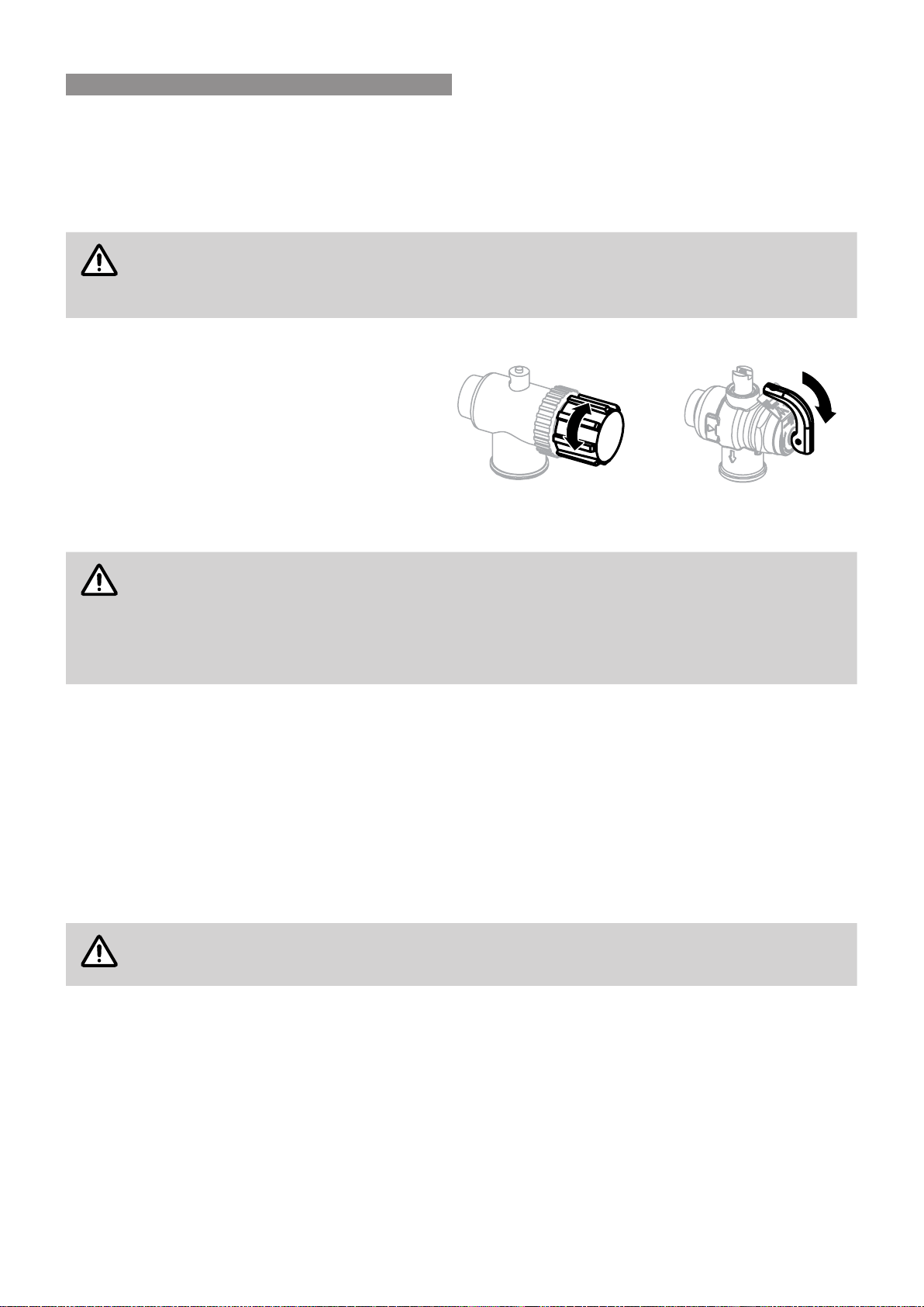
Pressure & Temperature Relief (PTR) Valve
This valve is located near the top of the water heater
and is essential for safe operation� It is normal for the
valve to release a small quantity of water through the
drain line during heating�
However, continuous leakage of water from the valve
and its drain line may indicate a problem with the
water heater�
Twist cap until water
flows from drain line
Lift lever until water
flows from drain line
(Lower lever gently!)
WARNING
Never block the outlet of the PTR valve or it’s drain line for any reason. The easing gear must be
operated at least every 6 months to remove lime deposits and verify that it is not blocked. Failure
to do this may result in the water heater failing.
If the valve does not discharge water when the easing gear lever is opened, or does not seal again
when the easing gear is closed, attendance by an authorised person must be arranged without
delay. The PTR valve is not serviceable.
EXCESSIVE DISCHARGE FROM SAFETY DEVICES
Pressure & Temperature Relief (PTR) Valve
It is normal and desirable that this valve allows a small quantity of water to be discharged during the heating cycle�
If it discharges more than a bucket of water during a 24 hour period or discharges continuously there may be
another problem�
If the valve dribbles continuously, try easing the valve gear for a few seconds as described above� This may
dislodge any foreign matter and alleviate the problem�
If the valve discharges at high ows, especially at night, it may be as a result of the water pressure exceeding the
design pressure of the water heater. Ask your installer to t a Pressure Limiting Valve (PLV).
WARNING
NEVERreplacethePTRvalvewithonewhichhasahigherpressureratingthanisspeciedfor
your water heater.
Expansion Control Valve (ECV) - if tted
It is normal and desirable that this valve allows a small quantity of water to be discharged during the heating cycle�
If it discharges more than a bucket of water during a 24 hour period or discharges continuously there may be
another problem�
If the valve leaks continuously, try easing the valve gear for a few seconds� This may dislodge any foreign matter
and alleviate the problem� If this does not alleviate the problem contact Rinnai�
Operate the easing gear regularly to remove any lime deposits and to verify that it is not blocked�
WARNINGS AND IMPORTANT INFORMATION

Rinnai 8 CC B OIM
GAS BOOSTERS
•
Do not touch the ue outlet or do not insert any objects into the ue outlet.
•
Keep ammable materials, spray cans, fuel containers, trees, shrubs and pool chemicals etc, well clear of
the ue outlet.
•
Do not use the gas types other than those designated on the data plate� For example, do not use Propane/
Butane gas mixtures on appliances marked Propane Gas�
•
Do not use Propane Gas on appliances marked as Natural Gas and vice versa�
HYDROGEN GAS
In the case of systems using a vitreous enamel lined cylinder, if the hot water unit is not used for two weeks or
more, a quantity of hydrogen gas, which is highly ammable, may accumulate in the water heater. To dissipate this
safely, it is recommended that a non electrically operated hot tap be turned on for two minutes at a sink, basin, or
bath, but not a dishwasher or other appliance. During this procedure there must be no smoking, open ame or any
electrical appliance operating nearby� If hydrogen is discharged through the tap, it will probably make a sound like
air escaping�
WATER TEMPERATURE
The water gets heated by the solar energy contributed from the sun and heats the water until the water at the
base of the storage cylinder reaches approximately 65°C� At this time water at the hot outlet can be up to 88°C�
Continued heating is prevented by the ‘No Load’ protection, a Thermo-arrestor (TA) valve that prevents water
passing from the cylinder to the collectors� During periods of low solar gain, supplementary heating occurs�
IMPORTANT
To meet Australian regulatory requirements, supplementary heating must be operational.
TURNING OFF THE WATER HEATING SYSTEM
If you plan to be away for only a few nights, we suggest you leave the water heating system switched on� If it is
necessary to switch off the water heater, do so as outlined below:
Electric Boosted Systems
•
Switch off the electrical supply to the supplementary heating element� The switch is usually marked and
located in the electricity meter box of the dwelling�
Gas Boosted systems
•
Switch off the electric supply to the gas booster�
TURNING ON THE WATER HEATING SYSTEM
Electric Boosted system
•
Switch on the electric supply to the supplementary heating element(s)� The switch is usually marked and
located in the electricity meter box of the dwelling�
Gas Boosted systems
•
Switch on the electrical supply to the gas booster�
WARNINGS AND IMPORTANT INFORMATION

Rinnai 9 CC B OIM
WATER QUALITY
The water quality of most public supplies is suitable for the water heating system� The water quality from bore wells
is generally unsuitable for the water heating system� Refer to the separate warranty document for water quality
parameters and how they affect the warranty conditions� If in doubt about the water quality, have it checked against
the parameters listed in the warranty document� The system is not suitable as a pool or spa heater�
DRAINING AND FILLING THE WATER HEATING SYSTEM
Draining or lling normally occur only during installation or servicing and must be carried out by an authorised
person�
MAINTENANCE AND REGULAR CARE
Operate the easing gear of the PTR as described in the section ‘Safety Devices’ on page 7�
SERVICING AND REPAIR
Our Servicing network personnel are fully trained and equipped to give the best service on your appliance� If your
appliance needs service, ring one of the service contact numbers on the back of this booklet�
It is recommended that the system be serviced at least every 5 years�
The pressure and temperature relief valve and expansion control valve must be checked for performance or
replaced by an authorised person at intervals not exceeding 5 years or more frequently in areas where the water
is classied as scaling water (refer to the supplied warranty booklet).
It is recommended that the sacricial anode tted to Glass Lined cylinders be inspected every 5 years or more
frequently in areas where there is a high incidence of water deposits� This does not apply to Stainless Steel
cylinders� Anodes suited to hard and soft water, are available from Rinnai�
If the electric conduit, power supply cord or plug to the water heater is damaged, they must be replaced by an
authorised person in order to avoid a hazard. The power supply cord and plug (if tted) must be replaced by a
genuine replacement part available from Rinnai�
WARNINGS AND IMPORTANT INFORMATION

Before contacting Rinnai for service, please follow the fault nding guide. If the problem persists or this information
doesn’t answer your questions, contact Rinnai on the phone number on the back of this manual
Service call outs attending to any condition or fault that is not related to Rinnai product or components may be
chargeable�
INSUFFICIENT OR NO HOT WATER
Excessive hot water
consumption
Electric Boosted Systems:
Often people are surprised at the amount of hot water used, especially when
showering� If the amount of hot water used during the day exceeds the storage capacity
of the cylinder, it is likely that there will be insufcient hot water.
Gas Boosted Systems:
Insufcient ow may occur if multiple outlets are in use at the same time and exceed
the rated ow capacity of the gas booster. If so, reduce the number of outlets in use.
Consider discussing with your installer, tting water saving xtures and/or ow control
or pressure limiting valves to reduce consumption�
Incorrect solar system size The system may not have been adequately sized to suit the household�
Temperature and pressure
relief valve / expansion
control valve discharging
water continuously
PTRValves&ECVValves(iftted)
It is normal and desirable that these valves allows a small quantity of water to be
discharged during the heating cycle� If they discharges more than a standard bucket
of water during a 24 hour period or discharges continuously there may be another
problem
If water continuously dribbles from the valve, try easing the valve gear for a few
seconds as described in
the section ‘Maintenance and Regular Care’ on page 9�
This may dislodge any foreign matter and alleviate the problem�
If the valve discharges at high ows, contact your installer or Rinnai to discuss.
Booster heating not
operating for electric
systems
Electric boosted Systems:
Check to ensure the electric isolating switch(es) at the switchboard (usually marked
“Hot water” or “water heater”) is switched ‘ON’�
Check to ensure that the electric fuses for hot water at the switchboard are intact
If running on Off-Peak, discuss boosting times with electricity supplier�
Booster heating not operating or insufcient gas supply for gas boosted heating system
Gas booster not operating
orinsufcientgassupply
for gas boosted heating
system
Gas Boosted Systems:
Check to ensure the power cord of the gas booster is plugged in and switched ‘on’�
Check gas is available and the isolation valve is opened
Close the hot tap and wait for 10 seconds and open it again� The hot tap must be
opened enough to ensure that the ow rate is sufcient for the gas booster to light.
Check if there is gas supply to other appliances in the rest of the house
Booster thermostat settings Electric Boosted Systems:
Check the temperature of hot water delivered with a thermometer placed under the
closest outlet (usually the kitchen sink) on a non-tempered hot water line
This test should be done early in the morning after overnight electrical boosting before
any hot water is used� The temperature of the water delivered should be at least 55°C
(allowing for heat losses in pipe work)
If this is not the case or the temperature may need to be increased� Contact your
installer or Rinnai to discuss adjusting the thermostat.
NO WATER FROM THE HOT TAP
Restriction in the hot tap
or failure of the cold water
supply to the heater
Check for water ow at the other hot taps and that the cold water isolation valve is fully
open
Rinnai 10 CC B OIM
SAVE A SERVICE CALL

HIGH ELECTRICITY OR GAS BILL
Hot water usage patterns Electric Boosted Systems:
If using an off peak (overnight) boosted electrical system, the time of use of the water
may affect whether heating is done by electric element or solar energy� This is because
both solar heated water and electrically heated water are stored in the same cylinder�
As the element is in the middle of the tank, half the tank can be heated each night by
the booster element�
If the bulk of hot water is used in the morning, there will be cold water in the cylinder for
the sun to heat during the day leading to lower electricity usage�
If the bulk of the hot water is used in the evening, the electric element will reheat the
water overnight� In the morning there will only be half a cylinder of cold water for the
sun to heat�
Consider changing your usage pattern to optimise solar energy usage�
High electricity cost Electric Boosted Systems:
The electricity tariff will determine the running costs of the system� Contact the
electricity supplier to conrm what these tariffs are.
Temperature and pressure
relief valve / expansion
control valve discharging
water continuously
See entry under ‘Insufcient or No Hot Water’
Lack of solar gain Reduced sunlight due to overcast weather in summer or low solar contribution in winter
will result in an increased dependence on electricity or gas boosting� Higher electricity
or gas bills under these conditions, especially in winter, are normal�
If the solar collectors are shaded by trees or other objects, or the glass is dirty, the
effectiveness of the collectors is greatly reduced� Arrange for trimming of the trees or
relocation of the solar collectors if the obstruction is permanent� Arrange for cleaning of
the collector glass
Solar collectors incorrectly positioned will also severely affect the solar gain� Check that
positioning and alignment of solar collectors is in accordance with the section ‘System
Orientation and Inclination’ on page 20�
CONDENSATION IN COLLECTORS
Condensation in solar
collectors
There is a small amount of ventilation between atmosphere and the internals of the
solar collector to ensure efcient operation. Under certain weather conditions, water
vapour naturally present in the air may condense on the inside surface of the collector
glass� This does not affect the performance of the system� If you are concerned contact
Rinnai to discuss�
NOISY SOLAR COLLECTORS
Noise from solar collectors Occasionally on days of high solar gain, the water temperature in the collector may
become very high� The noise may be similar to a boiling kettle, or an expanding
contracting metallic sound� The collector is designed to withstand these conditions, and
no action is needed, unless it is extreme� Contact Rinnai to discuss if you have any
concerns�
WATER HAMMER
Hot and cold water
plumbing in the premises
Contact your installer or a plumber to discuss checking the clipping of hot and cold
water pipe work and install a pressure limiting valve or water hammer arrestor as
required
Rinnai 11 CC B OIM
SAVE A SERVICE CALL

GENERAL
Close Coupled hot water systems are specied according to the cylinder capacity, number of solar collectors and
boost type and capacity� Boost capacity for gas boosted system depends on the gas booster model selected�
Boost capacity for electrically boosted systems depends on the power rating of the electric heating element�
Specications for the various components are shown below.
Solar ow and return connection: Rp ¾
PTR valve connection: Rp ¾
Cold inlet connection: Rp ¾
Hot outlet connection: Rp ¾
PTR valve setting 850 kPa
Rating of PTR Valve supplied 10 kW
Expansion Control Valve (ECV) setting
(supplied by installer if required)
700 kPa
Max supply pressure with ECV 500 kPa
Max supply pressure without ECV 700 kPa
Pressure limiting valve rating
(supplied by installer if required)
500 kPa
Electric element power rating
2�4 or 3�6 kW standard
1�8 or 4�8 kW available for stainless steel cylinders
4�8 kW available for glass lined cylinders
CYLINDER WEIGHTS
Mass of Cylinder
(empty)
Mass of Cylinder
(lled)
Stainless steel 180 litre 40 kg 225 kg
Stainless steel 330 litre 80 kg 412 kg
Glass lined 200 litre 77 kg 277 kg
Glass lined 330 litre 104 kg 434 kg
Rinnai 12 CC B OIM
SPECIFICATIONS
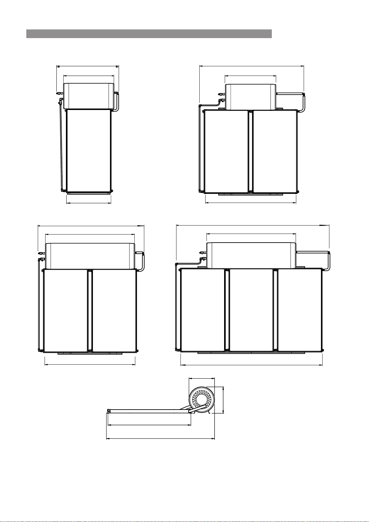
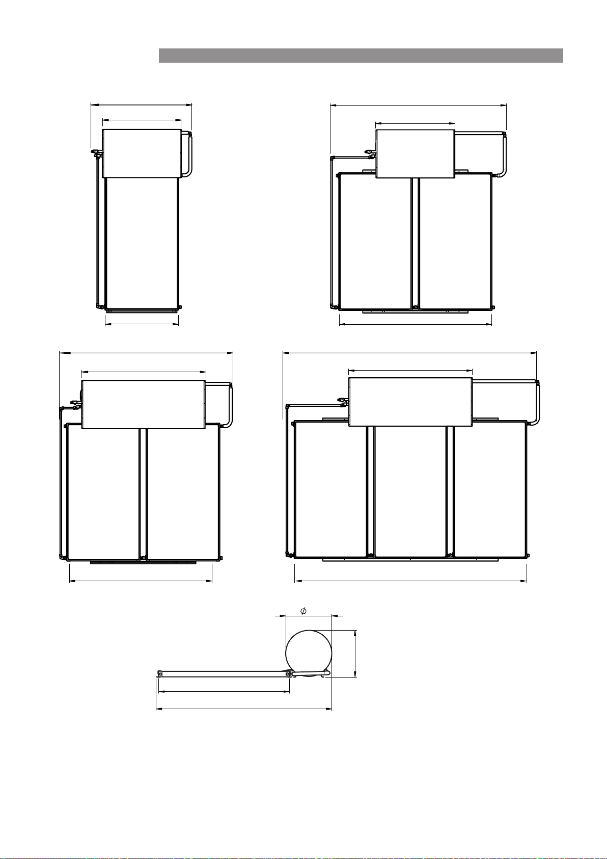
SYSTEM DIMENSIONS - STAINLESS STEEL CYLINDERS
1050
1200
1450
2090
2470
2175
2090
3600
3310
600
610
1960
2580 *
* This dimension may vary slightly depending on the installed
spacing between the cylinders and the collectors�
2470
1200
2175
Rinnai 13 CC B OIM
SPECIFICATIONS
SYSTEM DIMENSIONS - GLASS LINED CYLINDERS
2470
1735
1430
1140
3610
1735
1050
2175
3310
1960
2610 *
695
1140
2470
2175
685
* This dimension may vary slightly depending on the installed
spacing between the cylinders and the collectors�
Rinnai 14 CC B OIM
SPECIFICATIONS

SOLAR COLLECTORS
ENDURO
SP200B
EXCELSIOR
SP200BEX
Type Flat plate Flat Plate
Waterways Copper Copper
Absorber Aluminium Copper
Selective Surface High Performance Sputtered Titanium Oxide
Maximum Operating Pressure 1000 kPa 1000 kPa
Casing Material Aluminium Aluminium
Overall Dimensions
(L x W x H) (mm)
1960 x 1050 x 80 1960 x 1050 x 80
Weight empty (kg) 40 40
Water volume (litres)
1�95 2�0
Number risers 9 10
Potential Solar Output at
PTR relief conditions (kW)
1�25 kW 1�25 kW
Frost Protection
The Rinnai solar hot water warranty booklet species the locations and
conditions that apply for at plate collectors to be warranted against frost
damage�
In locations where the warranty booklet species that frost valves must be
used, they must be tted for warranty to apply. If frost valves are missing
you must obtain them and t them. Failure to t frost valves will void any
warranty against frost damage�
For full warranty terms, conditions and exclusions refer to the Rinnai
warranty booklet for solar hot water�
This booklet is available at www�rinnai�com�au�
Rinnai 15 CC B OIM
SPECIFICATIONS

GAS BOOSTERS
Model Name S20 S26 S26i* S32*
Boost capacity at 20°C rise (l/min) 20 26 32 37
Boost capacity at 25°C rise (l/min) 16 26 26 32
Maximum rated ow (l/min) 20 26 32 37
Minimum water supply pressure for maximum rated
ow (kPa)
1
120 200 140 180
Frost protection Yes
Gas consumption maximum (MJ/h) 125 199 195 250
Gas consumption minimum (MJ/h) 14 14 16 21
Hot water delivery temperature (°C)
2
70
Dimensions - height x width x depth (mm) 530 x 350 x 194
600 x 470 x
244
Weight (kg) 15 21 21 29
1 Units will operate at lower pressures but the rated ow will not be achieved.
2 Gas boosters for Solar hot water applications must be set by Rinnai to deliver a minimum temperature of 70°C� Solar
Gas boosters will be marked as Solar� Units not marked ‘Solar’ MUST NOT be used, and will invalidate warranty� See
warranty booklet for more details�
* These models are made to order�
Rinnai 16 CC B OIM
SPECIFICATIONS

REGULATIONS AND OCCUPATION HEALTH AND SAFETY (OH&S)
WARNING
Installation and commissioning must be performed by authorised persons�
Solar systems must be installed in accordance with these instructions and all regulatory requirements
which exist in your area including those in relation to manual lifting, working at heights and on roofs�
Applicable publications and regulations may include:
•
AS/NZS 5601 Gas Installations
•
AS/NZS 3500 National Plumbing and Drainage
•
AS/NZS 3000 Wiring rules
•
Building Codes of Australia (BCA)
•
Local Occupational Health and Safety (OH&S) regulations
This appliance is not suitable for use as a domestic spa pool or swimming pool heater�
Solar collectors and cylinders are heavy and bulky items and are usually positioned on the roofs of
buildings� Australian State and Territories have a principal Occupational Health and Safety (OH&S)
Act which contains requirements relating to the handling of large, bulky or awkward items and the
prevention of falls from elevated surfaces� Persons installing solar collectors must be aware of their
responsibilities and be adequately trained and qualied, in accordance with local OH&S requirements.
LOCATION
System Location
WARNING
These systems are only suitable for use on buildings up to 10 metres tall�
Select suitable areas of roof on which to install the solar collectors and cylinder� It is essential that the roof structure
is suitable for the solar collector/cylinder combination and can support the weight of these items when full of water�
It is the installers responsibility to ensure the roof can safely support the system and to visually check the roof,
and if there is any damage that requires attention (such as cracked tiles etc�), to inform the owner� If this affects
the safe installation of any part of the system, installation should not proceed until the damage has been rectied.
Collectors should be positioned for optimum solar benet. Refer to the section ‘System Orientation and Inclination’
on page 20 for more information�
All system components must be in an accessible location. Sufcient clearances shall allow access to, and removal
of, all serviceable parts. Ensure the PTR valve, drain lines, thermostats and elements have sufcient clearances
and are accessible for service and removal� The information on any data plates must also be readable�
All electrically boosted solar hot water heating elements must be connected to an independent, fused, AC 240V 50
Hz power supply with an isolating switch installed at the switch board�
Gas Booster Location (where applicable)
The S20, S26 and S32 gas boosters are designed for outdoor installation only� As such, they must be located in an
above ground open air situation with natural ventilation, without stagnant areas, where gas leakage & products of
combustion are rapidly dispersed by wind and natural convection� If an internal model which has been converted
to a solar gas booster follow information supplied with the unit for location, mounting and ueing requirements.
Rinnai 17 CC B OIM
INSTALLATION - ALL SYSTEMS

WATER PIPES, FITTINGS AND INSULATION
IMPORTANT
The solar hot and solar cold pipes between the solar storage tank and solar collector(s) must be
copper tube. Fittings used to join these pipes must use metallic materials to achieve sealing. Plastic
pipe and ttings must not be used as they are not suitable for the high temperatures and pressures
that may occur. Failure of plastic pipe and/or ttings can lead to the release of high temperature water
and can cause severe ooding and water damage.
All hot water pipework should be insulated with sealed polyethylene foamed or equivalent insulation to optimise
performance and energy efciency, and to protect against frost damage. Such insulation may also be mandatory
under local regulations�
Rinnai recommend insulation to achieve at least the R value shown in the following table�
Location of Installation
Hot pipe between tank
and collectors
and
Pipe between tank and
gas booster
Cold pipe between tank
and collectors�
(the side with the TA
valve)
• CER Zone 4
• Areas dened as “B or “C” in the latest version
of the Rinnai Solar Hot Water Warranty Booklet�
• Any other area prone to frost conditions�
R = 0�6 K�m²/W R = 0�6 K�m²/W
• All other areas R = 0�6 K�m²/W insulation not required
With the exception of solar collector ow and return pipes, water pipe sizing should be performed in accordance
with AS/NZS 3500�
All supplied insulation materials must be tted as shown to minimise heat losses. In frost prone areas this insulation
will also protect against frost damage. If frost valves are tted they must remain free of any insulation materials.
Frost valves must be exposed directly to ambient air conditions to ensure correct operation�
WATER SUPPLY
The maximum water pressures for the various systems are listed on page 12� Approved pressure limiting valves
may be required if the ‘Maximum’ rated water supply pressures are exceeded� For gas boosted systems to achieve
the rated ow through the outlet of the continuous ow water heater, the minimum water supply pressures must be
supplied. The systems will operate at lower pressures but the rated ow will not be achieved.
Water chemistry and impurity limits are detailed in the separate warranty booklet� Most metropolitan water supplies
fall within these requirements� If you are unsure about water quality, contact your water authority� If sludge or
foreign matter is present in the water supply, a suitable lter should be incorporated in the water supply to the
storage cylinder�
Rinnai 18 CC B OIM
INSTALLATION - ALL SYSTEMS
HOT WATER DELIVERY TEMPERATURE
Local regulations and/or the requirements of AS/NZS 3500�4 must be considered regarding the temperature
limitations of hot water supplied to areas used primarily for personal hygiene� The temperature of water to these
areas is limited to 45°C for early childhood centres, primary and secondary schools and nursing homes or similar
facilities for young, aged, sick or people with disabilities and 50°C for all other buildings� To comply with these
requirements, a temperature limiting device, such as a thermostatic mixing or tempering valve, will be required on
all solar hot water systems as detailed below�
COLD WATER
SUPPLY
HEATED WATER
FROM STORAGE
CYLINDER
GAS SUPPLY
KITCHEN
LAUNDRY
ENSUITE
BATHROOM
TEMPERATURE
LIMITING
DEVICE
HEATED WATER
FROM STORAGE
CYLINDER
COLD WATER
SUPPLY
KITCHEN
LAUNDRY
ENSUITE
BATHROOM
TEMPERATURE
LIMITING
DEVICE
Tempered Gas Hot Water System Tempered Electric Hot Water System
VALVES AND FITTINGS
The following valves and ttings are supplied with your solar hot water system:
•
A combined pressure and temperature (PTR) relief valve, capacity 10 kW� Relief valve pressure settings
vary with models. This valve is tted at the top of the storage cylinder. The PTR valve is a safety device and
it is mandatory that it is tted by the installer in all installations.
•
Thermo-Arrestor (TA) valve. This valve is tted on the inlet pipe to the solar collectors. Its function is to
control the ow of water from the tank to the collectors and stop the ow of water when the tank has reached
the required temperature�
•
For gas boosted systems, elbow connections for the hot, cold and gas supply are tted at the bottom of the
gas booster�
•
Fittings as shown on pages 32 to 47
The following valves & ttings are to be supplied by the installer:
•
A cold water expansion control valve (ECV). An ECV must be tted in Western Australia and South Australia
to the cold water supply to the storage cylinder to comply with local regulations� An ECV is recommended
in all other geographical areas where the water supply has a tendency to cause scaling� This will reduce hot
water discharge from the pressure and temperature relief (PTR) valve which minimises wear on this valve�
•
A stop cock, non return valve and line strainer� Combination valves incorporating two or more of these
functions (such as ‘Trio’ valves) are suitable. These are tted to the cold water supply to the storage cylinder
by the installer�
•
Cold water supply and hot water discharge pipework to and from the storage cylinder�
•
An isolating valve and connection union for the gas supply to the gas booster�
•
An approved pressure limiting valve (supplied with some systems) is required if the maximum rated water
supply pressure on page 12 is exceeded�
Rinnai 19 CC B OIM
INSTALLATION - ALL SYSTEMS

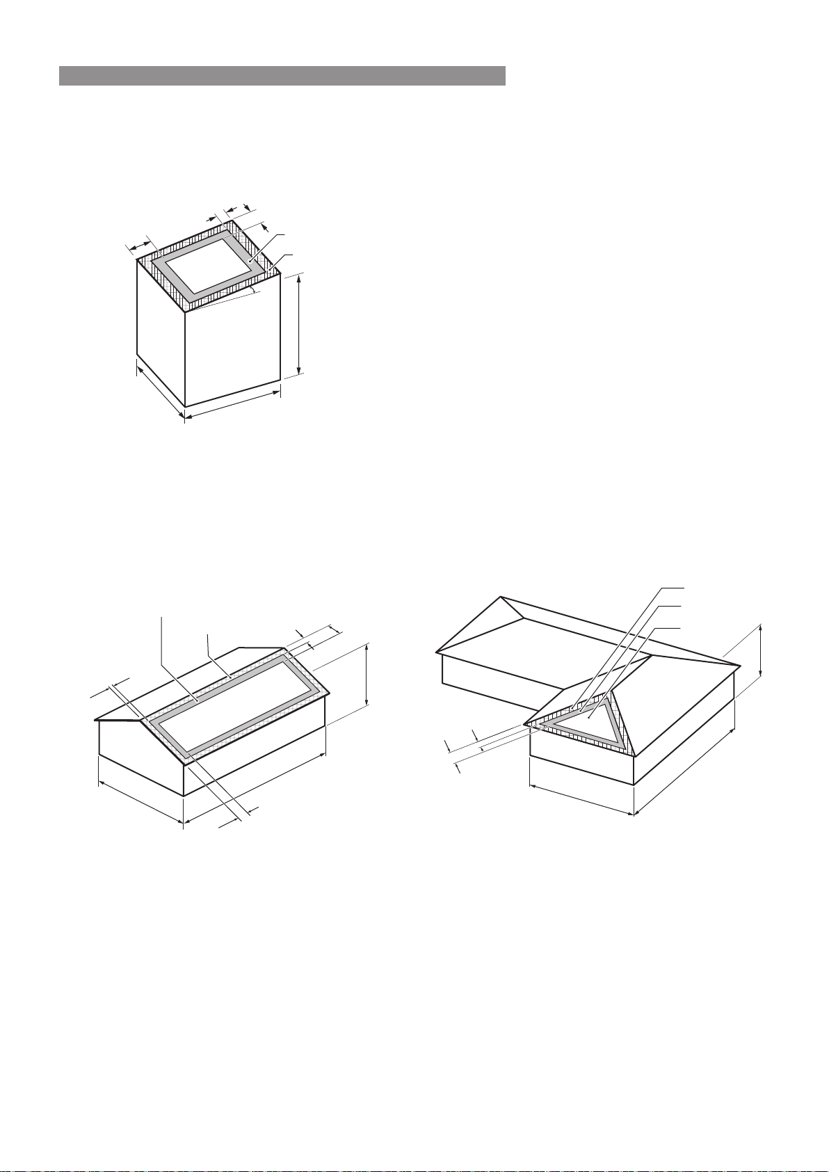
SYSTEM ORIENTATION AND INCLINATION
The performance of any solar hot water system is determined by the way the system is installed�
For Australian installations, solar collectors should face the equator (True North) for optimum performance�
Installing solar collectors facing up to 45 degrees away from North (between North-East and North-West) will
reduce efciency by approximately 5%.
For Australian installations, the inclination of solar collectors should be the same as the latitude of the site for
optimum performance. Inclinations within 20 degrees of the latitude of the site will reduce efciency by approximately
5%. Most roofs in Australia have a slope of between 20° and 25° and provide an appropriately angled mounting
surface�
Installers must ensure they comply with relevant local regulations regarding solar collector inclination
and orientation.
City Latitude City Latitude City Latitude
Adelaide
35
°S
Canberra
35
°S
Melbourne
38
°S
Albany
35
°S
Darwin
12
°S
Perth
32
°S
Alice Springs
24
°S
Dubbo
32
°S
Port Hedland
20
°S
Brisbane
27
°S
Geraldton
28
°S
Rockhampton
24
°S
Broken Hill
31
°S
Hobart
42
°S
Sydney
34
°S
Cairns
17
°S
Mildura
34
°S
Townsville
19
°S
Latitudes of Australian Cities
Rinnai 20 CC B OIM
INSTALLATION - ALL SYSTEMS
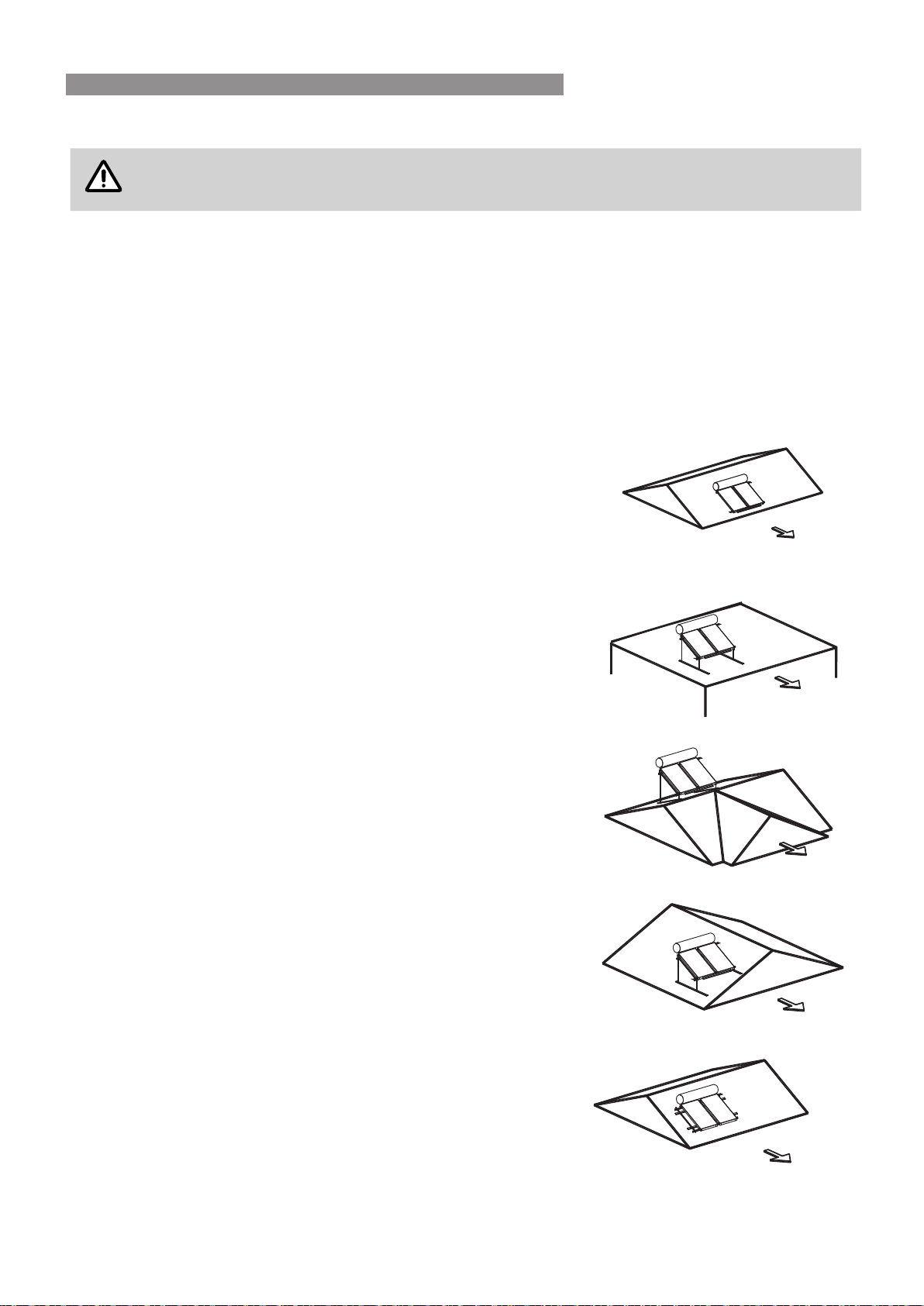
ROOF MOUNTING OPTIONS
WARNING
These systems are not suitable for use on roofs over 10 m high�
For roofs with a slope of 10° or less a at roof frame must be used.
Rinnai do not recommend installing Close Coupled systems on roofs with a pitch greater than 30°� An additional
strap should be used to prevent the cylinder from tipping over if a system is installed in this manner� Refer page
28�
It is normal to mount the solar collectors down close to the gutter� Roof construction must be checked to ensure
that the roof timbers are capable of supporting the additional load� (Refer to AS 3500�4 Appendix H)�
For tiled roof installations� Check for cracked or damaged tiles in the area of proposed installation� Replace any
faulty tiles� If spare tiles are not available, swap damaged tiles with good ones from along the gutter line�
Standard Installation
Installation details are in this manual�
N
Flat Roof Frame
Additional information is provided in the roof frame manual provided with
the frame�
N
Reverse Pitch Frame
Additional information is provided in the roof frame manual provided with
the frame�
N
Side Pitch Frame
Additional information is provided in the roof frame manual provided with
the frame�
N
Cyclone Frame
Additional Information is provided in the manual provided with the cyclone
frame
N
Rinnai 21 CC B OIM
INSTALLATION - ALL SYSTEMS
Mounting Location Suitability
The following table indicates which installation locations are suitable for different roof mounting options for Rinnai
close coupled solar hot water systems�
Wind Region
Region
A
Region
B
Region
C
Region
D
Roof Area
(see page 23 for
explanation)
Area
1
Area
2
Area
3
Area
1
Area
2
Area
3
Area 1
Areas
2 & 3
Area 1
Areas
2 & 3
Pitched roof
ü ü ü ü ü û û û û û
Flat roof frame
ü ü û ü û û ü* û ü* û
Reverse or side pitch
frame
ü û û û û û û û û û
* See cyclone frame manual for full details of mounting location suitability in cyclone areas�
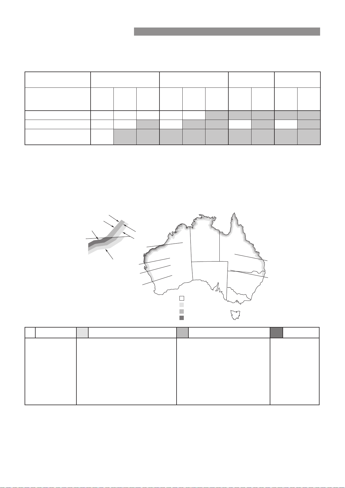
Wind Region
Australia has been categorised into 4 wind regions� Each region has varying wind load parameters such as wind
speed and wind direction multipliers� The diagram below illustrates the region locations� For more information
on how to classify site specic wind loading parameters see AS/NZS 1170.2 - Wind Actions, or consult a certied
structural engineer�
20˚
25
˚
25˚
30˚
27˚
30˚
50km
100km
150km
Region A
Region B
Region C
Region D
Region A Region B Region C Region D
Callytharra Springs
Gascoyne Junction
Green Head
Kununurra
Lord Howe Island
Morawa
Toowoomba
Wittanoom
Bourke
Adelaide River
Atherton
Biloela
Brisbane
Christmas Island
Collinsville
Corindi
Geraldton
Ivanhoe
Kyogle
Marble Bar
Mullewa
Norfolk Island
Torres Strait Islands
Wyndham
Borroloola
Broome
Bundaberg
Burketown
Cairns
Cocos Islands
Darwin
Derby
Karumba
Mackay
Mareeba
Millstream
Moreton
Nhulunbuy
Normanton
Rockhampton
Townsville
Carnarvon
Exmouth
Karratha
Onslow
Port Hedland
Indicative selection of towns in Regions A,B,C &D
Rinnai 22 CC B OIM
INSTALLATION - ALL SYSTEMS
Roof Area
As per AS/NZS 1170.2, domestic pitched and at roof areas are classied into working areas. The diagram below
illustrate these areas�
Area 1
Area 2
Area 3
30° MAX
h = Average height
of building
D
A
B
A
A/2
A=minimumof0.2xB,0.2xDand1xh
Area 1 - Internal of roof�
Area 2 - Intermediate area, wind pressures increased
by 1�5 times�
Area 3 - Roof edge including corners, wind pressures
increased by 3 times� For installations in roof area
3, a minimum of 0�5m from the edge of the roof is
recommended�
Height limit for all installations is 10 metres�
For more information on how to classify specic roof
area installations, or for building heights exceeding
10 metres see AS/NZS1170.2 or consult a certied
structural engineer�
Some examples are shown below�
Example 1
3.8 (h)
1.21 (A/2)
2.42 (A)
Area 3
12.1 (D)
20.3 (B)
1.21 (A/2)
2.42 (A)
Area 2
Area 1
Example2
12.1 (D)
20.3 (B)
3.8 (h)
2.42 (A)
1.21 (A/2)
Area 3
Area 2
Area 1
In both examples :
A = min of 0�2 x 20�3 = 4�06
0�2 x 12�1 = 2�42
1 x 3�8 = 3�8
è A = 2�42
A/2 = 1�21 m
Rinnai 23 CC B OIM
INSTALLATION - ALL SYSTEMS
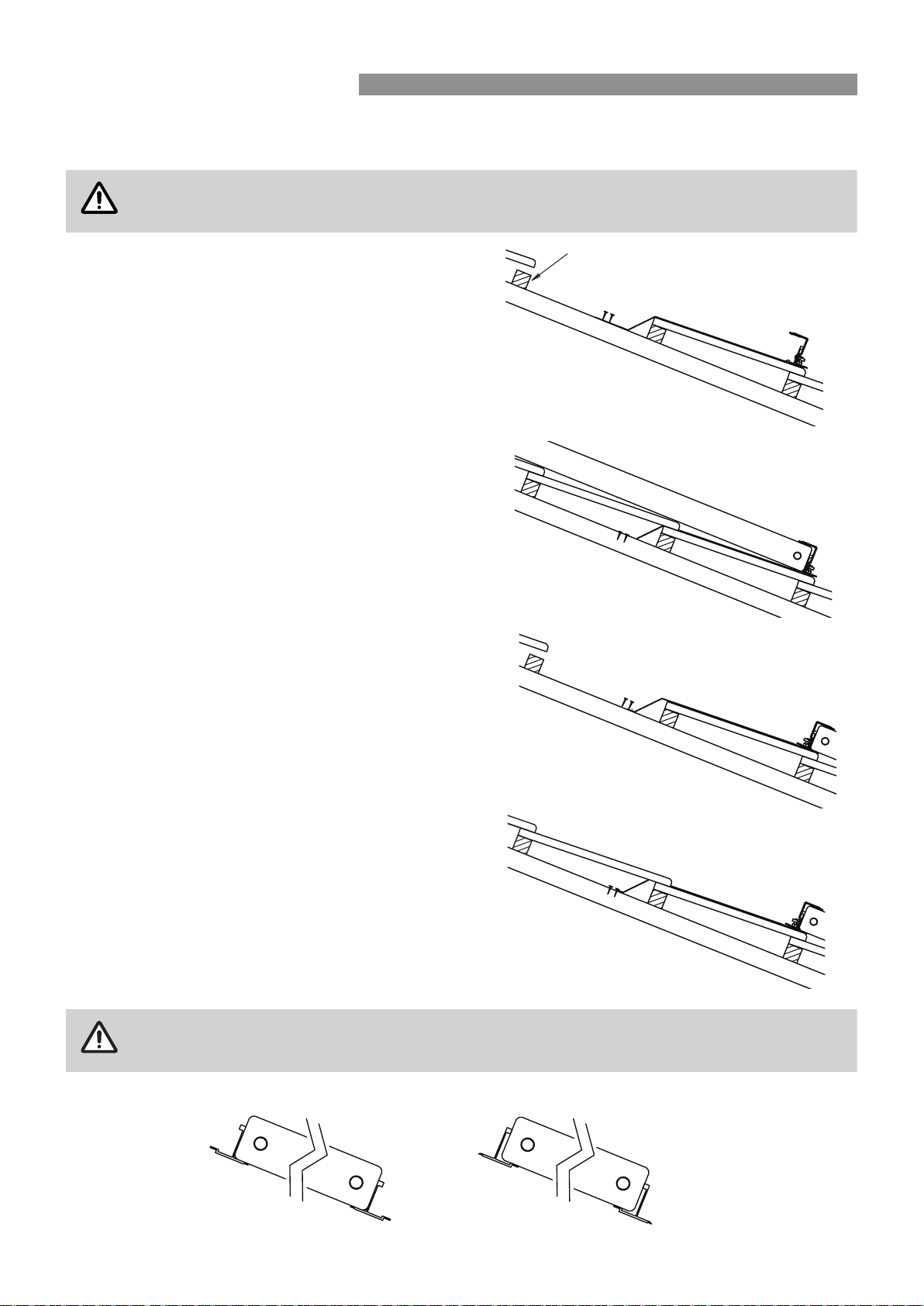
STANDARD INSTALLATION
Fastening Collectors to a Tiled Roof
WARNING
This type of installation is not suitable for use on roofs over 10 m high�
This type of installation is not suitable for use in cyclonic areas�
Fasten the collector mounting straps to the mounting rail�
Attach the collector mounting straps to the rafter or truss
under the tiles�
Nail strap to rafter
Tiles removed
Place the collector(s) onto the roof above the lower rail� If
more than one collector is being installed then join them
together using the barrel unions supplied�
Using the supplied self drilling screws, fasten the rail to
the collector, through the square holes in the rail Do
not fasten in other locations as damage to the collector
header pipe may occur� Be careful to adequately tighten
the screws to ensure the connection is secure without
stripping the threads in the collector case�
Position the upper collector rail above the collectors�
Fasten the rail to the collector, through the square holes
in the rail using the supplied self drilling screws�
Attach the collector mounting straps to the rafter or truss
under the tiles�
Nail strap
to rafter
Tiles removed
Replace the tiles and ensure the collector is secure, and
the roof is weather tight�
WARNING
Please ensure the collector rails are positioned in the correct orientation against the collector�
Rinnai 24 CC B OIM
INSTALLATION - ALL SYSTEMS
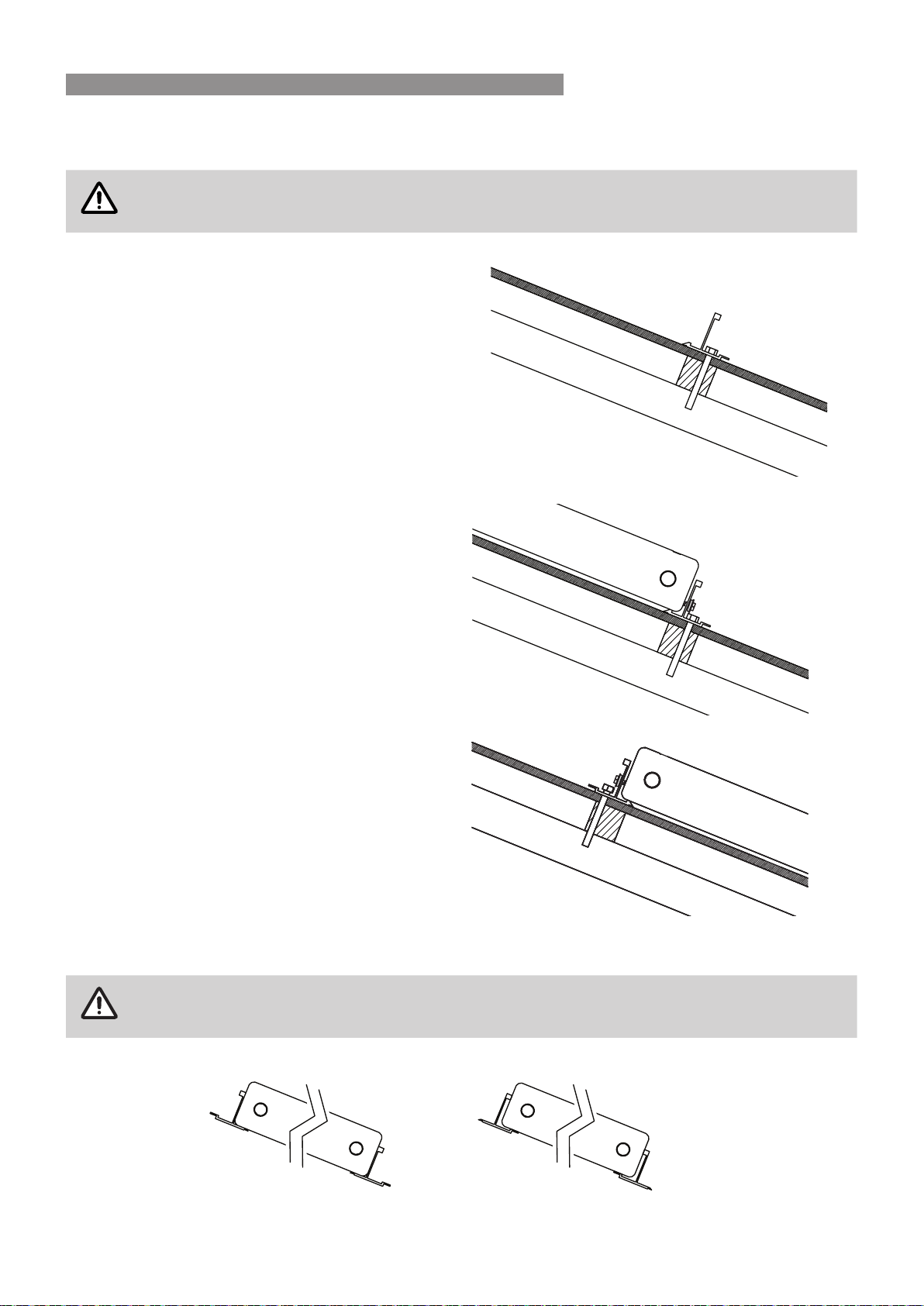
Fastening Collectors to a Metal Roof
WARNING
This type of installation is not suitable for use on roofs over 10 m high�
This type of installation is not suitable for use in cyclonic areas�
Position the lower collector mounting rail assembly so
that the rail is over the roof purlin�
Drill through the roof iron and purlin using the holes in
the rail as a guide� Apply some silicone sealant down
the holes to ensure no water leakage�
Bolt the rail to the roof purlin using a suitable fastener�
Position the collector(s) onto the roof above the lower
rail. If more than one collector is being installed, join
them together using the barrel unions supplied�
Using the supplied self drilling screws, fasten the rail to
the collector, through the square holes in the rail Do
not fasten in other locations as damage to the collector
header pipe may occur� Be careful to adequately
tighten the screws to ensure the connection is secure
without stripping the threads in the collector case�
Position the upper collector rail above the collectors�
Fasten the rail to the collector, through the square
holes in the rail using the supplied self drilling screws�
Drill through the roof iron and purlin using the upper
mounting rail as a guide� Apply some silicone sealant
down the holes to ensure no water leakage and
secure with suitable fasteners�
Alternatively the rail can be attached to the roof using
the collector mounting straps�
WARNING
Please ensure the collector rails are positioned in the correct orientation against the collector�
Rinnai 25 CC B OIM
INSTALLATION - ALL SYSTEMS
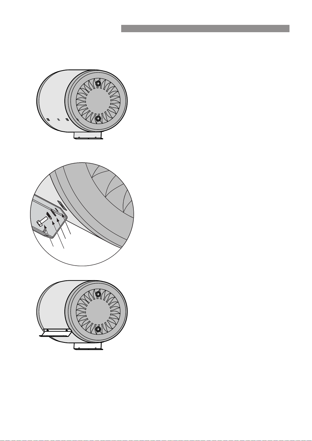
Attaching mounting rail to cylinder
Depending on the packaging, either one or two rails are attached to the cylinder�
The extra rail and fastenings are packed with the cylinder�
They are screwed into the rail mounting holes in the
cylinder�
Washer
Spring
Washer
Rail
Bolt
Attach the rail using the bolts, washers and spring washers
in the order shown�
Ensure the feet on the rails face outwards
Ensure that the bolt is tightened sufciently to atten the
spring washer� This ensures that the bolt is adequately
tightened�
Once the rail is attached and suitably tightened, continue
the cylinder installation as shown on the next page�
Rinnai 26 CC B OIM
INSTALLATION - ALL SYSTEMS
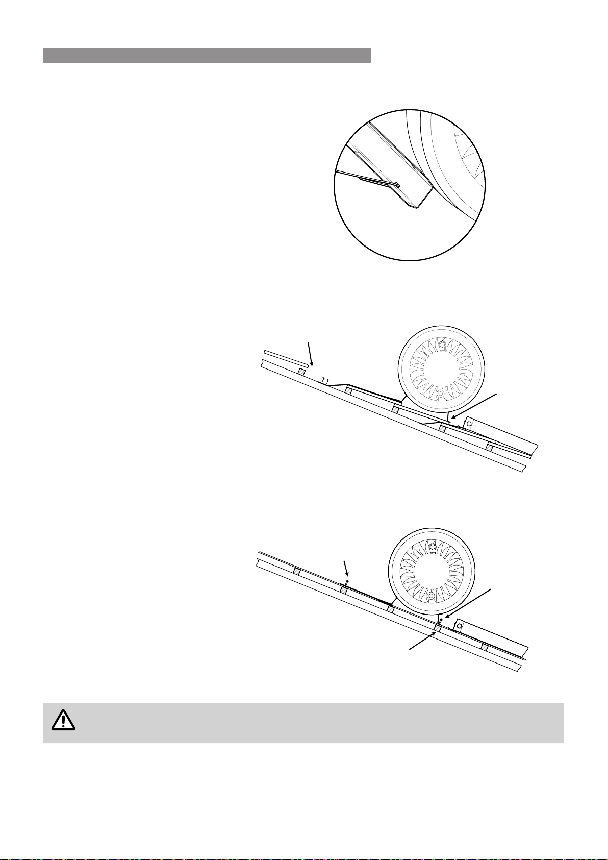
Fastening Cylinder to Roof
Lift the storage cylinder onto the roof and
locate it above the collector bank� The
cylinder’s position should be as central as
possible to the collector bank� The lower rail
must be on a load bearing surface�
Slide the cylinder support strap into the slots
located in the uppermost cylinder support
bracket so that the strap is in line with a
suitable fastening position
Tiled Roof
Remove tiles one row up from the storage
cylinder� Apply tension to the straps and attach
them to the rafters using a suitable fastener�
Replace the tiles
FASTEN STRAP
TO RAFTER
TILE
REMOVED
LOWER CYLINDER RAIL
MUST BE ON A LOAD
BEARING SURFACE
Metal Roof
Bolt the lower support rail to the roof using a
suitable fastener�
Apply tension to the cylinder support straps
and attach them to the rafters using a suitable
fastener�
Seal any holes in roof using a suitable sealant
to ensure roof is water tight�
BOLT STRAP TO ROOF USING
A SUITABLE FASTENER
BOLT RAIL TO ROOF USING
A SUITABLE FASTENER
LOWER CYLINDER RAIL MUST BE
ON A LOAD BEARING SURFACE
LOWER CYLINDER RAIL MUST BE
ON A LOAD BEARING SURFACE
NOTE
The spacing between the cylinder and the collectors can vary� The copper pipe provided in the kit may
need to be shortened to allow for this�
Rinnai 27 CC B OIM
INSTALLATION - ALL SYSTEMS
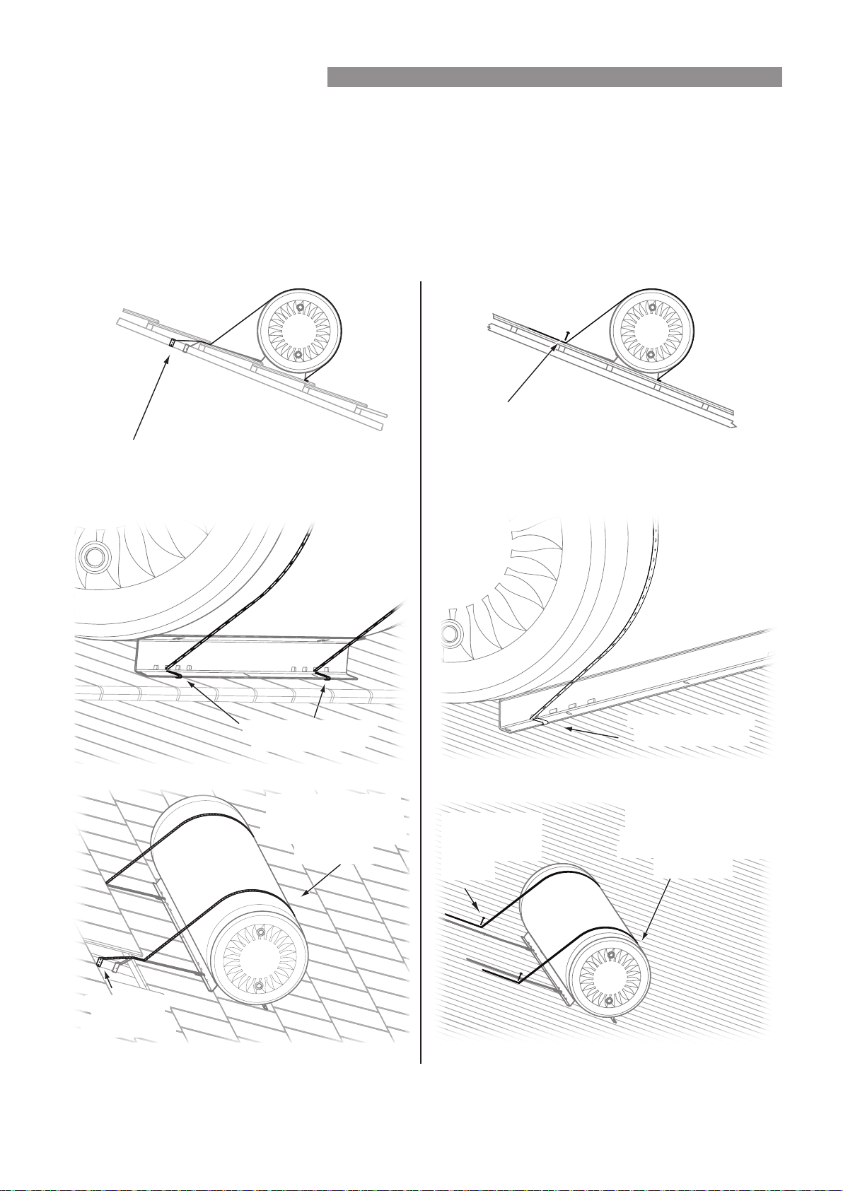
ROOF PITCH GREATER THAN 30°
In situations where a Close Coupled System is installed onto a roof with a pitch of 30° or greater, an additional strap
must be used to prevent the cylinder tipping over� Builders strapping available from hardware stores is suitable for
this� The strapping is attached through the slots in the front cylinder rail, goes over the tank and is then fastened to
the roof behind the cylinder�
Tiled Roof Metal Roof
Securely fasten
strap to roof using
a suitable fastener
Securely fasten
strap to roof using
a suitable fastener
Attach straps through
slot in cylinder rail.
Attach strap through
slot in cylinder rail.
Securely fasten
strap using a
suitable fastener
Ensure straps are on
main section of tank as
plastic endcaps are not
loadbearing
Ensure straps are on
main section of tank as
plastic endcaps are not
loadbearing
Securely fasten
straps to roof
using a suitable
fastener
Rinnai 28 CC B OIM
INSTALLATION - ALL SYSTEMS
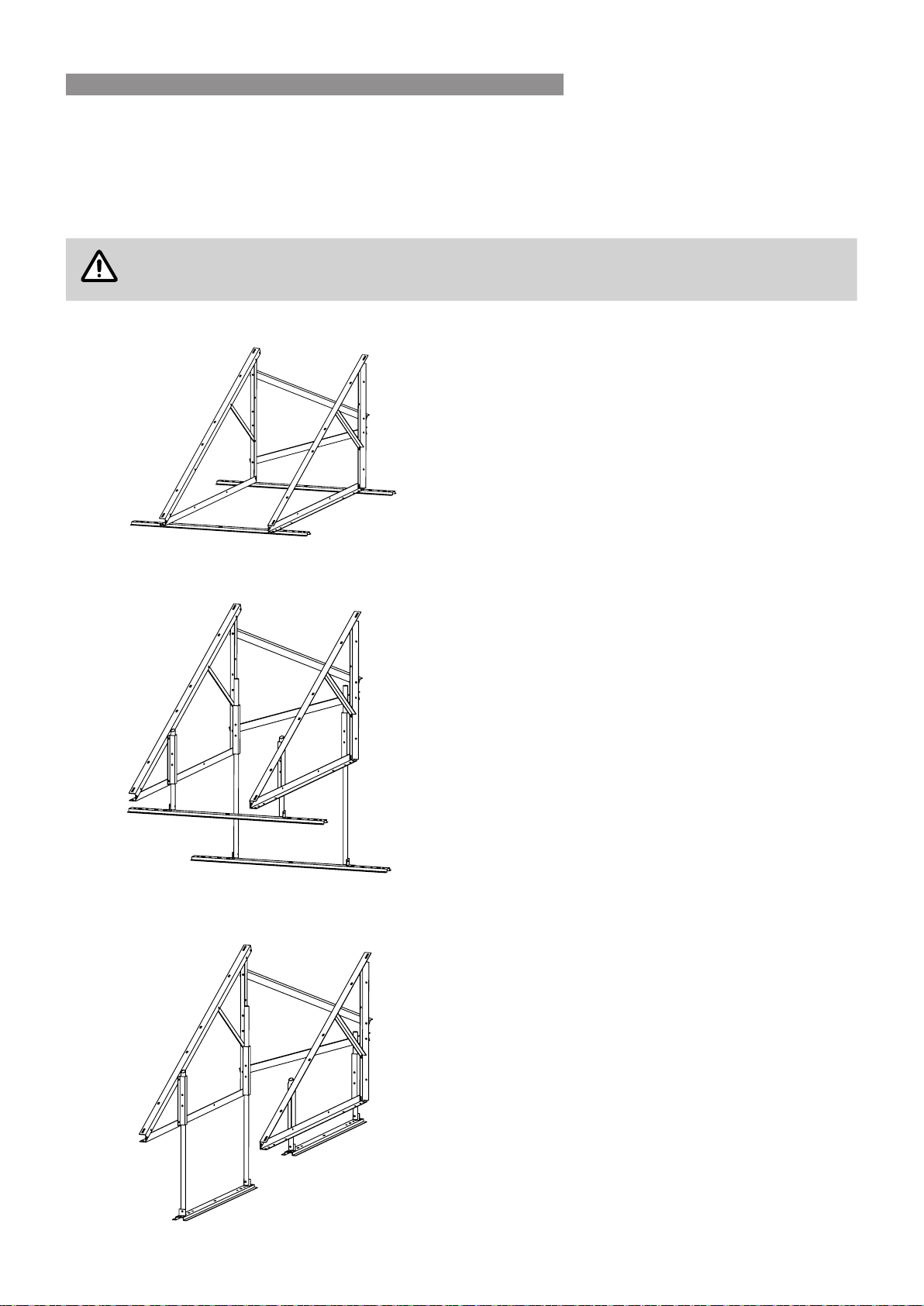
FRAMED INSTALLATIONS - CYCLONE FRAME
Assemble cyclone frame and mount components as described in instructions provide with cyclone frame kit�
FRAMED INSTALLATIONS - FLAT, REVERSE AND SIDE PITCH
WARNING
This type of installation is not suitable for use on roofs over 10 m high�
This type of installation is not suitable for use in cyclonic areas�
Flat Roof Frame
For use on a at roof or where the roof pitch is too low.
This frame allows the system to be installed at a
suitable inclination�
Installations instructions are provided in the Rinnai
Frame Installation Manual�
A Glass Lined 330 litre tank with 3 collectors
CANNOTbeinstalledonaatroofframe
Reverse Pitch Frame
These comprise of a Close Coupled system at roof
frame and a side/reverse pitch kit�
They can be used when the system need to be
installed in the reverse direction to the direction the
roof is facing�
For example, using a reverse pitch frame on a South
facing roof enables the system to be oriented to the
North�
Installations instructions are provided in the Rinnai
Frame Installation Manual�
A 330 litre tank with 3 collectors CANNOT be
installed on a reverse pitch roof frame
Side Pitch Frame
These comprise of a Close Coupled system at roof
frame and a side/reverse pitch kit�
They can be used when the system need to be
installed side on to the direction the roof is facing�
For example, using a side pitch frame on an East or
West facing roof to enables the system to be oriented
to the North�
Installations instructions are provided in the Rinnai
Frame Installation Manual�
A 330 litre tank with 3 collectors CANNOT be
installed on a side pitch roof frame
Rinnai 29 CC B OIM
INSTALLATION - ALL SYSTEMS
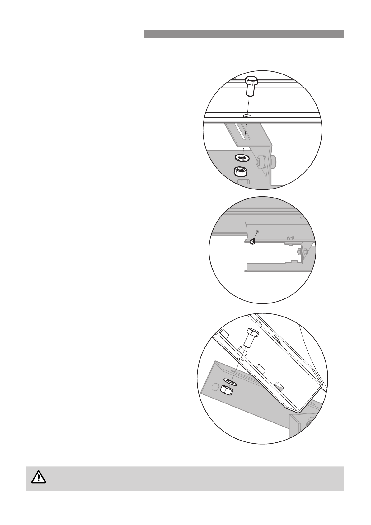
Mounting Collectors and Cylinder to Frame
Attach the lower mounting rail (provided in the
installation kit) to the frame, using the nuts bolts and
washers provided in the frame kit�
Position the collector(s) on the lower rail
For installations with 2 or 3 collectors, join the
collectors using the barrel unions provided in the
installation kit�
Fasten the collector(s) to the rail using the screws
provided in the installation kit� The screws must go
through the square holes in the rail� Do not fasten
in other locations, as damage to the collector header
pipe may occur�
Position the upper rail above the collector(s) and
fasten with the provided screws�
Position the cylinder above the collector(s) and
fasten both cylinder rails to the frame using the nuts,
bolts and washers provided in the frame kit�
NOTE
The spacing between the cylinder and the collectors can vary� The copper pipe provided in the kit may
need to be shortened to allow for this�
Rinnai 30 CC B OIM
INSTALLATION - ALL SYSTEMS
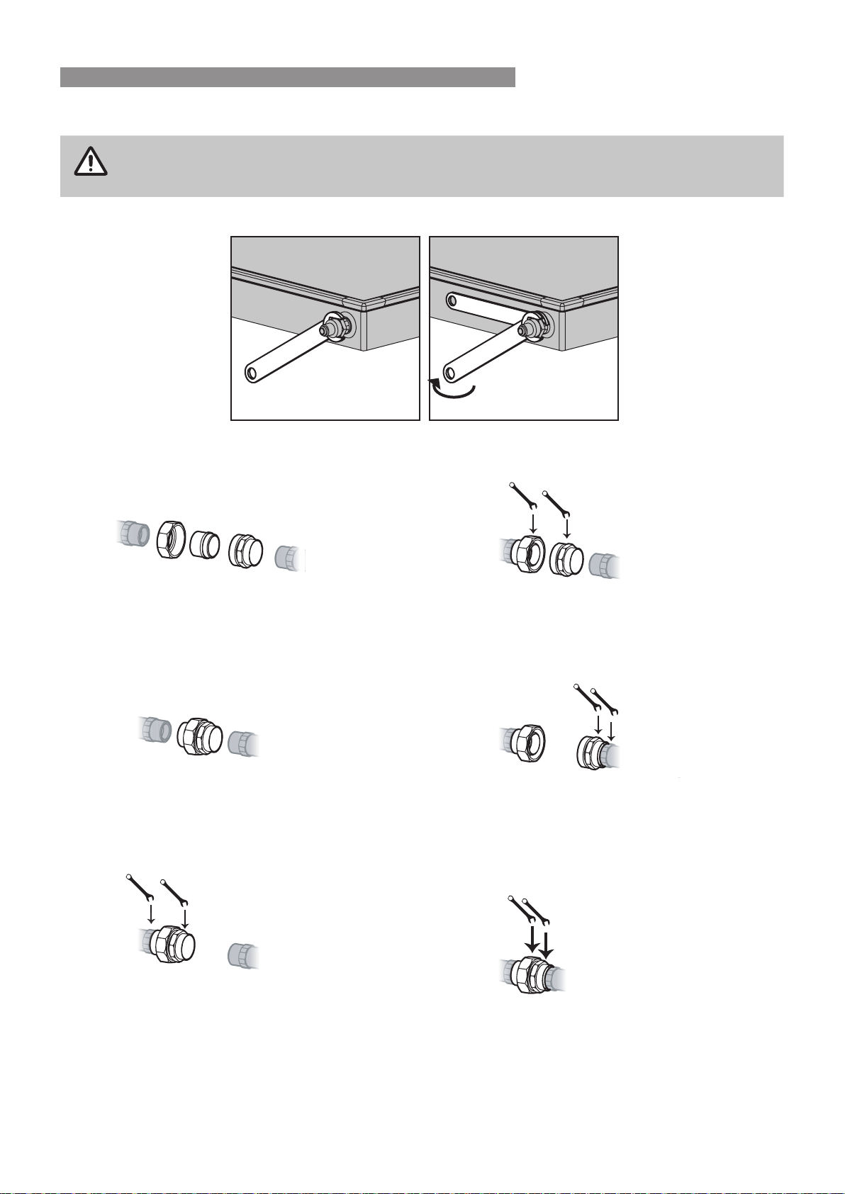
CONNECTING FITTINGS TO COLLECTOR
WARNING
When connecting ttings to collectors ensure that the ats at the end of the collector header are held
in place with one spanner, while another spanner is used to tighten tting. Collector damage or leaks
may occur if this isn't done correctly�
Connecting Barrel Unions
1.
A
B
C
Identify the 3 components of the barrel union as
A,B or C
2.
Fasten the barrel union components together�
3.
Attach the collector header to the entire barrel
union with component B screwing onto the
threaded end of the header�
Tighten with two spanners in the places indicated
in the diagram above�
4.
Separate component C from components A and
B using two spanners in the places indicated in
the diagram above�
5.
Fasten component C to the header of the 2nd
collector�
Tighten with two spanners in the places indicated
in the diagram above�
6.
Join the barrel union components together�
Tighten with two spanners in the places indicated
in the diagram above�
Rinnai 31 CC B OIM
INSTALLATION - ALL SYSTEMS
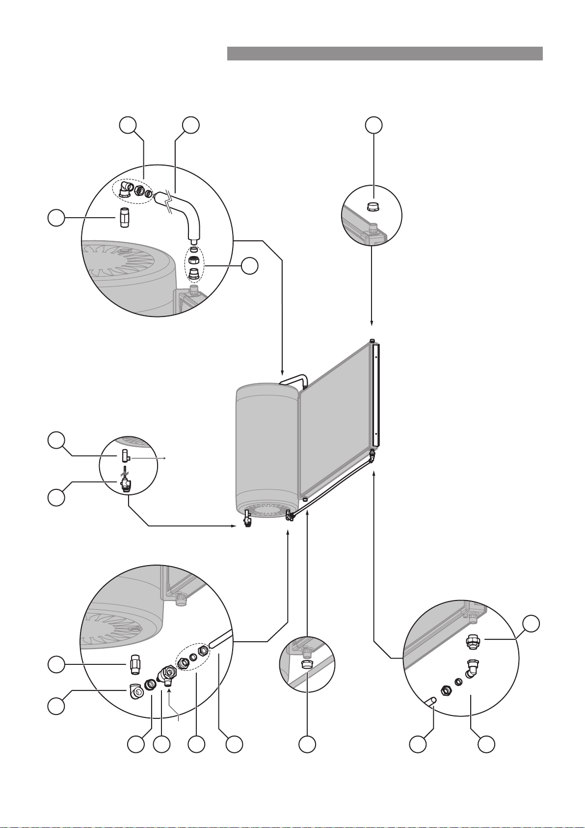
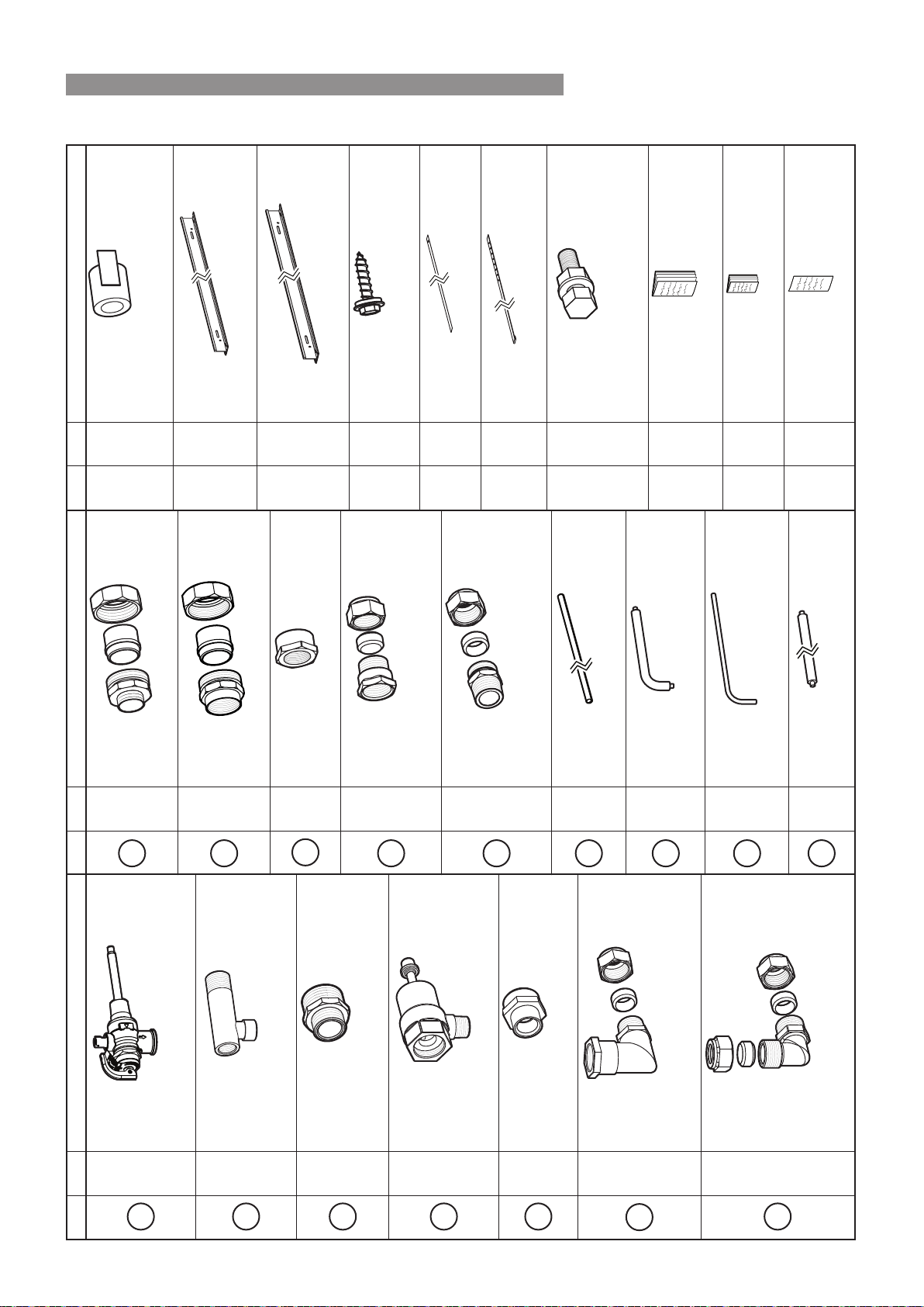
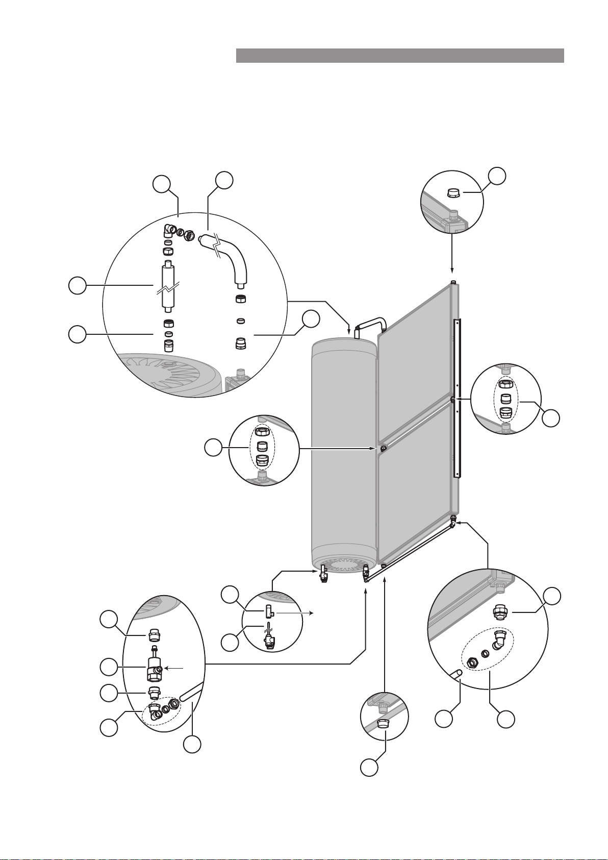
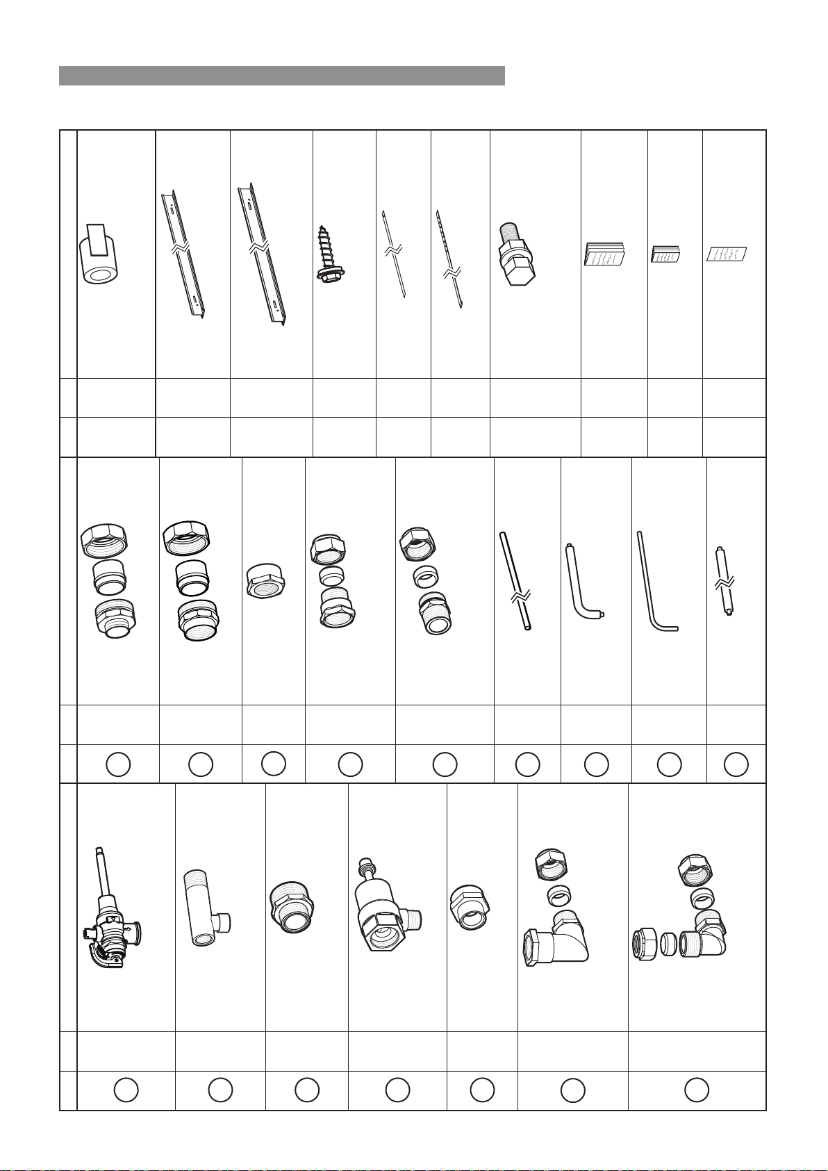
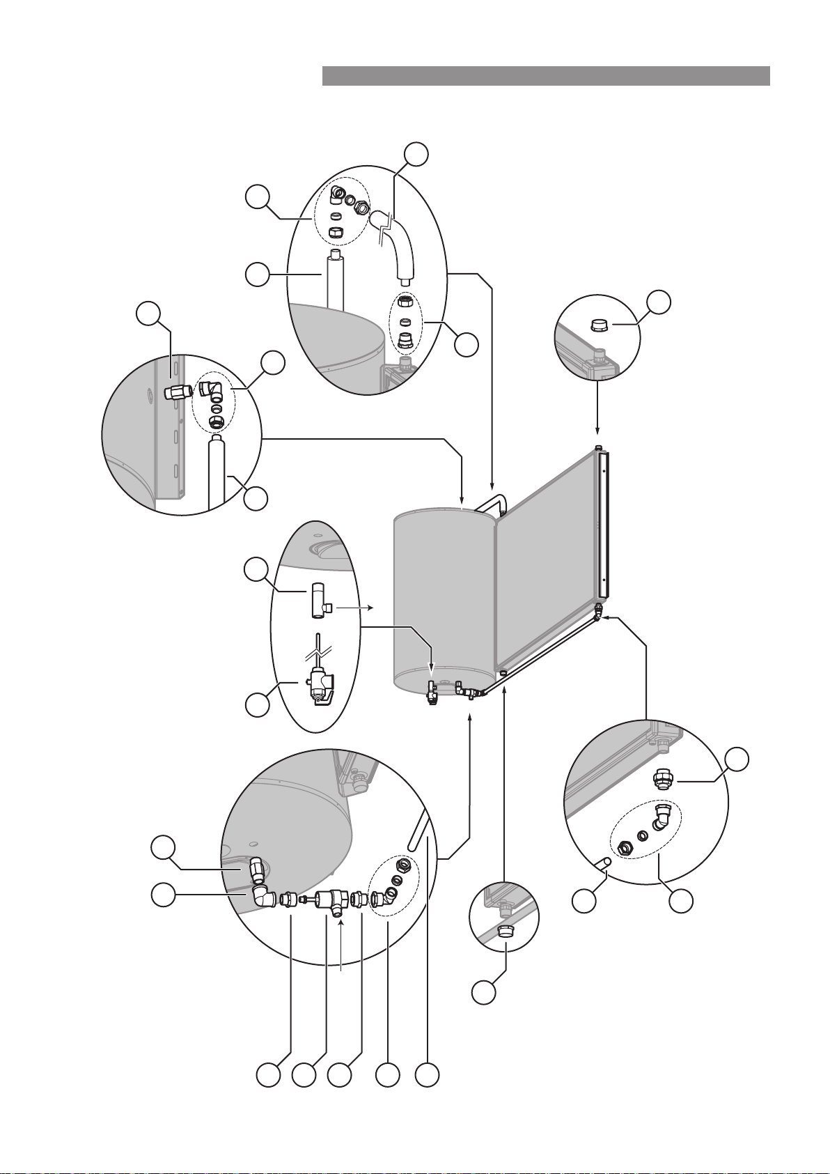
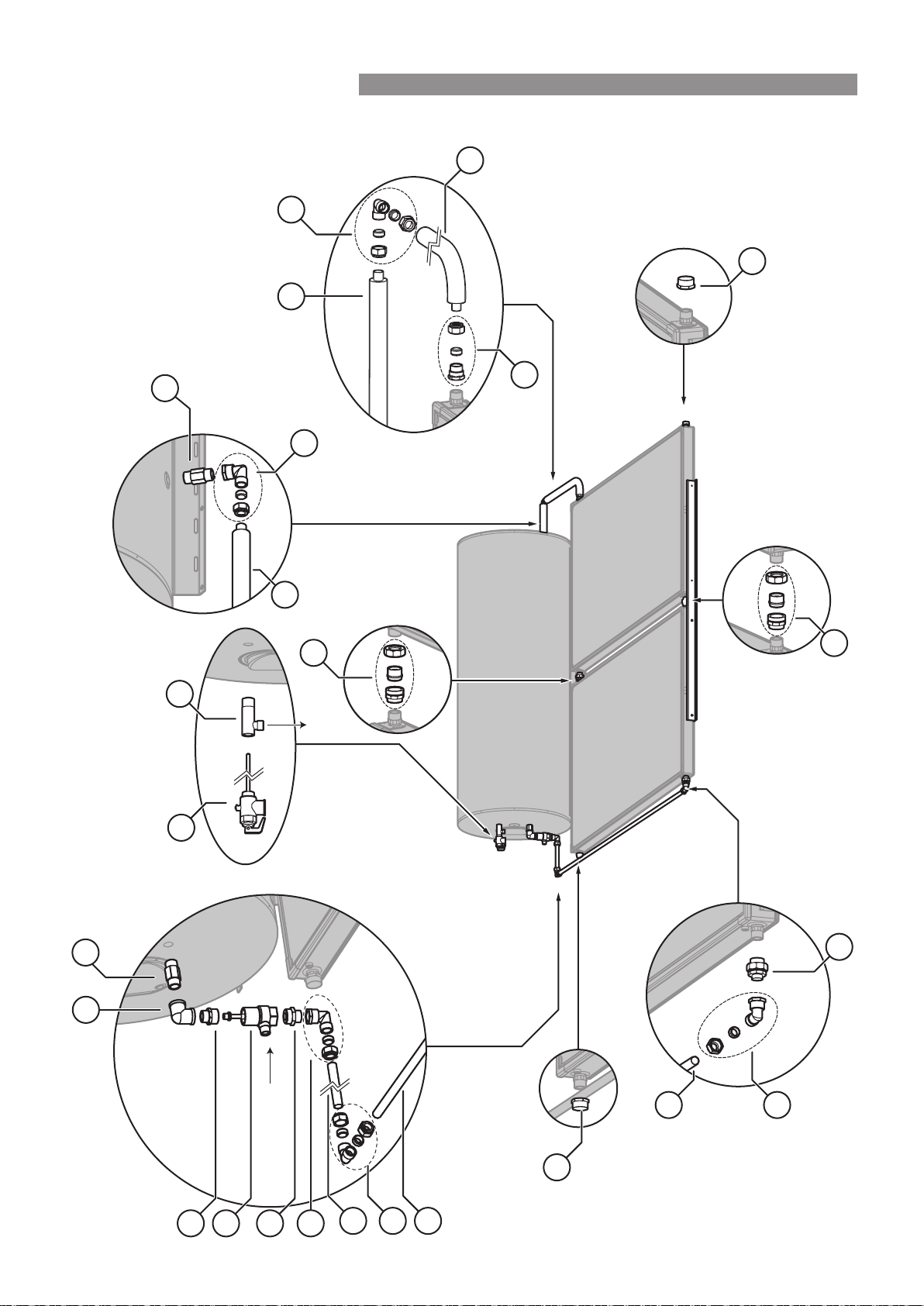
180 LITRE SS CYLINDER WITH 1 SP200B OR SP200BEX COLLECTOR - BIKS180CCT01C
The spacing between the cylinder
and the collector can vary.
The copper pipe supplied in the kit may
need to be shortened to allow for this
5
30
4
6
7
3
30
9
11
13
13
9
31
3
14
21
Cold Water Inlet
Hot Water
Outlet
Rinnai 32 CC B OIM
INSTALLATION - ALL SYSTEMS
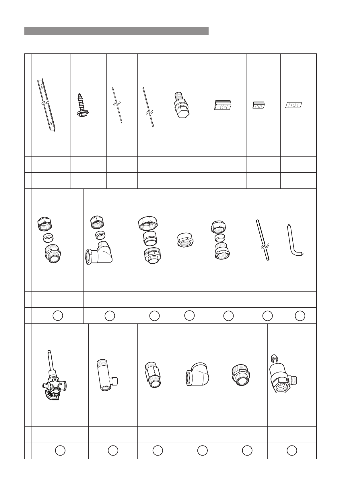
180 LITRE SS CYLINDER WITH 1 SP200B OR SP200BEX COLLECTOR - BIKS180CCT01C
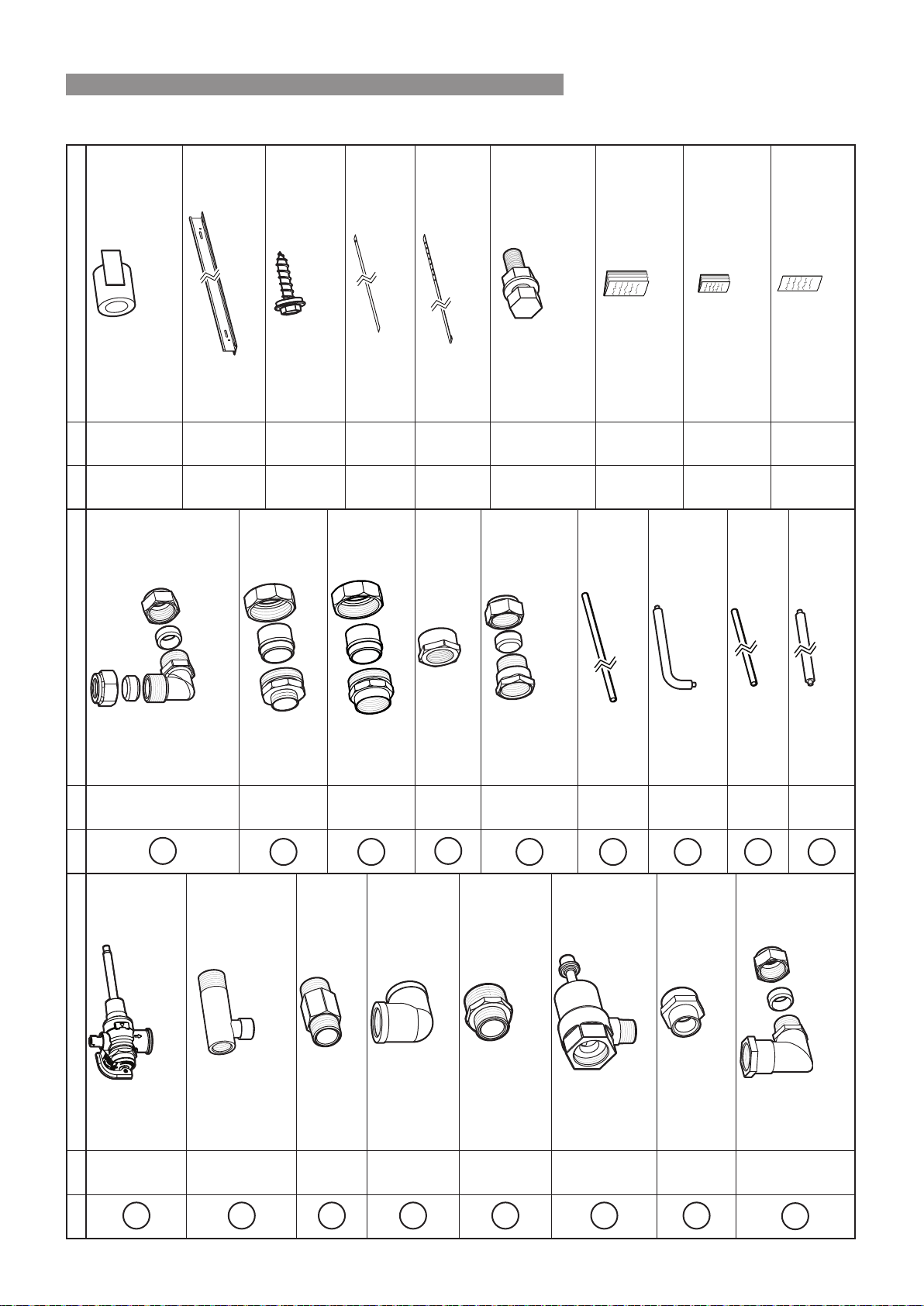
Qty Item / Part Number
1
1
P&TR Valve (850 kPa)
*supplied with cylinder 11004784
2
1
T adaptor hot outlet
*supplied with cylinder 19001018
3
2
R ¾ Nipple (long) 17201011
4
1
Elbow Rp ¾ x Rp ¾ 21201004
5
1
Reducing Nipple
R1 x R ¾ 17201036
6
1
TA Valve 11007711
Qty Item / Part Number
7
1
Adaptor Assembly Nipple 16601067
M33 x G ¾ (kinco) Nut 16801018
Olive 33001011
9
2
Elbow assembly 21201026
- Rp ¾ x G ¾ (Kinco)
- 1 x Kinco nut and olive ¾
11
1
Barrel union ¾M - ¾F 32201717
13
2
Cap 16001011
14
1
Adaptor
- 1 x adaptor Rp ¾ x G ¾ (kinco) 32201735
- 1 x Kinco nut and olive ¾
30
1
Copper Pipe 31601791
2000 mm
31
1
Insulated Copper Pipe 31601790
125 x 410 mm
Qty Item / Part Number
- 2
Mounting Rail Small (1�0 m) 14201196
- 4
Screw Self Drilling with Seal
12-11 x 25 mm 22601094
- 4
Collector Mounting Straps 12401012
- 2
Cylinder Mounting Straps 12401013
- 4
M8 Bolt Washer and Nut Bolt 22601052
(used to bolt collector mounting Washer 17401072
strap to mounting rail) Nut 16801062
- 1
Operation and Installation Manual 15401115
- 1
Warranty Booklet 15401041
- 1
STC form 15401023
Rinnai 33 CC B OIM
INSTALLATION - ALL SYSTEMS
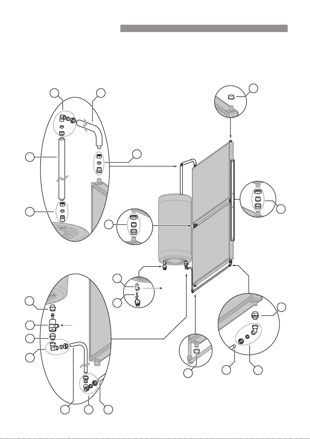
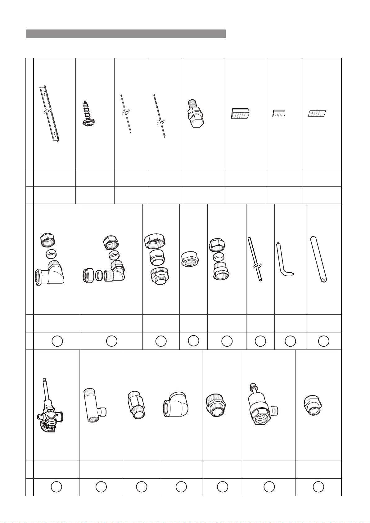
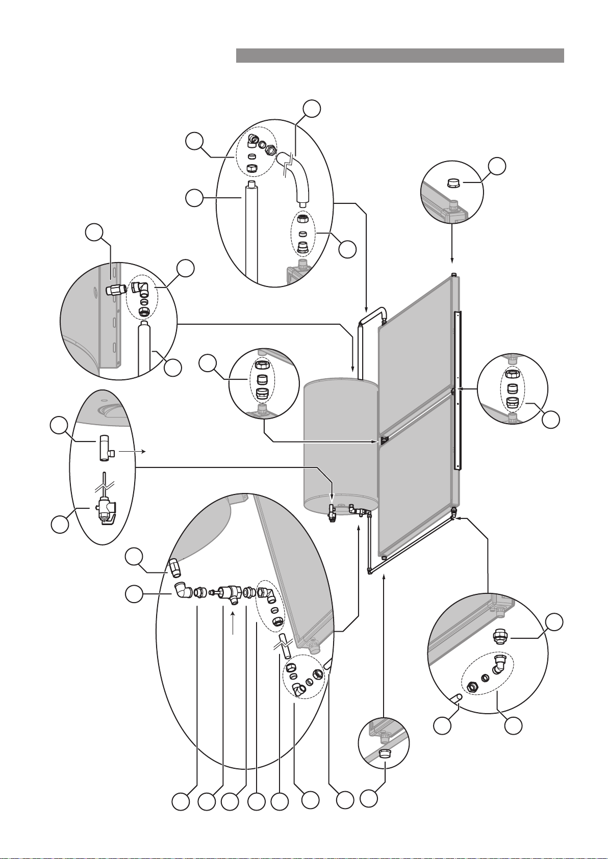
180 LITRE SS CYLINDER WITH 2 SP200B OR SP200BEX COLLECTORS - BIKSUNICCT23C
The spacing between the cylinder
and the collectors can vary.
The copper pipe supplied in the kit may
need to be shortened to allow for this
32
30
9
10
8 6
5
Cold Water
Inlet
30
9
11
13
13
12
12
10
31
14
3315
21
Hot Water
Outlet
Rinnai 34 CC B OIM
INSTALLATION - ALL SYSTEMS
180 LITRE SS CYLINDER WITH 2 SP200B OR SP200BEX COLLECTORS - BIKSUNICCT23C
Qty Item / Part Number
1
1
P&TR Valve (850 kPa)
*supplied with cylinder 11004784
2
1
T adaptor Hot Outlet
*supplied with cylinder 19001018
5
1
Reducing Nipple
R1 x R ¾ 17201036
6
1
TA Valve 11007711
8
1
Adaptor 16601096
M33 x R ¾
9
2
Elbow assembly 21201026
- Rp ¾ x G ¾ (Kinco)
- 1 x Kinco nut and olive ¾
10
2
Elbow assembly 21201038
- 1 x Elbow G ¾ (Kinco) x G ¾ (Kinco)
- 2 x Kinco nuts and olives ¾
Qty Item / Part Number
11
1
Barrel union ¾M - ¾F 32201717
12
4
Barrel union ¾F - ¾F 32201105
13
2
Cap 16001011
14
1
Adaptor
- 1 x adaptor Rp ¾ x G ¾ (kinco) 32201735
- 1 x Kinco nut and olive ¾
15
1
Adaptor
- 1 x adaptor R¾ x G ¾ (kinco) 32201713
- 1 x Kinco nut and olive ¾
30
1
Copper Pipe 31601791
2000 mm
31
1
Insulated Copper Pipe 31601790
125 x 410 mm
32
1
Copper Pipe 31601784
125 x 565 mm (Installer to cut to 125 x 445 mm)
33
1
Insulated Copper Pipe 31601794
745 mm (Installer to cut to 625 mm)
Qty Item / Part Number
- 2
Insulation and Foil Tape 33202055
For use with Barrell Unions (connecting collectors)
33202055 contains 2 x insulation and 2 x tape
- 2
Mounting Rail Medium (1�5 m) 14201197
- 2
Mounting Rail Large (2�5 m) 14201198
- 12
Screw Self Drilling with Seal
12-11 x 25 mm 22601094
- 4
Collector Mounting Straps 12401012
- 2
Cylinder Mounting Straps 12401013
- 4
M8 Bolt Washer and Nut Bolt 22601052
(used to bolt collector mounting Washer 17401072
strap to mounting rail) Nut 16801062
- 1
Operation and Installation Manual 15401115
- 1
Warranty Booklet 15401041
- 1
STC form 15401023
Rinnai 35 CC B OIM
INSTALLATION - ALL SYSTEMS
The spacing between the cylinder
and the collectors can vary.
The copper pipe supplied in the kit may
need to be shortened to allow for this
68
5
9
20
Cold Water
Inlet
20
9
11
13
13
12
12
14
31
10
15
34
21
Hot Water
Outlet
330 LITRE SS CYLINDER WITH 2 SP200B OR SP200BEX COLLECTORS - BIKS330CCT02C
Rinnai 36 CC B OIM
INSTALLATION - ALL SYSTEMS
Qty Item / Part Number
1
1
P&TR Valve (850 kPa)
*supplied with cylinder 11004784
2
1
T adaptor hot outlet
*supplied with cylinder 19001018
5
1
Reducing Nipple
R1 x R ¾ 17201036
6
1
TA Valve 11007711
8
1
Adaptor 16601096
M33 x R ¾
9
2
Elbow assembly 21201026
- Rp ¾ x G ¾ (Kinco)
- 1 x Kinco nut and olive ¾
10
1
Elbow assembly 21201038
- 1 x Elbow G ¾ (Kinco) x G ¾ (Kinco)
- 2 x Kinco nuts and olives ¾
Qty Item / Part Number
11
1
Barrel union ¾M - ¾F 32201717
12
2
Barrel union ¾F - ¾F 32201105
13
2
Cap 16001011
14
1
Adaptor
- 1 x adaptor Rp ¾ x G ¾ (kinco) 32201735
- 1 x Kinco nut and olive ¾
15
1
Adaptor
- 1 x adaptor R¾ x G ¾ (kinco) 32201713
- 1 x Kinco nut and olive ¾
20
1
Copper Pipe 31601770
2100 mm
31
1
Insulated Copper Pipe 31601790
125 x 410 mm
34
1
Insulated Copper Pipe 31601793
180 mm
Qty Item / Part Number
- 1
Insulation and Foil Tape 33202055
For use with Barrell Unions (connecting collectors)
33202055 contains 2 x insulation and 2 x tape
- 2
Mounting Rail Medium (1�5 m) 14201197
- 8
Screw Self Drilling with Seal
12-11 x 25 mm 22601094
- 4
Collector Mounting Straps 12401012
- 2
Cylinder Mounting Straps 12401013
- 4
M8 Bolt Washer and Nut Bolt 22601052
(
used to bolt collector mounting Washer 17401072
strap to mounting rail) Nut 16801062
- 1
Operation and Installation Manual 15401115
- 1
Warranty Booklet 15401041
- 1
STC form 15401023
330 LITRE SS CYLINDER WITH 2 SP200B OR SP200BEX COLLECTORS - BIKS330CCT02C
Rinnai 37 CC B OIM
INSTALLATION - ALL SYSTEMS
330 LITRE SS CYLINDER WITH 3 SP200B OR SP200BEX COLLECTORS - BIKSUNICCT23C
32
30
9
10
8 6
5
Cold Water
Inlet
30
9
11
13
13
12 12
12 12
10
31
14
3315
21
Hot Water
Outlet
The spacing between the cylinder
and the collectors can vary.
The copper pipe supplied in the kit may
need to be shortened to allow for this
Rinnai 38 CC B OIM
INSTALLATION - ALL SYSTEMS
330 LITRE SS CYLINDER WITH 3 SP200B OR SP200BEX COLLECTORS - BIKSUNICCT23C
Qty Item / Part Number
1
1
P&TR Valve (850 kPa)
*supplied with cylinder 11004784
2
1
T adaptor Hot Outlet
*supplied with cylinder 19001018
5
1
Reducing Nipple
R1 x R ¾ 17201036
6
1
TA Valve 11007711
8
1
Adaptor 16601096
M33 x R ¾
9
2
Elbow assembly 21201026
- Rp ¾ x G ¾ (Kinco)
- 1 x Kinco nut and olive ¾
10
2
Elbow assembly 21201038
- 1 x Elbow G ¾ (Kinco) x G ¾ (Kinco)
- 2 x Kinco nuts and olives ¾
Qty Item / Part Number
11
1
Barrel Union ¾M - ¾F 32201717
12
4
Barrel Union ¾F - ¾F 32201105
13
2
Cap 16001011
14
1
Adaptor
- 1 x adaptor Rp ¾ x G ¾ (kinco) 32201735
- 1 x Kinco nut and olive ¾
15
1
Adaptor
- 1 x adaptor R¾ x G ¾ (kinco) 32201713
- 1 x Kinco nut and olive ¾
30
1
Copper Pipe 31601791
2000 mm
31
1
Insulated Copper Pipe 31601790
125 x 410 mm
32
1
Copper Pipe 31601784
125 x 565 mm
33
1
Insulated Copper Pipe 31601794
745 mm
Qty Item / Part Number
- 2
Insulation and Foil Tape 33202055
For use with Barrell Unions (connecting collectors)
33202055 contains 2 x insulation and 2 x tape
- 2
Mounting Rail Medium (1�5 m) 14201197
- 2
Mounting Rail Large (2�5 m) 14201198
- 12
Screw Self Drilling with Seal
12-11 x 25 mm 22601094
- 4
Collector Mounting Straps 12401012
- 2
Cylinder Mounting Straps 12401013
- 4
M8 Bolt Washer and Nut Bolt 22601052
(used to bolt collector mounting Washer 17401072
strap to mounting rail) Nut 16801062
- 1
Operation and Installation Manual 15401115
- 1
Warranty Booklet 15401041
- 1
STC form 15401023
Rinnai 39 CC B OIM
INSTALLATION - ALL SYSTEMS
200 LITRE GLASS LINED CYLINDER WITH 1 SP200B OR SP200BEX COLLECTOR - BIKV200CCT01C
The spacing between the cylinder
and the collector can vary.
The copper pipe supplied in the kit may
need to be shortened to allow for this
6
8
5
9
20
4
3
20
9
11
13
13
21
3
9
14
21
22
10
1
2
Hot Water Outlet
Cold Water Inlet
Rinnai 40 CC B OIM
INSTALLATION - ALL SYSTEMS
200 LITRE GLASS LINED CYLINDER WITH 1 SP200B OR SP200BEX COLLECTOR - BIKV200CCT01C
Qty Item / Part Number
1
1
P&TR Valve (850 kPa)
*supplied with cylinder 92501192
2
1
T adaptor hot outlet
*supplied with cylinder 92501117
3
2
R ¾ Nipple (long) 17201011
4
1
Elbow Rp ¾ x Rp ¾ 21201004
5
1
Reducing Nipple
R1 x R ¾ 17201036
6
1
TA Valve 11007711
8
1
Adaptor 16601096
M33 x R ¾
Qty Item / Part Number
9
3
Elbow assembly 21201026
- Rp ¾ x G ¾ (Kinco)
- 1 x Kinco nut and olive ¾
10
1
Elbow assembly 21201038
- 1 x Elbow G ¾ (Kinco) x G ¾ (Kinco)
- 2 x Kinco nuts and olives ¾
11
1
Barrel union ¾M - ¾F 32201717
13
2
Cap 16001011
14
1
Adaptor
- 1 x adaptor Rp ¾ x G ¾ (kinco) 32201735
- 1 x Kinco nut and olive ¾
20
1
Copper Pipe 31601770
2100 mm
21
1
Insulated Copper Pipe 31601783
125 x 565 mm
22
1
Insulated Copper Pipe 31601782
360 mm
Qty Item / Part Number
- 2
Mounting Rail Small (1�0 m) 14201196
- 4
Screw Self Drilling with Seal
12-11 x 25 mm 22601094
- 4
Collector Mounting Straps 12401012
- 2
Cylinder Mounting Straps 12401013
- 4
M8 Bolt Washer and Nut Bolt 22601052
(used to bolt collector mounting Washer 17401072
strap to mounting rail) Nut 16801062
- 1
Operation and Installation Manual 15401115
- 1
Warranty Booklet 15401041
- 1
STC form 15401023
Rinnai 41 CC B OIM
INSTALLATION - ALL SYSTEMS
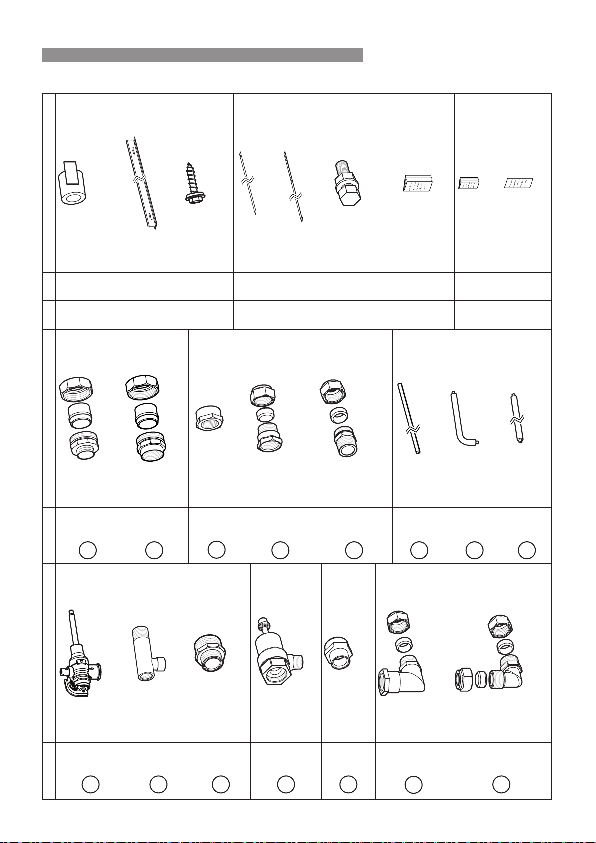
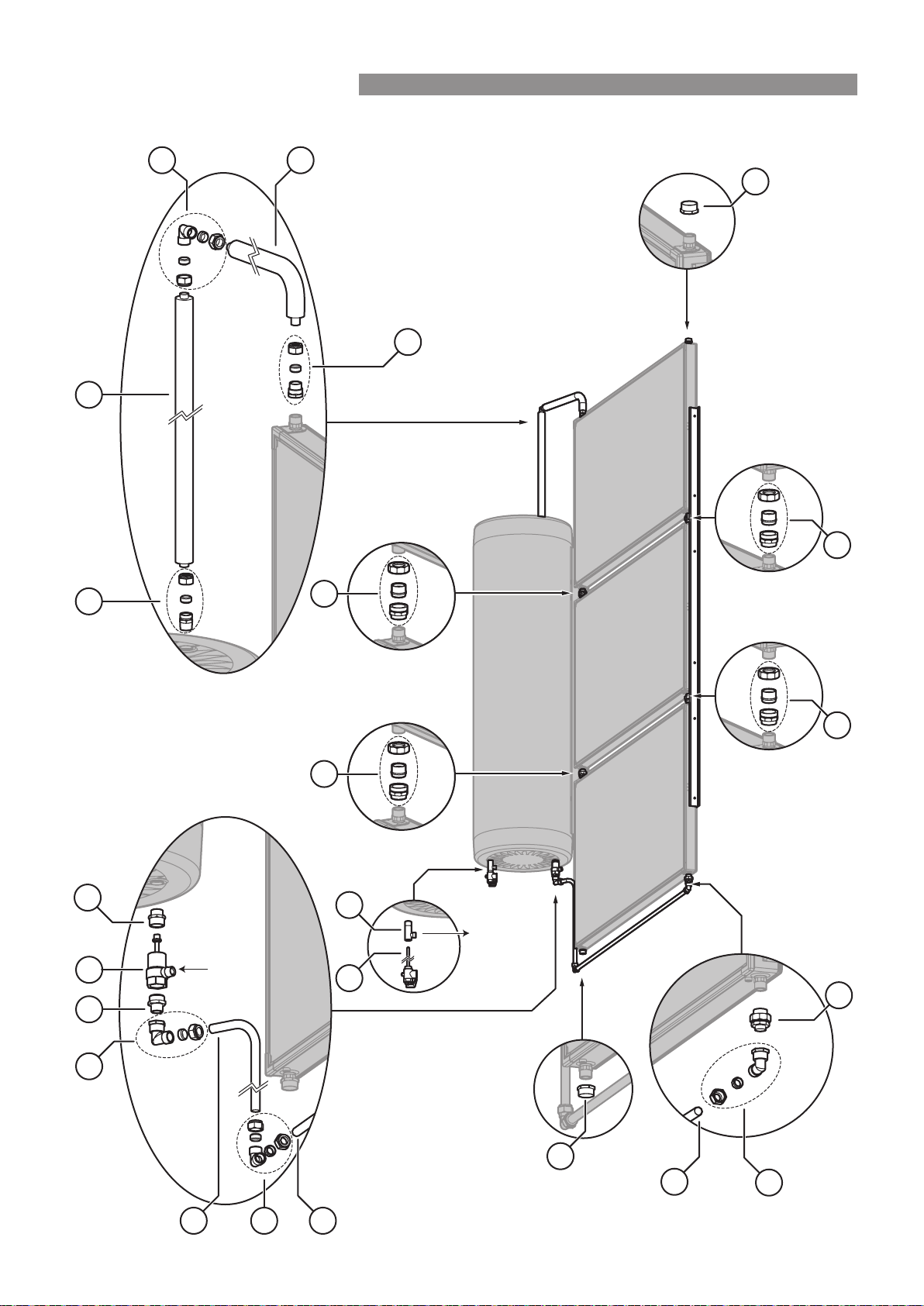
200 LITRE GLASS LINED CYLINDER WITH 2 SP200B OR SP200BEX COLLECTORS - BIKV200CCT02C
The spacing between the cylinder
and the collector(s) can vary.
The copper pipe supplied in the kit may
need to be shortened to allow for this
6
8
5
9
23
20
10
4
3
20
9
11
13
13
12
12
14
21
24
3
9
24
10
1
2
Hot
Water
Outlet
Cold Water Inlet
Rinnai 42 CC B OIM
INSTALLATION - ALL SYSTEMS
200 LITRE GLASS LINED CYLINDER WITH 2 SP200B OR SP200BEX COLLECTORS - BIKV200CCT02C
Qty Item / Part Number
1
1
P&TR Valve (850 kPa)
*supplied with cylinder 92501192
2
1
T adaptor hot outlet
*supplied with cylinder 92501117
3
2
R ¾ Nipple (long) 17201011
4
1
Elbow Rp ¾ x Rp ¾ 21201004
5
1
Reducing Nipple
R1 x R ¾ 17201036
6
1
TA Valve 11007711
8
1
Adaptor 16601096
M33 x R ¾
9
3
Elbow assembly 21201026
- Rp ¾ x G ¾ (Kinco)
- 1 x Kinco nut and olive ¾
Qty Item / Part Number
10
2
Elbow assembly 21201038
- 1 x Elbow G ¾ (Kinco) x G ¾ (Kinco)
- 2 x Kinco nuts and olives ¾
11
1
Barrel union ¾M - ¾F 32201717
12
2
Barrel union ¾F - ¾F 32201105
13
2
Cap 16001011
14
1
Adaptor
- 1 x adaptor Rp ¾ x G ¾ (kinco) 32201735
- 1 x Kinco nut and olive ¾
20
1
Copper Pipe 31601770
2100 mm
21
1
Insulated Copper Pipe 31601783
125 x 565 mm
23
1
Copper Pipe 31601785
560 mm
24
1
Insulated Copper Pipe 31601795
930 mm
Qty Item / Part Number
- 1
Insulation and Foil Tape 33202055
For use with Barrell Unions (connecting collectors)
33202055 contains 2 x insulation and 2 x tape
- 2
Mounting Rail Medium (1�5 m) 14201197
- 8
Screw Self Drilling with Seal
12-11 x 25 mm 22601094
- 4
Collector Mounting Straps 12401012
- 2
Cylinder Mounting Straps 12401013
- 4
M8 Bolt Washer and Nut Bolt 22601052
(used to bolt collector mounting Washer 17401072
strap to mounting rail) Nut 16801062
- 1
Operation and Installation Manual 15401115
- 1
Warranty Booklet 15401041
- 1
STC form 15401023
Rinnai 43 CC B OIM
INSTALLATION - ALL SYSTEMS
330 LITRE GLASS LINED CYLINDER WITH 2 SP200B OR SP200BEX COLLECTORS - BIKV330CCT02C
The spacing between the cylinder
and the collector(s) can vary.
The copper pipe supplied in the kit may
need to be shortened to allow for this
5
6
8
9
20
10
25
4
3
20
9
11
13
13
12
12
14
21
26
10
26
3
9
Hot
Water
Outlet
1
2
Cold Water Inlet
Rinnai 44 CC B OIM
INSTALLATION - ALL SYSTEMS
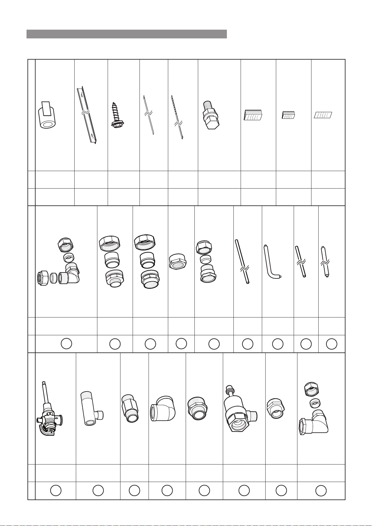
330 LITRE GLASS LINED CYLINDER WITH 2 SP200B OR SP200BEX COLLECTORS - BIKV330CCT02C
Qty Item / Part Number
1
1
P&TR Valve (850 kPa)
*supplied with cylinder 92501192
2
1
T adaptor hot outlet
*supplied with cylinder 92501117
3
2
R ¾ Nipple (long) 17201011
4
1
Elbow Rp ¾ x Rp ¾ 21201004
5
1
Reducing Nipple
R1 x R ¾ 17201036
6
1
TA Valve 11007711
8
1
Adaptor 16601096
M33 x R ¾
9
3
Elbow assembly 21201026
- Rp ¾ x G ¾ (Kinco)
- 1 x Kinco nut and olive ¾
Qty Item / Part Number
10
2
Elbow assembly 21201038
- 1 x Elbow G ¾ (Kinco) x G ¾ (Kinco)
- 2 x Kinco nuts and olives ¾
11
1
Barrel union ¾M - ¾F 32201717
12
2
Barrel union ¾F - ¾F 32201105
13
2
Cap 16001011
14
1
Adaptor
- 1 x adaptor Rp ¾ x G ¾ (kinco) 32201735
- 1 x Kinco nut and olive ¾
20
1
Copper Pipe 31601770
2100 mm
21
1
Insulated Copper Pipe 31601783
125 x 565 mm
25
1
Copper Pipe 31601787
220 mm
26
1
Insulated Copper Pipe 31601786
625 mm
Qty Item / Part Number
- 1
Insulation and Foil Tape 33202055
For use with Barrell Unions (connecting collectors)
33202055 contains 2 x insulation and 2 x tape
- 2
Mounting Rail Medium (1�5 m) 14201197
- 8
Screw Self Drilling with Seal
12-11 x 25 mm 22601094
- 4
Collector Mounting Straps 12401012
- 2
Cylinder Mounting Straps 12401013
- 4
M8 Bolt Washer and Nut Bolt 22601052
(used to bolt collector mounting Washer 17401072
strap to mounting rail) Nut 16801062
- 1
Operation and Installation Manual 15401115
- 1
Warranty Booklet 15401041
- 1
STC form 15401023
Rinnai 45 CC B OIM
INSTALLATION - ALL SYSTEMS
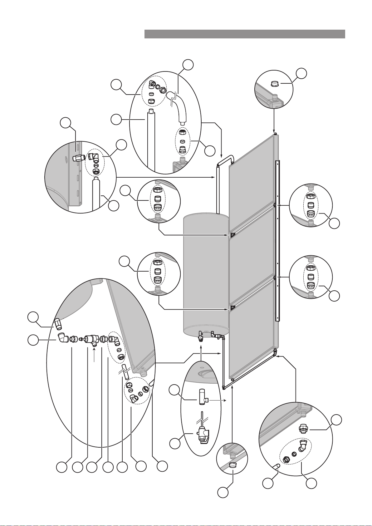
330 LITRE GLASS LINED CYLINDER WITH 3 SP200B OR SP200BEX COLLECTORS - BIKV330CCT03C
The spacing between the cylinder
and the collector(s) can vary.
The copper pipe supplied in the kit may
need to be shortened to allow for this
6
8
5
9
27
20
10
4
3
20
9
11
13
13
12 12
12
12
14
28
3
21
9
28
10
1
2
Hot Water Outlet
Cold Water Inlet
Rinnai 46 CC B OIM
INSTALLATION - ALL SYSTEMS
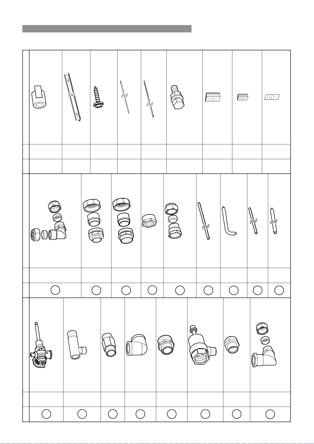
330 LITRE GLASS LINED CYLINDER WITH 3 SP200B OR SP200BEX COLLECTORS - BIKV330CCT03C
Qty Item / Part Number
1
1
P&TR Valve (850 kPa)
*supplied with cylinder 92501192
2
1
T adaptor hot outlet
*supplied with cylinder 92501117
3
2
R ¾ Nipple (long) 17201011
4
1
Elbow Rp ¾ x Rp ¾ 21201004
5
1
Reducing Nipple
R1 x R ¾ 17201036
6
1
TA Valve 11007711
8
1
Adaptor 16601096
M33 x R ¾
9
3
Elbow assembly 21201026
- Rp ¾ x G ¾ (Kinco)
- 1 x Kinco nut and olive ¾
Qty Item / Part Number
10
2
Elbow assembly 21201038
- 1 x Elbow G ¾ (Kinco) x G ¾ (Kinco)
- 2 x Kinco nuts and olives ¾
11
1
Barrel union ¾M - ¾F 32201717
12
4
Barrel union ¾F - ¾F 32201105
13
2
Cap 16001011
14
1
Adaptor
- 1 x adaptor Rp ¾ x G ¾ (kinco) 32201735
- 1 x Kinco nut and olive ¾
20
1
Copper Pipe 31601770
2100 mm
21
1
Insulated Copper Pipe 31601783
125 x 565 mm
27
1
Copper Pipe 31601789
810 mm
28
1
Insulated Copper Pipe 31601788
1180 mm
Qty Item / Part Number
- 2
Insulation and Foil Tape 33202055
For use with Barrell Unions (connecting collectors)
33202055 contains 2 x insulation and 2 x tape
- 2
Mounting Rail Large (2�5 m) 14201198
- 12
Screw Self Drilling with Seal
12-11 x 25 mm 22601094
- 4
Collector Mounting Straps 12401012
- 2
Cylinder Mounting Straps 12401013
- 4
M8 Bolt Washer and Nut Bolt 22601052
(used to bolt collector mounting Washer 17401072
strap to mounting rail) Nut 16801062
- 1
Operation and Installation Manual 15401115
- 1
Warranty Booklet 15401041
- 1
STC form 15401023
Rinnai 47 CC B OIM
INSTALLATION - ALL SYSTEMS

GAS BOOSTER LOCATION
The S20, S26 and S32 gas boosters are designed for outdoor installation only� As such, they must be located in an
above ground open air situation with natural ventilation, without stagnant areas, where gas leakage and products
of combustion are rapidly dispersed by wind and natural convection� The location must comply with the clearances
specied in AS/NZS 5601.
The gas booster must be mounted on a vertical structure with the water and gas connections on the underside
pointing downwards� The heated outlet of the cylinder is connected to cold water inlet of the gas booster�
Ensure that the wall or structure on which it is to be mounted are capable of supporting the weight of the appliance
and associated pipe work� See page 16 for individual gas booster weights� For gas boosters installed on elevated
structures or under oors specic requirements apply.
Refer to AS/NZS 5601 for details�
•
Attach the gas booster to the wall using screws�
•
Location of the gas booster ue terminal must be in accordance with Figure 6.2 of AS/NZS 5601.
If an internal model which has been converted to a solar gas booster follow information supplied with the unit for
location, mounting and ueing requirements.
GAS SUPPLY
The maximum gas consumption of the gas booster and the required gas pressure are shown on the appliance data
plate. If the gas pipe sizing is insufcient the customer will not get the full performance benet.
Gas pipe sizing must consider the gas input to the gas booster as well as all the other gas appliances on the
premises. The gas meter and regulator must be specied for this gas rate. An approved sizing chart such as the
one in AS/NZS 5601 should be used�
An approved full ow isolation valve and disconnection union must be tted to the gas supply inlet of the gas
booster. Isolation valves must not be tted directly to the booster.
HOT WATER DELIVERY TEMPERATURE
Gas boosters for use in solar hot water systems are preset to deliver a xed temperature of 70°C in accordance with
plumbing regulations� In addition, they contain the warning stating “Rinnai Water Controllers are NOT compatible
with solar hot water installations and MUST NOT BE USED in the vicinity of the temperature controller connections
inside the appliance�”
NOTE
Gas Boosters other than models designated “S20”, “S26”, “S26i”, “S32” or “Solar” must not be used�
Gas Boosters marked with the text: “THIS APPLIANCE DELIVERS WATER NOT EXCEEDING 50°C
IN ACCORDANCE WITH AS 3498” are incompatible with solar hot water systems and must not be
used�
SMARTSTART®
The Smartstart® is a separate system that works in conjunction with the Rinnai solar hot water system.
When activated by the manual activation switch, water in the pipework connected between the solar hot water
system and the hot water outlets is warmed before any outlets are opened� This results in water savings and added
convenience� Refer to page 49 for installation details�
Rinnai 48 CC B OIM
INSTALLATION - GAS BOOSTED SYSTEMS
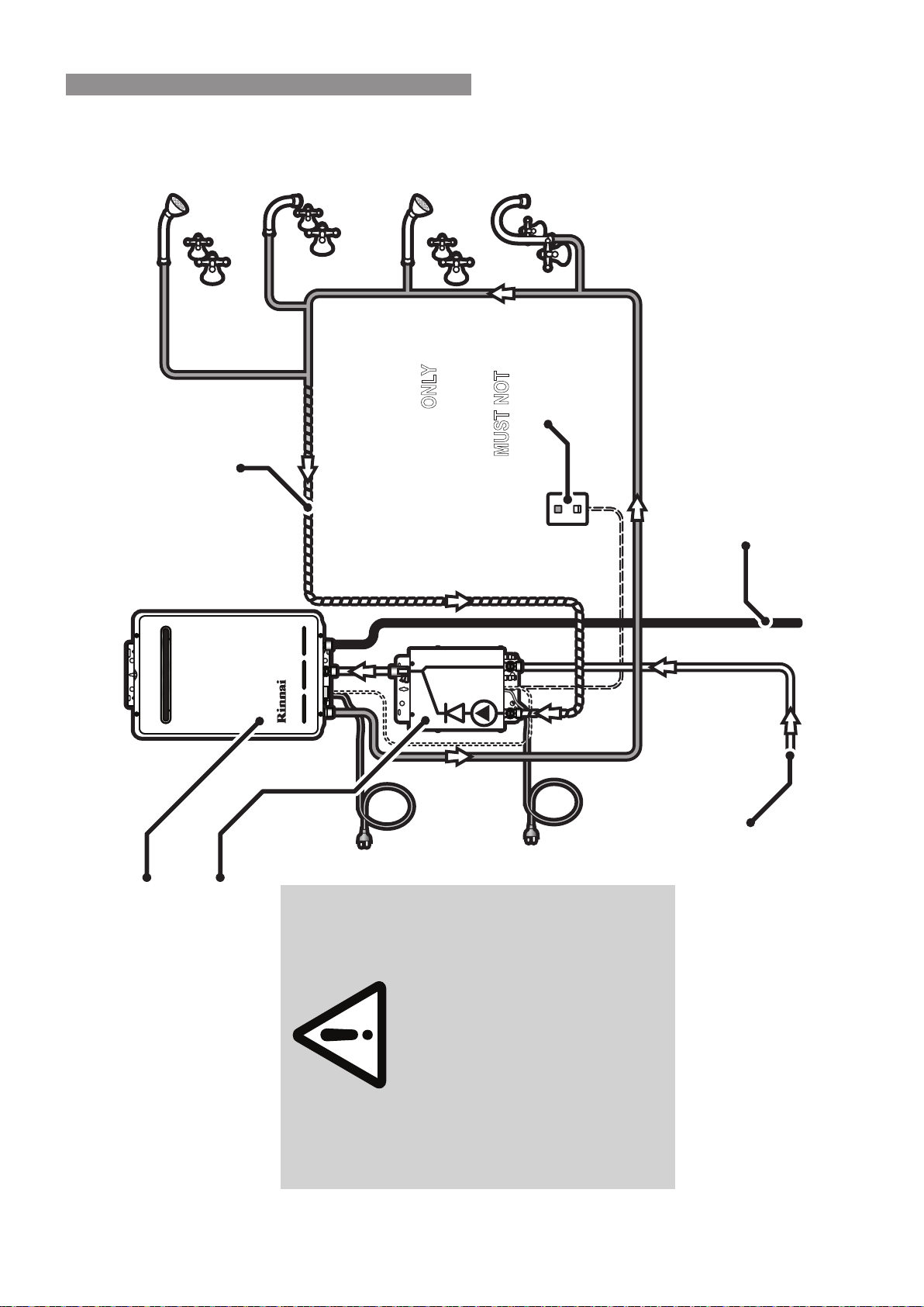
SYSTEM USING RINNAI SMARTSTART
Rinnai Smartstart Unit
Rinnai Continuous Flow Water
Heater - Gas Booster
Manual Activation
Switch ONLY
(not supplied)
Water controllers
MUST NOT
be used!
Gas Supply
Return Line
Outlets to Personal Hygiene areas
to be tempered to 50°C as per
AS/NZS 3500.4
Refer to Rinnai manuals supplied
with appliances for important
installation information.
Installations MUST conform to local
regulataions.
Supply from solar storage cylinder
IMPORTANT
Rinnai 49 CC B OIM
INSTALLATION - GAS BOOSTED SYSTEMS
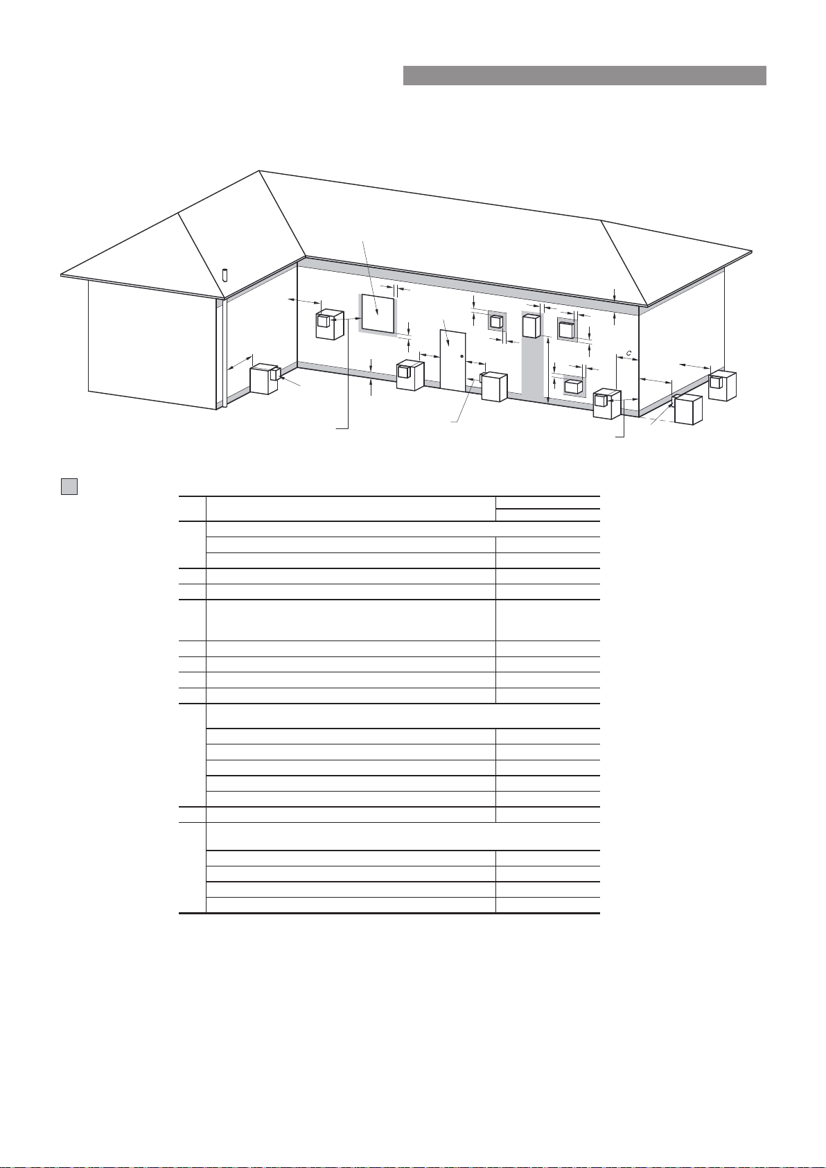
GAS BOOSTER CLEARANCES
Figure 6�2 from AS/NZS5601 is reproduced below� It was current at the time of printing, but may have been
superseded� It is the installer’s responsibility to ensure that current requirements are met�
Shading indicates prohibited ar ea for ue terminals
= Flue terminal
T= Gas meterM
= Mechanical air inlet
I
= Electricity meter or fuse box
P
= Fan-assisted appliance only
Z
Direction of
discharg e
See Note 1
See Note 1
Opening into
a building
T
T
T
T
T
T
C
M
d
d
e
e
h
j
j
j
n
b
f
a
h
P
Z
k
k
g
g
I
T
Door
Fan assisted
• Appliances 002tupni h/JM 05 ot pu
• Appliances 003tupni h/JM 05 revo
b 003* ecafrus rehto ro ynoclab a evoba ,dnuorg eht morF
c 003* renroc lanretxe ro llaw nruter a morF
d
From a gas meter (M) (see Note 5)
(see Clauses 5.11.5.9 for vent terminal location of regulator)
(See Table 6.7 for New Zealand requirements)
1000
e From an electricity meter 005)5 etoN ees( † )P( xob esuf ro
f 57epip lios ro epip niard a morF
g Horizontally from any building structure* or obstruction facing a terminal 500
h From any other flue terminal 003* ekatni ria noitsubmoc ro ,lwoc ,
• Appliances 003* tupni h/JM 051 ot pu
• Appliances 003* tupni h/JM 002 ot pu tupni h/JM 051 revo
• Appliances 005* tupni h/JM 052 ot pu tupni h/JM 002 revo
• Appliances 0051*
tupni h/JM 052 revo
• All fan-assisted flue appliances 0051egrahcsid fo noitcerid eht ni ,
k 0001rewolb aps a gnidulcni ,telni ria lacinahcem a morF
051tupni h/JM 05 ot pu sretaeh ecapS •
• Other appliances 005tupni h/JM 05 ot pu
• Appliances 0001tupni h/JM 051 ot pu dna tupni h/JM 05 revo
• Appliances 0051tupni h/JM 051 revo
1
2
See Clause 6.9.4 for restrictions on a flue terminal
under a covered area.
3
4
5
Minimum clearances d and e also apply to any combustion air intake openings of appliances.
metI.feR
a
Min. clearances (mm)
Below eaves, balconies and other projections:
j
Horizontally from an openable window, door, non-mechanical air inlet, or any other opening into a building
with the exception of sub-floor ventilation:
Vertically below an openable window, non-mechanical air inlet, or any other opening into a building with
the exception of sub-floor ventilation:
NOTES:
† - P
rohibited area below electricity meter or fuse box extends to ground level.
FIGURE 6.2 (in-part) LOCATION OF FLUE TERMINALS OF BALANCED FLUE,
ROOM SEALED, FAN-ASSISTED OR OUTDOOR APPLIANCES
* - unless appliance is certified for closer installation.
n
Where dimensions c, j or k cannot be achieved an equivalent horizontal distance measured diagonally
from the nearest discharge point of the terminal to the opening may be deemed by the Technical
Regulator to comply.
See Figure J3 for clearances required from a flue terminal to an LP Gas cylinder. A flue terminal is
considered to be a source of ignition.
For appliance s not addressed above acceptance should be obtained from the Technical Regulator.
Rinnai 50 CC B OIM
INSTALLATION - GAS BOOSTED SYSTEMS

INSTALLATION PROCEDURE
1. Install Solar Collectors and cylinders
Position and install the solar collectors and cylinder in accordance with the section ‘Standard Installation’ on
page 24� or the section ’Framed Installations’ on page 29�
2. Connect PTR Valve
Connect the PTR Valve in the location shown in the relevant diagram on pages 32 to 47� Leave the valve
outlet pointing down. Tighten the valve using the spanner ats - never use the valve body.
The PTR Valve must be adequate for the thermal loading applied to the storage cylinder� In the case of gas
boosted systems, the thermal load is applied only by the solar collectors. The continuous ow hot water
heater does not apply thermal load to the storage cylinder� The potential solar output for the solar collectors
at PTR Valve relief conditions is listed on page 15�
The PTR Valve pressure ratings vary according the cylinder specications. The maximum heater input rating
is 10�0 kW� The PTR valve rating MUST EXCEED the total input from the solar collectors� If it does not, the
PTR valve MUST be exchanged for a model of higher capacity�
For example, for a gas boosted solar system with 3 x SP200B collectors, the thermal load is 3 x 1�25 = 3�75
kW. This is less than 10.0 kW, hence the supplied PTR valve is of sufcient capacity.
Use Teon thread tape on the valve, never use hemp or other sealing materials. Ensure the tape does not
protrude past the end of the thread, which could result in it hanging over the end of the thread and blocking
the water passage through the valve�
3. Mount Gas Booster
Mount the gas booster in accordance with the section ‘Gas Booster Location’ on page 48�
4. Connect Water to Gas Booster
Connect the outlet of the storage cylinder to the water inlet of the gas booster�
5. Connect Fittings
Connect ttings and pipe work as shown in the relevant diagram on pages 32 to 47�
6. Cold Water Supply
Connect cold water supply to the T/A valve inlet. Ensure that the relevant valves are tted as described inthe
section ‘Valves and Fittings’ on page 19�
Purge the cold water supply lines to remove air and swarf before nal connection.
7. Relief Drain Lines
Independent 15 mm copper pipes must be tted to the drain outlets of the PTR and ECV. Each pipe must
be open to atmosphere and run with a continual downward grade in a frost free environment to a visible
discharge point� Drain lines must not exceed 9 metres in length�
Valves or other restrictions must not be placed in the relief valve drain outlet line�
NOTE
Some water will drip from the drain lines during heating of the water in the storage cylinder� It is
recommended to discharge directly above a drain�
8. Hot Water Discharge
Connect the hot water outlet of the gas booster to the pipe work supplying hot water to the premises�
WARNING
A temperature limiting device may be required as detailed in the section ‘Hot Water Delivery
Temperature’ on page 19�
Rinnai 51 CC B OIM
INSTALLATION - GAS BOOSTED SYSTEMS

9. Connect Gas to Booster
Connect a suitable gas supply and isolating valve to the gas booster� Follow instructions supplied with gas
booster� Keep gas booster isolated at this stage�
FILLING THE SYSTEM
CAUTION
Ensure building occupants are warned to stay clear of the solar system components, building perimeter
and roof since hot water or steam may be discharged from pipes or components�
1� Ensure the gas supply to the continuous ow water heater is isolated.
2� Turn ‘ON’ the hot water tap at the sink� Open the stop cock in the cold water mains supply line�
3� The entire system will now be lled with cold water. Most air will be dispelled through the tap. Some air needs
to be bled from the air bleed valve on the collectors�
4� Turn ‘OFF’ the hot tap at the sink when water ows freely without air bubbles or air bursts. Check all connections
for leakage and tighten if necessary. This applies especially to ttings in positions not easily accessed such
as near the solar collectors� Operate the easing gear of both the PTR and ECV valves at the storage cylinder
to ensure these valves are functional�
CAUTION
If leaks are detected the system must be drained and leaks repaired before the system is relled. If
this is necessary, cover the solar collectors with packaging cardboard or a tarp to prevent them from
heating which could result in steam or hot water being discharged from ttings..
PRE SOLAR HEATING CHECKS
Before commencing solar heating of the water in the system ensure the following actions have been completed:
Solar Collectors and Cylinder
1� Are the solar collectors installed with the correct slope and orientation to the sun?
2� Is the installation nished neatly with the roof made good, all tiles and ashings in place?
3� Are the bolts tight on the roof framework?
4� Are all solar collector and cylinder straps tted and correctly anchored to the roof structure?
5� If leak testing completed and successful, have any covers been removed from the solar collectors?
Gas Booster
1� Ensure the gas supply is isolated� Remove the test point screw located on the gas inlet connection and attach
a pressure gauge�
2� Turn on the electrical power to the gas booster and turn on the gas supply�
3� Ensure the cold water inlet (‘trio’) valve on the storage cylinder inlet is open� Open all available hot water taps�
4� Operate ALL other gas appliances at their maximum gas rate, in accordance with manufacturers instructions�
CAUTION
Ensure building occupants do not have access to hot water outlets during this procedure�
5� With all gas appliances in operation at the maximum gas rate, the pressure should read between 1�13 - 3�0
kPa on Natural Gas� On LPG the pressure should be 2�75 - 3�0 kPa� If the pressure is lower, the gas supply
is inadequate and the appliance will not operate to specication.
It is the installers responsibility to check the gas meter, service regulator and pipe work for correct operation/
sizing & rectify as required� Note that the gas regulator on the appliance is electronically controlled and factory
pre-set. Under normal circumstances it DOES NOT need adjustment during installation. Make adjustments
only if the gas booster is not operating correctly and all other possible causes for incorrect operation have
been eliminated� Instructions for gas pressure setting are located in the pocket behind the front cover of the
gas booster�
Rinnai 52 CC B OIM
INSTALLATION - GAS BOOSTED SYSTEMS

6� Close the hot water taps including the shower�
7� Close the cold water inlet (‘trio’) valve on the storage cylinder inlet and inspect and clean the strainer� Repeat
for the strainer connected at the inlet of the gas booster� This procedure may need to be repeated to ensure
the strainers remains clear, especially on new installations�
8� Conrm the hot water delivery temperature from the gas booster. This is done by checking the hot water
delivery temperature at an untempered outlet close to the water heater� This is usually the hot water outlet in
the kitchen� The untempered hot water delivery should be between 65°C & 70°C�
Temperature Limiting Devices
1� Commission any temperature limiting devices in accordance with the instructions supplied by the manufacturer�
2� Conrm the hot water delivery temperature at a tempered water outlet. Tempered water outlets should be
those supplying areas primarily used for the purposes of personal hygiene such as bathrooms� The hot
water delivery temperature should not exceed 50°C or 45°C as detailed in the section ‘Hot Water Delivery
Temperature’ on page 19�
SOLAR HEATING
1� Remove any cardboard or tarp covers that may have been placed over the solar collectors to prevent them
from heating water during installation and commissioning� Solar heating of the water in the cylinder will now
commence when sufcient solar radiation is available.
2� Activate electrical power to both the gas booster�
FINISHING THE INSTALLATION
1� After testing is completed explain to the householder the functions and operation of solar water heater
components and the importance of carrying out Maintenance as per separate warranty document�
2� Complete the installation record at the back of the manual�
3� Leave this manual and the warranty booklet with the householder�
DRAINING INSTRUCTIONS
1� The power supply to the gas booster must be switched off�
2� Close the cold water mains supply stop cock�
3� Open a hot tap to relieve pressure�
4� Disconnect the cold water connection to the Thermo-arrest (T/A) valve�
5� Remove the brass plug on the bottom right hand side of the collector bank�
6� Disconnect the ‘water inlet’ and ‘water outlet’ connections at the gas booster�
7� The system will now drain all water�
Rinnai 53 CC B OIM
INSTALLATION - GAS BOOSTED SYSTEMS

Rinnai 54 CC B OIM
INSTALLATION PROCEDURE
1. Install Solar Collectors and Cylinders
Position and install the solar collectors and cylinder in accordance with the section ‘Standard Installation’ on
page 24� or the section ’Framed Installations’ on page 29�
2. Connect PTR Valve
Connect the PTR Valve in the location shown in the relevant diagram of pages 32 to 47� Leave the valve
outlet pointing down. Tighten the valve using the spanner ats - never use the valve body.
The PTR Valve must be adequate for the thermal loading applied to the storage cylinder� In the case of gas
boosted systems, the thermal load is applied only by the solar collectors. The continuous ow hot water
heater does not apply thermal load to the storage cylinder� The potential solar output for the solar collectors
at PTR Valve relief conditions is listed in page 15�
The PTR Valve pressure ratings vary according the cylinder specications. The maximum heater input rating
is 10�0 kW� The PTR valve rating MUST EXCEED the total input from the solar collectors� If it does not, the
PTR valve MUST be exchanged for a model of higher capacity�
For example, for a gas boosted solar system with 3 x SP200B collectors, the thermal load is 3 x 1�25 = 3�75
kW. This is less than 10.0 kW, hence the supplied PTR valve is of sufcient capacity.
Use Teon thread tape on the valve, never use hemp or other sealing materials. Ensure the tape does not
protrude past the end of the thread, which could result in it hanging over the end of the thread and blocking
the water passage through the valve�
3. Connect Fittings
Connect ttings and pipe work as shown in the relevant diagram on pages 32 to 47�
4. Cold Water Supply
Connect cold water supply to the T/A valve inlet. Ensure that the relevant valves are tted as described in the
section ‘Valves and Fittings’ on page 19�
Purge the cold water supply lines to remove air and swarf before nal connection.
5. Relief Drain Lines
Independent 15 mm copper pipes must be tted to the drain outlets of the PTR and ECV. Each pipe must
be open to atmosphere and run with a continual downward grade in a frost free environment to a visible
discharge point� Drain lines must not exceed 9 metres in length�
Valves or other restrictions must not be placed in the relief valve drain outlet line�
NOTE
Some water will drip from the drain lines during heating of the water in the storage cylinder� It is
recommended to discharge directly above a drain�
6. Hot Water Discharge
Connect the hot water outlet of the gas booster to the pipe work supplying hot water to the premises�
WARNING
A temperature limiting device may be required as detailed in the section ‘Hot Water Delivery
Temperature’ on page 19�
INSTALLATION - ELECTRIC BOOSTED SYSTEMS
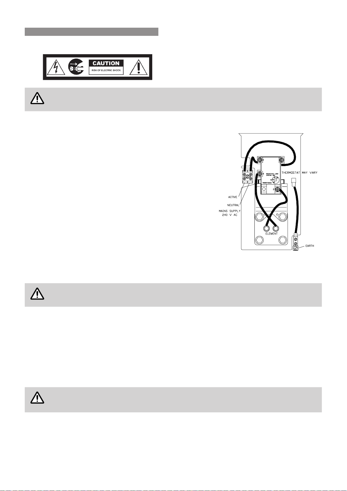
Rinnai 55 CC B OIM
7. Electric Supply
WARNING
The power supply to the heating elements must not be activated until the system is lled with water.
Wiring of Electric Element
The power supply to the element of the solar storage cylinder can
be off-peak (overnight), extended off-peak (overnight and day),
continuous or other tariffs available from the local electricity supply
authority� Rinnai strongly recommends the use of an off-peak tariff to
ensure that solar heating takes priority over electrical heating� If this
tariff isn’t available, then a timer can be used to limit electrical heating
to non solar hours�
A exible 20 mm conduit is required for the electrical cable to the
storage cylinder� The conduit is to be connected to the unit with a 20
mm terminator� Connect the power supply wires directly to the terminal
block and earth tab connections ensuring there are no excess wire
loops inside the front cover�
Heating Element Thermostat Temperature Settings
Australian Standards require a minimum thermostat set point of
60°C to inhibit the growth of Legionella Pneumophilia bacteria� In the
interests of durability, the thermostat set point for storage cylinders
should not exceed 70°C� Hence, the thermostat set point should be at
least 60°C and no greater than 70°C�
FILLING THE SYSTEM
CAUTION
Ensure building occupants are warned to stay clear of the solar system components, building perimeter
and roof since hot water or steam may be discharged from pipes or components�
1� Ensure the electric power supply to the water heater is switched ‘OFF’�
2� Turn ‘ON’ the hot water tap at the sink� Open the stop cock in the cold water mains supply line�
3� The entire system will now be lled with cold water. Most air will be dispelled through the tap. Some air will
need to be bled from the air bleed valve on the collectors�
4� Turn ‘OFF’ the hot tap at the sink when water ows freely without air bubbles or air bursts. Check all connections
for leakage and tighten if necessary. This applies especially to ttings in positions not easily accessed such
as near the solar collectors� Operate the easing gear of both the PTR and ECV valves at the storage cylinder
to ensure these valves are functional�
CAUTION
If leaks are detected the system must be drained and leaks repaired before the system is relled. If
this is necessary, cover the solar collectors with packaging cardboard or a tarp to prevent them from
heating which could result in steam or hot water being discharged from ttings..
INSTALLATION - ELECTRIC BOOSTED SYSTEMS

Rinnai 56 CC B OIM
PRE SOLAR HEATING CHECKS
Before commencing solar heating of the water in the system ensure the following actions have been completed:
Solar Collectors and Cylinder
1� Are the solar collectors installed with the correct slope and orientation to the sun?
2� Is the installation nished neatly with the roof made good, all tiles and ashings in place?
3� Are the bolts tight on the roof framework?
4� Are all solar collector and cylinder straps tted and correctly anchored to the roof structure?
5� If leak testing completed and successful, have any covers been removed from the solar collectors?
Electric Heating Element
1� 1� Has the thermostat set point been set to at least 60°C and no greater than 70°C?
Temperature Limiting Devices
1� Commission any temperature limiting devices in accordance with the instructions supplied by the manufacturer�
2� Conrm the hot water delivery temperature at a tempered water outlet. Tempered water outlets should be
those supplying areas primarily used for the purposes of personal hygiene such as bathrooms� The hot
water delivery temperature should not exceed 50°C or 45°C as detailed in the section ‘Hot Water Delivery
Temperature’ on page 19�
SOLAR HEATING
1� Remove any cardboard or tarp covers that may have been placed over the solar collectors to prevent them
from heating water during installation and commissioning� Solar heating of the water in the cylinder will now
commence when sufcient solar radiation is available.
2� Activate electrical power to both the gas booster�
FINISHING THE INSTALLATION
1� After testing is completed explain to the householder the functions and operation of solar water heater
components and the importance of carrying out Maintenance as per separate warranty document�
2� Complete the installation record at the back of the manual�
3� Leave this manual and the warranty booklet with the householder�
DRAINING INSTRUCTIONS
1� The power supply to the gas booster must be switched off�
2� Close the cold water mains supply stop cock�
3� Open a hot tap to relieve pressure�
4� Disconnect the cold water connection to the Thermo-arrest (T/A) valve�
5� Remove the brass plug on the bottom right hand side of the collector bank�
6� Disconnect the ‘water inlet’ and ‘water outlet’ connections at the gas booster�
7� The system will now drain all water�
INSTALLATION - ELECTRIC BOOSTED SYSTEMS

Installer Details
Installers Name: _______________________________________________________________________
Company Name: _______________________________________________________________________
Company Address: ________________________________________________________________________
_______________________________________________________________________
________________________________________________________________________
Company Contact Details
Telephone: ________________________________________________________________________
Mobile Phone: ________________________________________________________________________
Certicate of Compliance / Certication Number: _____________________________________________
Authorised Persons - Licence Number: ___________________________________________________
Installers Signature: _______________________________________________________________________
Installation Date: _______________________________________________________________________
System Details
Storage Cylinder Model Number : __________________________________________________________
Serial Number: __________________________________________________________
Solar Collector(s) Model Number : __________________________________________________________
Serial Number: __________________________________________________________
Gas Booster Model Number : __________________________________________________________
Serial Number: __________________________________________________________
Installation Address: ________________________________________________________________________
_______________________________________________________________________
________________________________________________________________________
Rinnai 57 CC B OIM
INSTALLATION RECORD

_________________________________________________________________________________________
_________________________________________________________________________________________
_________________________________________________________________________________________
_________________________________________________________________________________________
_________________________________________________________________________________________
_________________________________________________________________________________________
_________________________________________________________________________________________
_________________________________________________________________________________________
_________________________________________________________________________________________
_________________________________________________________________________________________
_________________________________________________________________________________________
_________________________________________________________________________________________
_________________________________________________________________________________________
_________________________________________________________________________________________
_________________________________________________________________________________________
_________________________________________________________________________________________
_________________________________________________________________________________________
_________________________________________________________________________________________
_________________________________________________________________________________________
_________________________________________________________________________________________
_________________________________________________________________________________________
_________________________________________________________________________________________
_________________________________________________________________________________________
_________________________________________________________________________________________
_________________________________________________________________________________________
_________________________________________________________________________________________
_________________________________________________________________________________________
_________________________________________________________________________________________
_________________________________________________________________________________________
_________________________________________________________________________________________
Rinnai 58 CC B OIM
NOTES

_________________________________________________________________________________________
_________________________________________________________________________________________
_________________________________________________________________________________________
_________________________________________________________________________________________
_________________________________________________________________________________________
_________________________________________________________________________________________
_________________________________________________________________________________________
_________________________________________________________________________________________
_________________________________________________________________________________________
_________________________________________________________________________________________
_________________________________________________________________________________________
_________________________________________________________________________________________
_________________________________________________________________________________________
________________________________________________________________________________________
_________________________________________________________________________________________
_________________________________________________________________________________________
_________________________________________________________________________________________
_________________________________________________________________________________________
_________________________________________________________________________________________
_________________________________________________________________________________________
_________________________________________________________________________________________
_________________________________________________________________________________________
_________________________________________________________________________________________
_________________________________________________________________________________________
_________________________________________________________________________________________
_________________________________________________________________________________________
_________________________________________________________________________________________
_________________________________________________________________________________________
_________________________________________________________________________________________
_________________________________________________________________________________________
Rinnai 59 CC B OIM
NOTES

15401115 60 CC B OIM - Issue 3 - September 2017�
Head Office
100 Atlantic Drive,
Keyborough, Victoria 3173
Tel: (03) 9271 6625
Fax: (03) 9271 6622
P.O. Box 460
Braeside, Victoria 3195
National Help Line
Tel: 1300 555 545* Fax: 1300 555 655*
*Cost of a local call higher from mobile or public phones.
Hot Water Service Line
Tel: 1800 000 340
Australia Pty. Ltd.
ABN 74 005 138 769
Internet: www.rinnai.com.au E-mail: [email protected]
Rinnai has a Service and Spare Parts network with personnel who are fully trained
and equipped to give the best service on your Rinnai appliance. If your appliance
requires service, please call our National Help Line. Rinnai recommends that this
appliance be serviced every 3 years.
