
Loading ...
Loading ...
Loading ...
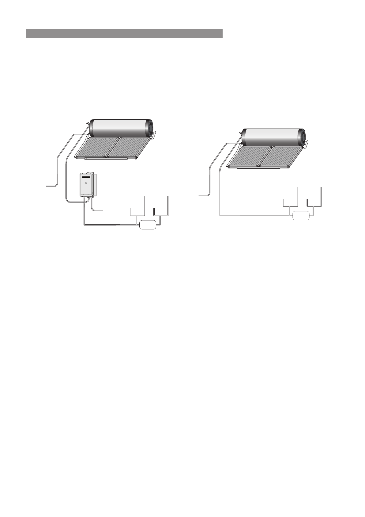
HOT WATER DELIVERY TEMPERATURE
Local regulations and/or the requirements of AS/NZS 3500�4 must be considered regarding the temperature
limitations of hot water supplied to areas used primarily for personal hygiene� The temperature of water to these
areas is limited to 45°C for early childhood centres, primary and secondary schools and nursing homes or similar
facilities for young, aged, sick or people with disabilities and 50°C for all other buildings� To comply with these
requirements, a temperature limiting device, such as a thermostatic mixing or tempering valve, will be required on
all solar hot water systems as detailed below�
COLD WATER
SUPPLY
HEATED WATER
FROM STORAGE
CYLINDER
GAS SUPPLY
KITCHEN
LAUNDRY
ENSUITE
BATHROOM
TEMPERATURE
LIMITING
DEVICE
HEATED WATER
FROM STORAGE
CYLINDER
COLD WATER
SUPPLY
KITCHEN
LAUNDRY
ENSUITE
BATHROOM
TEMPERATURE
LIMITING
DEVICE
Tempered Gas Hot Water System Tempered Electric Hot Water System
VALVES AND FITTINGS
The following valves and ttings are supplied with your solar hot water system:
•
A combined pressure and temperature (PTR) relief valve, capacity 10 kW� Relief valve pressure settings
vary with models. This valve is tted at the top of the storage cylinder. The PTR valve is a safety device and
it is mandatory that it is tted by the installer in all installations.
•
Thermo-Arrestor (TA) valve. This valve is tted on the inlet pipe to the solar collectors. Its function is to
control the ow of water from the tank to the collectors and stop the ow of water when the tank has reached
the required temperature�
•
For gas boosted systems, elbow connections for the hot, cold and gas supply are tted at the bottom of the
gas booster�
•
Fittings as shown on pages 32 to 47
The following valves & ttings are to be supplied by the installer:
•
A cold water expansion control valve (ECV). An ECV must be tted in Western Australia and South Australia
to the cold water supply to the storage cylinder to comply with local regulations� An ECV is recommended
in all other geographical areas where the water supply has a tendency to cause scaling� This will reduce hot
water discharge from the pressure and temperature relief (PTR) valve which minimises wear on this valve�
•
A stop cock, non return valve and line strainer� Combination valves incorporating two or more of these
functions (such as ‘Trio’ valves) are suitable. These are tted to the cold water supply to the storage cylinder
by the installer�
•
Cold water supply and hot water discharge pipework to and from the storage cylinder�
•
An isolating valve and connection union for the gas supply to the gas booster�
•
An approved pressure limiting valve (supplied with some systems) is required if the maximum rated water
supply pressure on page 12 is exceeded�
Rinnai 19 CC B OIM
INSTALLATION - ALL SYSTEMS
Loading ...
Loading ...
Loading ...