Loading ...
Loading ...
3
THREE-PHASE: Three-phase motors require magnetic starters,
and can run in either direction, depending on how they are
connected to the power supply.
Check for Proper Rotation: Remove the motor end cover to expose
the motor shaft. If hookup is correct, the shaft will rotate clockwise.
If rotation is not clockwise, reverse any two leads to the starter. The
rotation will now be correct.
WARNING - RISK OF ELECTRICAL SHOCK
GROUNDING THE MOTOR: WIRING TO THIS PUMP MUST BE
INSTALLED AND MAINTAINED IN ACCORDANCE WITH THE
NATIONAL ELECTRICAL CODE OR YOUR LOCAL ELECTRIC
CODE. IF MORE INFORMATION IS NEEDED, CALL YOUR
LOCAL LICENSED ELECTRICIAN OR YOUR POWER COMPANY.
It is recommended that a permanent ground connection be made
to the unit using a conductor of appropriate size from a metal
underground water pipe or a grounded lead in the service panel.
Do not ground to a gas supply line. Do not connect to electric
power supply until unit is permanently grounded. Connect the
ground wire to the approved ground and then connect to the ter-
minal provided.
The single shallow well (Figure 4) is typically a drilled well with a
4" or 6" steel or plastic casing running vertically into the ground.
The surface of the water should not exceed 25 feet in depth.
Connect the foot valve to the first length of suction pipe and lower
into well. Add pipe sections as needed, securing them using one
of the sealing methods previously mentioned. The foot valve
should be AT LEAST five feet below the surface of the water to
allow for water draw down.
Seal the top of the 4" or 6" well casing with a well seal to prevent
debris from falling into the well.
A. Suction Port Connection (Figure 5)
1. Attach the foot valve or well point to pipe assembly and lower
pipe and foot valve until it is at least five feet below the water
level. If you are using a well, temporarily clamp the pipe to the
well casing to prevent the pipe from sliding into the well. If well
is in a 4" or 6" casing, use a well seal at the surface. Never use
a suction pipe size smaller than the size of the suction port on
the pump.
2. Connect the necessary elbows, fittings, check valves, and
pipe from the water to the pump suction port on front of
pump. When using PVC, pre-assemble pipe and fittings to the
pump BEFORE applying PVC cement to ensure proper cuts
and inventory. Use PTFE tape on all male threads, wrapping
clockwise (when facing pipe) 1 to 2 layers thick. Tighten all
threaded pipe fittings until snug. DO NOT OVER-TIGHTEN
PIPE AND FITTINGS. Tighten joints hand tight plus 1/2 turn
with pipe wrench.
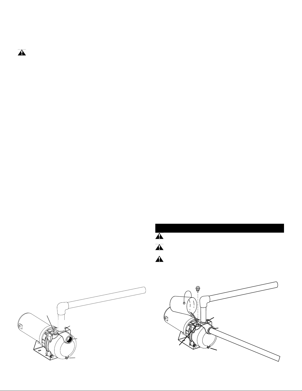
B. Discharge Port Connections (Figure 6)
1. Thread male adapter or pipe nipple into discharge port on top
of pump. (Use PTFE tape on thread)
2. Connect pipe between the sprinkler manifold and the pump
discharge. Discharge pipe size should increase with long pipe
runs. Discharge pipe size may equal discharge port size for
distances up to 100'. Increase discharge pipe size by one size
for distances of 100' to 300'. For 300' to 600', increase pipe
size by two sizes. This will reduce pressure loss caused by
friction.
3. Tighten all threaded pipe connections with pipe wrench until
snug. Do not over tighten.
IMPELLER ROTATION: The impeller must rotate in a counter-
clockwise direction as seen facing the pump from the front of the
casing. In the event of wrong rotation for electric motor models,
refer to the instructions furnished with the motor. The rotation of
three phase motors can be changed by interchanging any two
lead wires.
STARTING THE PUMP: Never operate the pump dry as this may
damage the seal. If an exceptionally long suction line is used,
the water in the pump casing may become overheated or vapour
locked. Should this occur, replace the water in the casing with cold
water and continue priming.
DRAINING: Should the pump be subject to freezing tempera-
tures, it will be necessary to drain the pump completely. To drain,
remove the drain plug located at the bottom of the front face of
the pump casing and the priming plug and make sure that the
drain hole is not restricted. After all the water has been drained,
operating the pump for a few seconds will ensure that the impeller
is devoid of water (make sure that the suction line is also devoid
of water).
PUMP STORAGE: Drain liquid from pump to prevent freezing.
It is recommended that a good rust inhibitor be put in the liquid
end to prevent excessive corrosion. Be sure motor is kept dry
and covered. When restoring the use of the pump, replace all
plugs and make sure all connections are tightly sealed. After a
complete check is made, make the initial prime according to the
OPERATION section.
OPERATION
WARNING: DO NOT run pump against a closed discharge.
This may cause hazardous pressure and risk of explosion.
CAUTION: DO NOT run the pump before priming it. the seal
and impeller could be permanently damaged.
CAUTION: DO NOT run the pump before filling the pump
case with liquid. Doing so may damage the seal.
PRIMING PORT
SUCTION PORT
DRAIN PLUG
DISCHARGE PORT
Figure 6
PRIMING PORT
SUCTION PORT
DRAIN PLUG
DISCHARGE PORT
Figure 7
Loading ...
Loading ...
Loading ...