Loading ...
2
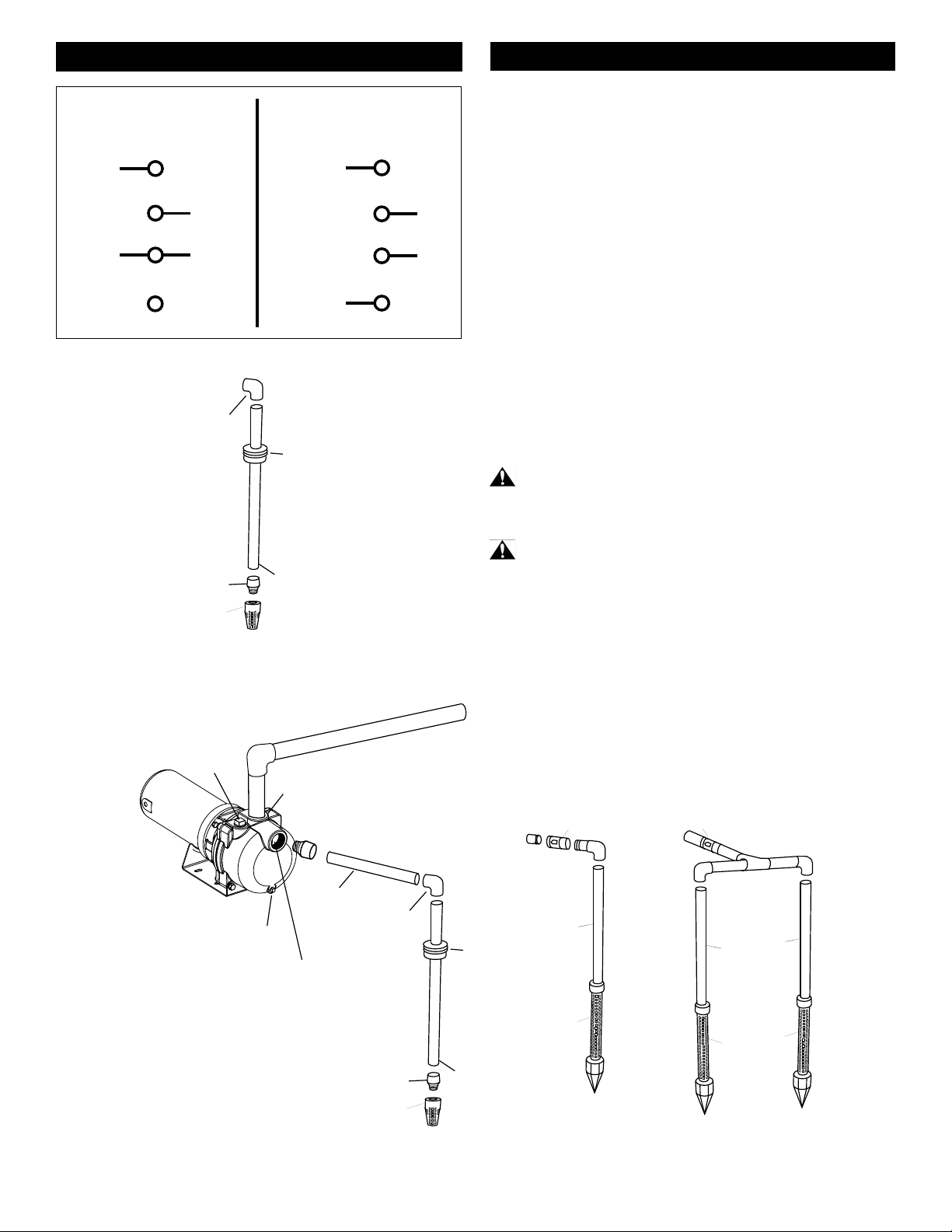
RIDGED PVC PIPE
PVC ADAPTER
FOOT VALVE
ELBOW
WELL
SEAL
Figure 4
WELL POINT
INSTALLATION
MULTIPLE WELL
POINT INSTALLATION
TO SPRINKLER SYSTEM
2” ADAPTER
2" FOOT VALVE
PRIMING PORT
1-1/2" DISCHARGE PORT
DRAIN PLUG
2" SUCTION PORT
2" RIDGED PIPE
ELBOW
WELL SEAL
2” RIDGED PIPE
WELL POINT
2" GALVANIZED PIPE
2" PVC ELBOW
CHECK VALVE
TO PUMP
CHECK VALVE
2" PVC ELBOW
GALVANIZED
PIPE
WELL POINT
Figure 5
INSTALLATION
Pump Location: Install the pump in a clean, dry, and ventilated
location that provides adequate drainage, room for servicing,
and protection from freezing temperatures. Bolt down the pump
evenly on a good foundation, preferably concrete, to prevent the
development of unnecessary stress. Locate the pump as close
as possible to the water supply to reduce friction losses in the
suction pipe and to provide for maximum capacities. A foot valve
must be used.
Suction Pipe: Use only new, clean pipe or hose the same size
as that of the pump suction tapping. If the pump is installed any
appreciable distance away from the water supply, increase the
suction pipe by one size. The suction pipe must always slope
upwards from the water source to the pump to avoid air pockets
in the line. In cases where the pump has to be reprimed often and
it is not necessary that a lot of water be delivered, it is advisable to
use a 90° or 45° elbow on the suction line. This enables the pump
to prime sooner and also prevents kinking of the hose. A check
valve is recommended to ensure easier priming. In cases where
a maximum volume of water is required over a prolonged period,
the suction line should be led almost horizontally to the pump.
Use non-toxic thread compound on all pipe joints, and tighten all
connections thoroughly. Connect a strainer to the bottom end of
the suction pipe and ensure that it is well submerged at all times.
WARNING - RISK OF ELECTRICAL SHOCK
• WIRING: Make sure the voltage and frequency of the power
supply agrees with that stamped on the motor nameplate. If in
doubt, check with the power company.
WARNING - ELECTRICAL PRECAUTIONS
All wiring, electrical connections, and system grounding must
comply with the National Electrical Code (NEC) and with any local
codes and ordinances. Employ a licensed electrician.
SINGLE PHASE: Determine incoming voltage to motor. Where
possible, use 230V. Connect wiring to terminal board located inside
motor end cover. Be sure voltage connections agree with wiring
diagram on motor nameplate.
VOLTAGE WIRING INSTRUCTIONS - 2 HP
115 V
230 V
LINE
LINE
BROWN
WHITE
L1
L2
A
B
BROWN
WHITE
LINE
LINE
L1
L2
A
B
Loading ...
Loading ...
Loading ...