User manual Electric Garage Heater
LOCATING HEATER
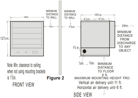
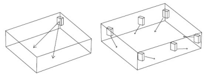
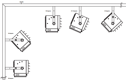
Install heater away from traffic areas, maintaining clearances stated in figure 2 (below). The air flow direction should not be restricted (ie. by columns or machinery). The air flow should wipe exposed walls rather than blowing directly on them. When more than one heater is used in an area, heaters should be installed so that the air discharge of each heater supports the air flow of the others, to provide best warm air circulation as shown in figure 3.
LOCATING HEATER
PRE-INSTALLATION
INSTALLATION
MOUNTING THE BRACKET
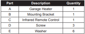
Refer to Figures 4a and 4b.
- Locate a wood stud in the wood ceiling joist. If you cannot locate a wood stud, you have to install a wood piece on the ceiling as this heater must be securely fastened.
- Remove the mounting bracket from the heating unit by loosening bracket screws with a wrench and slipping the handle off over the screw heads.
- Place a washer on screws before inserting through the holes in the mounting bracket and screw them securely into a ceiling joist.
NOTE: If you want to swivel the heater either to the right or left adding a washer to both sides of the bracket is recommended. A longer lag bolt may be required to properly secure the unit. See Figure 4a.
HANGING THE HEATER
- Attach the heating unit to the mounting bracket.
- Lift the heater up and into the mounting bracket.
- Align the bracket screws with the keyhole slots in the mounting bracket.
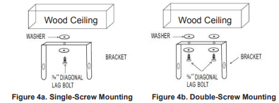
- If the heater is to be tilted it must be positioned in the keyhole slots - see figure 5.
- Tighten the bracket screws with a wrench so the unit is securely suspended at horizontal or vertical level.
ADJUSTING AIR FLOW DIRECTION
- To turn the unit when it has been installed with a single lag bolt (as shown in figure 4a), simply turn the entire heater as needed. The unit cannot be turned horizontally if it has been installed with 2 lag bolts.
- To tilt the unit vertically, loosen the bracket screws (see figure 5).
NOTE: For the heater to be tilted vertically, it must be mounted in bottom keyhole slots of mounting brackets to maintain adequate clearance and prevent possible overheating.
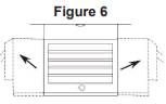
3. Adjust louvers to the desired position (see Figure 6).
NOTE: The louvers are designed so they cannot be completely closed. Do not attempt to bypass this feature; damage to the unit can result.
MULTIPLE VERTICAL ANGLES
CONNECTING THE POWER
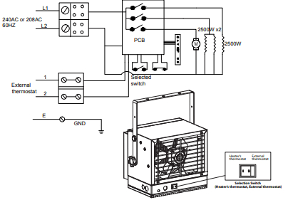
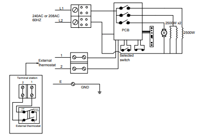
If you will use an external temperature control (external thermostat) to control the heater to be operated or not, please follow below attention points:
1. Make sure that the heater's temperature control knob (thermostat knob) is turned fully clockwise.
2. Connect the wire according to below wiring diagram.
3. The external temperature control (external thermostat) should be in accordance with the requirement of UL or CSA standard.
4. The lead wire of external temperature control (external thermostat) can not be less than 14AWG.
TO PROTECT THE HEATING ELEMENT
When starting the heater, turning the temperature control clockwise slowly to terminal, the unit starts the fan first then starts the heating element.
When shutting off the heater, turning the temperature control counter-clockwise to off, the heating element first will turn off then the fan will run a short cooling cycle and then turn off.
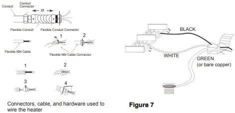
1. Remove the screw from the front of the unit to connect the power to the heater.
2. Attach the cable connectors to the unit (See Figure 7) and slide the 10-gauge wire through the cable connector.
NOTE: All wiring must be carried out by a Certified Electrician and must be in accordance to national and local electrical codes in the United States. For certain applications, conduit may be required, See Figure 7. Check local electrical codes. If you run the wiring in conduit and wish to be able to turn the heater be sure to purchase enough flexible conduit to allow the heater to be turned.
3. Connect the wire to the power block located in the base of the heater - See Figure 7.
4. Turn on the power at the main service.
CONNECTING THE POWER
OPERATING INSTRUCTIONS
Check that the garage heaters outlet grill is not covered or obstructed in anyway, and make sure the power to the unit is switched on.
The garage heater control functions can be accessed in two (2) ways:
• Using the touchpad control panel, located on the front of the garage heater below the air guide plates.
• Using the multifunction remote control unit.
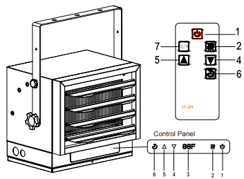
1. Main Power Button:
This button supplies power to all of the garage heaters functions. It must be turned on for the garage heater to work
2. Heater Control Button:
This button adjusts the 3 heating stages: OFF Fa (Fan Only) LOW (5000W displays “L”), High (7500W displays “H”).
3. Temperature/Timer Display:
This LED display shows the set point for the temperature and timer functions. When either of these functions is activated, the display reflects the set point for five seconds and then fades to black. Any change to he set point of the temperature or timer will reactivate the display, which again fades after five seconds.
4. DOWN Control Button:
This button is used to decrease temperature or timer settiing. It adjusts the temperature range between 10°C - 35°C (50°F - 95°F) in 2°F (/1°C) increments.
5. UP Control Button:
This button is increasing temperature or timer setting. It adjusts the temperature range between 10°C - 35°C (50°F - 95°F) in 2°F (/1°C) increments.
6. Timer Button:
This button controls the Timer ON/OFF and 8 settings from 1hour to 8 hours. When the Timer is first turned on, it will come on at the shortest time setting (1hour). Each time the Timer button is pressed, the time increases by 1 hour, up to the longest setting (8 hours). Once the set time expires, all garage heaters functions will be automatically turn off.
7. Fahrenheit/Celsius Button:
REMOTE:
This button displays F (Fahrenheit) or C (Celsius) depending on how the temperature mode is set. When the garage heater is turned on, the Fahrenheit (F) temperature will be displayed.
GARAGE HEATER :
To switch from Fahrenheit to Celsius, or vise-versa, when the garage heater is ON, hold HEATER CONTROL button for 5 seconds. Unless power to the unit has been interrupted, the garage heater will remember the last temperature mode setting will start at that setting,
MAINTENANCE
- Before cleaning, make sure the power has been turned off at the circuit breaker panel and that the heating element of the heater is cool.
- To maintain the external appearance of the heater, the unit occasionally needs to be wiped with a dry duster. During the summer months, or at other times when the appliance is not in use and is completely cold, it should be the wiped over with a damp cloth.
- Do not use abrasive clearing powders or furniture polish. Do not use chemical or abrasive products, metallic scourers and so on, which may deteriorate the surface, to clean the appliance.
- During the summer months, or at other times when the appliance is not in use, disconnect the power supply, and cover the whole appliance with a dustcloth. Moreover, keep the appliance in a dry and cool place.
- All other servicing should be performed by qualified service personnel. Do not try to repair the heater yourself.
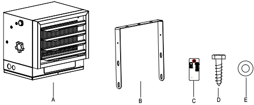
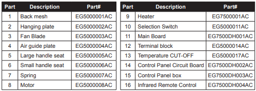
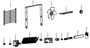
REPLACEMENT PARTS
TROUBLESHOOTING
Unit is not heating
Display shows”EE”
- The thermostat sensor is broken or disconnected.
Please call customer service.
Display shows"EF"
- The overheat protection has activated.
Inspect the garage heater and check that the air inlets and outlets are not blocked as this may cause overheating. Switch off the circuit breaker to the garage heater for 30 minutes and allow it to cool down. Turn the power back on and operate.
Display shows "LOC"
Hold the POWER button for 10 seconds to unlock the heating function.
Display shows "FA" and blows cold air
- The heater is set to FAN ONLY mode
Change the setting and switch to "AUT" heating mode
The heater will not start
- The room temperature has already reached the set thermostat temperature
Adjust the temperature setting to make sure the thermostat setting temperature is higher than current room temperature.
The heater will not start
Rest the breaker at the fuse panel and restart the heater
Garage heater has burned smell
- During production dust and/or oil debris gathered on heating coils.
Make sure the room is well ventilated. Allow the garage heater to run until the smell is dissipated.
- Check and make sure there is no combustible material within 0.9 meter (3 feet) of the garage heater
Remove the combustible material around the garage heater.
- This heater must be mounted at least 8 feet off the floor, for specific clearances, please check the "LOCATING HEATER" section in the instruction manual
Relocate the garage heater so there is enough space between the heater and adjacent wall and floor.