
Issue 03/2019 Art. No. 7001-0292
Operating Manual
BD (E3.1)
|
Incubators
Avantgarde.Line with natural convection
BF (E3.1)
|
Incubators
Avantgarde.Line with forced convection
ED (E3.1)
|
Drying and heating ovens
Avantgarde.Line with natural convection
FD (E3.1)
|
Drying and heating ovens
Avantgarde.Line with forced convection
FED (E3.1)
|
Drying and heating ovens
Avantgarde.Line with forced convection
and enhanced timer functions
with microprocessor temperature controller
Model Model version Art. No. Model Model version Art. No.
BD 56
BD056-230V 9010/ 9110-0323
ED 260
ED260-230V 9010/ 9110-0339
BD056UL-120V 9010/ 9110-0324 ED260UL-240V 9010/ 9110-0340
BD 115
BD115-230V 9010/ 9110-0325 ED 720 ED720-400V 9010/ 9110-0341
BD115UL-120V 9010/ 9110-0326
FD 56
FD056-230V 9010/ 9110-0303
BD 260
BD260-230V 9010/ 9110-0329 FD056UL-120V 9010/ 9110-0304
BD260UL-120V 9010/ 9110-0330
FD 115
FD115-230V 9010/ 9110-0305
BD 720
BD720-230V 9010/ 9110-0331 FD115UL-120V 9010/ 9110-0306
BD720UL-240V 9010/ 9110-0332
FD 260
FD260-230V 9010/ 9110-0309
BF 56
BF056-230V 9010/ 9110-0313 FD260UL-240V 9010/ 9110-0310
BF056UL-120V 9010/ 9110-0314 FD 720 FD720-400V 9010/ 9110-0311
BF 115
BF115-230V 9010/ 9110-0315
FED 56
FED056-230V 9010/ 9110-0295
BF115UL-120V 9010/ 9110-0316 FED056UL-120V 9010/ 9110-0296
BF 260
BF260-230V 9010/ 9110-0319
FED 115
FED115-230V 9010/ 9110-0293
BF260UL-120V 9010/ 9110-0320 FED115UL-120V 9010/ 9110-0294
BF 720
BF720-230V 9010/ 9110-0321
FED 260
FED260-230V 9010/ 9110-0299
BF720UL-240V 9010/ 9110-0322 FED260UL-240V 9010/ 9110-0300
ED 56
ED056-230V 9010/ 9110-0333
FED 720
FED720-400V 9010/ 9110-0301
ED056UL-120V 9010/ 9110-0334 FED720UL-208V 9010/ 9110-0302
ED 115
ED115-230V 9010/ 9110-0335
ED115UL-120V 9010/ 9110-0336
BINDER GmbH
Address: Post office box 102, 78502 Tuttlingen, Germany Phone: +49 7462 2005 0
Fax: +49 7462 2005 100 Internet: http://www.binder-world.com
E-mail: info@binder-world.com Service Hotline: +49 7462 2005 555
Service Fax: +49 7462 2005 93 555 Service E-Mail: service@binder-world.com
Service Hotline USA: +1 866 885 9794 or +1 631 224 4340 x3
Service Hotline Asia Pacific: +852 390 705 04 or +852 390 705 03
Service Hotline Russia and CIS: +7 495 988 15 16

BD / BF / ED / FD / FED (E3.1) 03/2019 page 2/106
Content
1. SAFETY .................................................................................................................. 5
1.1 Legal considerations ........................................................................................................................... 5
1.2 Structure of the safety instructions ...................................................................................................... 5
1.2.1 Signal word panel ...................................................................................................................... 5
1.2.2 Safety alert symbol .................................................................................................................... 6
1.2.3 Pictograms ................................................................................................................................. 6
1.2.4 Word message panel structure ................................................................................................. 7
1.3 Localization / position of safety labels on the chamber ...................................................................... 7
1.4 Type plate............................................................................................................................................ 8
1.5 General safety instructions on installing and operating the chambers ............................................... 9
1.6 Intended use ..................................................................................................................................... 11
2. CHAMBER DESCRIPTION .................................................................................. 12
2.1 Chamber overview ............................................................................................................................ 12
2.2 Triangular instrument panel .............................................................................................................. 13
2.3 Main power switch ED, FD, FED 720 ............................................................................................... 14
3. COMPLETENESS OF DELIVERY, TRANSPORTATION, STORAGE, AND
INSTALLATION .................................................................................................... 14
3.1 Unpacking, and checking equipment and completeness of delivery ................................................ 14
3.2 Guidelines for safe lifting and transportation ..................................................................................... 15
3.3 Storage .............................................................................................................................................. 15
3.4 Location of installation and ambient conditions ................................................................................ 15
4. INSTALLATION .................................................................................................... 17
4.1 Mounting the tilt protection holders (chambers with window) ........................................................... 17
4.2 Electrical connection ......................................................................................................................... 18
4.3 Connection to an exhaust/ventilation system (optional) ................................................................... 19
4.4 Inserting the racks ............................................................................................................................. 20
5. START UP ............................................................................................................ 21
5.1 Behavior when opening the door ...................................................................................................... 21
5.2 Loading.............................................................................................................................................. 21
6. OVERVIEW AND GENERAL SETTINGS ON THE R4 CONTROLLER ............... 22
6.1 Controller overview ........................................................................................................................... 22
6.2 Normal display .................................................................................................................................. 22
6.3 Setting the menu language ............................................................................................................... 23
6.4 Setting date and time ........................................................................................................................ 24
6.5 Selecting the temperature unit .......................................................................................................... 26
6.6 Set-point entry for temperature and fan speed ................................................................................. 27
6.6.1 Set-point entry for temperature in two-door chambers (ED, FD, FED 720) ............................ 28
6.7 Adjusting the air flap position ............................................................................................................ 29
6.8 Changing the passwords for user level and general controller functions ......................................... 30
7. OVERTEMPERATURE PROTECTION ................................................................ 32
7.1 Overtemperature protective device (class 1) .................................................................................... 32
7.2 Safety controller ................................................................................................................................ 33
7.3 Setting the safety controller set-point ................................................................................................ 34
7.4 Alarm message and proceeding in case of an alarm ........................................................................ 35
7.5 Function check .................................................................................................................................. 35
7.6 Disconnectable audible over-temperature alarm (option) ................................................................. 36

BD / BF / ED / FD / FED (E3.1) 03/2019 page 3/106
8. TIMER FUNCTIONS ............................................................................................. 37
8.1 Selecting the timer function ............................................................................................................... 37
8.2 Timer function “Delayed Off” ............................................................................................................. 38
8.2.1 Entry and activation of the timer run-time and fan setting ....................................................... 38
8.2.2 Turning off the timer function or changing the settings ........................................................... 40
8.3 Timer function “Temperature dependent Delayed Off” (BF, FED) .................................................... 42
8.3.1 Entry and activation of the timer run-time, fan setting and set-point entry .............................. 42
8.3.2 Turning off the timer function or changing the settings ........................................................... 44
8.4 Timer function “Delayed On” (BF, FED) ............................................................................................ 45
8.4.1 Entry and activation of the timer run-time and fan setting ....................................................... 45
8.4.2 Changing the settings .............................................................................................................. 47
8.5 Temperature programming example (BF, FED) ............................................................................... 47
9. RAMP FUNCTION ................................................................................................ 48
9.1 General information ........................................................................................................................... 48
9.2 Setting and displaying the ramp function .......................................................................................... 49
9.3 Displaying the effective ramp set-point and changing the target ramp set-point .............................. 50
9.4 Turning off the ramp function ............................................................................................................ 51
10. DATA RECORDING VIA USB INTERFACE ........................................................ 52
10.1 Starting data recording ...................................................................................................................... 52
10.2 Terminating data recording ............................................................................................................... 53
11. NETWORK CONFIGURATION FOR CHAMBERS WITH ETHERNET
INTERFACE ......................................................................................................... 54
12. OPTIONS .............................................................................................................. 57
12.1 APT-COM™ 4 Multi Management Software (option) ........................................................................ 57
12.2 Data logger kits (option) .................................................................................................................... 57
12.3 Object temperature display with additional Pt100 temperature sensor (option) ............................... 57
12.4 Analog output for temperature (option) ............................................................................................. 58
12.5 Water protected disconnectable internal socket (option BD, BF) ..................................................... 58
12.6 HEPA fresh air filter (option for FD, FED) ......................................................................................... 59
12.7 Mostly gas-tight version (option for BF, FD, FED) ............................................................................ 59
12.8 Inert gas connection with mostly gas-tight version (option for BF, FD, FED) ................................... 59
13. MAINTENANCE, CLEANING, AND SERVICE .................................................... 61
13.1 Maintenance intervals, service .......................................................................................................... 61
13.2 Cleaning and decontamination ......................................................................................................... 62
13.2.1 Cleaning .................................................................................................................................. 62
13.2.2 Decontamination ...................................................................................................................... 63
13.3 Sending the chamber back to BINDER GmbH ................................................................................. 64
14. DISPOSAL............................................................................................................ 65
14.1 Disposal of the transport packing ...................................................................................................... 65
14.2 Decommissioning .............................................................................................................................. 65
14.3 Disposal of the chamber in the Federal Republic of Germany ......................................................... 65
14.4 Disposal of the chamber in the member states of the EU except for the Federal Republic of
Germany............................................................................................................................................ 66
14.5 Disposal of the chamber in non-member states of the EU ............................................................... 67
15. TROUBLESHOOTING ......................................................................................... 68
16. TECHNICAL DESCRIPTION ................................................................................ 69
16.1 Factory calibration and adjustment ................................................................................................... 69
16.2 Definition of usable volume ............................................................................................................... 69
16.3 Over current protection ..................................................................................................................... 69
16.4 BD technical data .............................................................................................................................. 70
16.5 BF technical data .............................................................................................................................. 71
16.6 ED technical data .............................................................................................................................. 73

BD / BF / ED / FD / FED (E3.1) 03/2019 page 4/106
16.7
FD technical data .............................................................................................................................. 75
16.8 FED technical data ............................................................................................................................ 76
16.9 Equipment and options (extract) ....................................................................................................... 78
16.10 Accessories and spare parts (extract) .............................................................................................. 79
16.11 Dimensions size 56 ........................................................................................................................... 81
16.12 Dimensions size 115 ......................................................................................................................... 83
16.13 Dimensions size 260 ......................................................................................................................... 85
16.14 Dimensions size 720 ......................................................................................................................... 87
17. CERTIFICATES AND DECLARATIONS OF CONFORMITY ............................... 90
17.1 EU Declaration of Conformity for BD ................................................................................................ 90
17.2 EU Declaration of Conformity for BF ................................................................................................. 92
17.3 EU Declaration of Conformity for ED ................................................................................................ 94
17.4 EU Declaration of Conformity for FD ................................................................................................ 96
17.5 EU Declaration of Conformity for FED .............................................................................................. 98
18. PRODUCT REGISTRATION .............................................................................. 100
19. CONTAMINATION CLEARANCE CERTIFICATE ............................................. 101
19.1 For chambers located outside the USA and Canada ..................................................................... 101
19.2 For chambers located in the USA and Canada .............................................................................. 104
BD / BF / ED / FD / FED (E3.1) 03/2019 page 5/106
Dear customer,
For the correct operation of the chambers, it is important that you read this operating manual completely
and carefully and observe all instructions as indicated. Failure to read, understand and follow the instruc-
tions may result in personal injury. It can also lead to damage to the chamber and/or poor equipment
performance
1. Safety
This operating manual is part of the components of delivery. Always keep it handy for reference. The
device should only be operated by laboratory personnel especially trained for this purpose and familiar
with all precautionary measures required for working in a laboratory. Observe the national regulations on
minimum age of laboratory personnel To avoid injuries and damage observe the safety instructions of the
operating manual.
WARNING
Failure to observe the safety instructions.
Serious injuries and chamber damage.
Observe the safety instructions in this operating manual
Carefully read the complete operating instructions of the chambers.
1.1 Legal considerations
This operating manual is for informational purposes only. It contains information for installing, start-up,
operation and maintenance of the product. Note: the contents and the product described are subject to
change without notice.
Understanding and observing the instructions in this operating manual are prerequisites for hazard-free
use and safety during operation and maintenance. In no event shall BINDER be held liable for any dam-
ages, direct or incidental arising out of or related to the use of this manual.
This operating manual cannot cover all conceivable applications. If you would like additional information,
or if special problems arise that are not sufficiently addressed in this manual, please ask your dealer or
contact us directly by phone at the number located on page one of this manual
Furthermore, we emphasize that the contents of this operating manual are not part of an earlier or exist-
ing agreement, description, or legal relationship, nor do they modify such a relationship. All obligations on
the part of BINDER derive from the respective purchase contract, which also contains the entire and ex-
clusively valid statement of warranty administration. The statements in this manual neither augment nor
restrict the contractual warranty provisions.
1.2 Structure of the safety instructions
In this operating manual, the following safety definitions and symbols indicate dangerous situations fol-
lowing the harmonization of ISO 3864-2 and ANSI Z535.6.
1.2.1 Signal word panel
Depending on the probability of serious consequences, potential dangers are identified with a signal
word, the corresponding safety color, and if appropriate, the safety alert symbol.
DANGER
Indicates an imminently hazardous situation that, if not avoided, will result in death or serious
(irreversible) injury.
BD / BF / ED / FD / FED (E3.1) 03/2019 page 6/106
WARNING
Indicates a potentially hazardous situation which, if not avoided, could result in death or serious
(irreversible) injury
CAUTION
Indicates a potentially hazardous situation which, if not avoided, may result in moderate or minor
(reversible) injury
CAUTION
Indicates a potentially hazardous situation which, if not avoided, may result in damage to the product
and/or its functions or of a property in its proximity.
1.2.2 Safety alert symbol
Use of the safety alert symbol indicates a risk of injury.
Observe all measures that are marked with the safety alert symbol in order to avoid death or
injury.
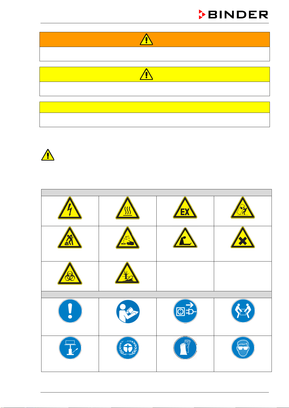
1.2.3 Pictograms
Warning signs
Electrical hazard
Hot surface
Explosive atmosphere
Stability hazard
Lifting hazard
Risk of corrosion and / or
chemical burns
Suffocation hazard
Harmful substances
Biohazard
Pollution Hazard
Mandatory action signs
Mandatory regulation
Read operating
instructions
Disconnect the power
plug
Lift with several persons
Lift with mechanical
assistance
Environment protection
Wear protective gloves
Wear safety goggles
BD / BF / ED / FD / FED (E3.1) 03/2019 page 7/106
Prohibition signs
Do NOT touch
Do NOT spray with
water
Information to be observed in order to ensure optimum function of the product.
1.2.4 Word message panel structure
Type / cause of hazard.
Possible consequences.
∅ Instruction how to avoid the hazard: prohibition.
Instruction how to avoid the hazard: mandatory action.
Observe all other notes and information not necessarily emphasized in the same way, in order to avoid
disruptions that could result in direct or indirect injury or property damage.
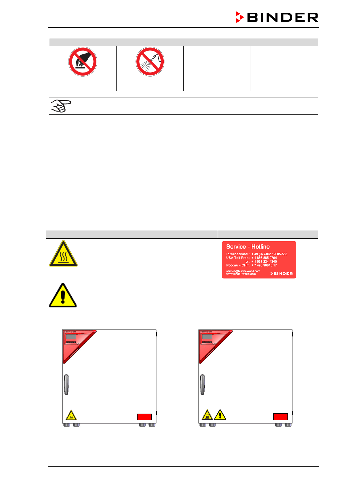
1.3 Localization / position of safety labels on the chamber
The following labels are located on the chamber:
Pictograms (Warning signs)
Service label
Hot surface
• ED, FD, FED: outer chamber door
• BD, BF: on the glass door handle
• On chamber rear next to the exhaust duct
Read operating manual
• UL chamber: outer chamber door
• BD, BF with optional interior socket: below the
interior socket
ED, FD, FED
ED-UL, FD-UL, FED-UL
Figure 1: Position of labels on the chamber front (example: ED, FD, FED size 56)
BD / BF / ED / FD / FED (E3.1) 03/2019 page 8/106
Keep safety labels complete and legible.
Replace safety labels that are no longer legible. Contact BINDER Service for these replacements.
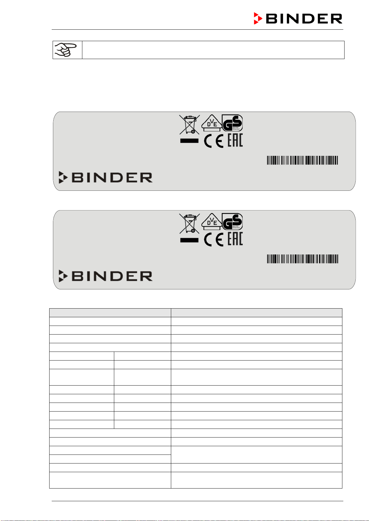
1.4 Type plate
The type plate is located on the left-hand side of the chamber, bottom right-hand.
Figure 2: Type plate (example FED 115-230V regular chamber)
Figure 3: Type plate (example BD 115-230V optional chamber)
Indications of the type plate (example)
Information
BINDER
Manufacturer: BINDER GmbH
BD 115
Model designation
Incubator
Chamber name: Incubator
Drying and heating oven
Chamber name: Drying and heating oven
Serial No.
000000000000
Serial No of the chamber
Built
2019
Year of construction
Nominal temperature
100 °C
212 °F
Nominal temperature
IP protection
20
IP type of protection acc. to EN 60529
Temp. safety device
DIN 12880
Temperature safety device acc. to standard DIN 12880
Class
3.1
Class of temperature safety device
Art. No.
9110-0305
Art. no. of the chamber
Project No.
---
Optional: Special application acc. to project no.
1,30 kW
Nominal power
5,7 A
Nominal current
230 V / 50 Hz
Nominal voltage ± 10%
at the indicated power frequency
230 V / 60 Hz
1 N ~
Current type
With option internal socket:
Nominal power: 0,85 kW
With option internal socket: increased total nominal power
Nominal temp.
300 °C
1,30 kW / 5,7 A
572 °F
230 V / 50 Hz
IP protection
20
230 V / 60 Hz
Safety device
DIN 12880
1 N ~
Class
2.0
Art. No.
9010-0305
Project No.
Built
2019
Drying and heating oven
BINDER GmbH
Im Mittleren Ösch 5
78532 Tuttlingen / Germany
www.binder-world.com
FED 115
E3.1
Serial No. 00000000000000
Made in Germany
Nominal temp.
100 °C
0,35 kW / 1,6 A
With option internal socket:
212 °F
230 V / 50 Hz
Nominal power: 0,85 kW
IP protection
20
230 V / 60 Hz
Safety device
DIN 12880
1 N ~
Class
3.1
Art. No.
9110-0325
Project No.
Built
2019
Incubator
BINDER GmbH
Im Mittleren Ösch 5
78532 Tuttlingen / Germany
www.binder-world.com
BD 115
E3.1
Serial No. 00000000000000
Made in Germany

BD / BF / ED / FD / FED (E3.1) 03/2019 page 9/106
Symbol on the type plate
Information
CE conformity marking
Electrical and electronic equipment manufactured / placed on
the market in the EU after 13 August 2005 and to be disposed of
in a separate collection according to Directive 2012/19/EU on
waste electrical and electronic equipment (WEEE).
The chamber is certified according to Customs Union Technical
Regulation (CU TR) for the Eurasian Economic Union (Russia,
Belarus, Armenia, Kazakhstan Kyrgyzstan).
GS mark of conformity of the “VDE Prüf- und Zertifizierungsinsti-
tut” (Testing and Certification Institute of the Association for
Electrical, Electronic and Information Technologies
(UL chambers only)
The chamber is certified by Underwriters Laboratories Inc.
®
ac-
cording to the following standards:
• UL 61010-1, 3
rd
Edition, 2012-05, rev. 2015-07
• CAN/CSA-C22.2 No. 61010-1, 3
rd
Edition, 2012-
05, rev.
2015-07
1.5 General safety instructions on installing and operating the chambers
With regard to operating the chambers and to the installation location, please observe the DGUV guide-
lines 213-850 on safe working in laboratories (formerly BGI/GUV-I 850-0, BGR/GUV-R 120 or ZH 1/119,
issued by the employers’ liability insurance association) (for Germany).
BINDER GmbH is only responsible for the safety features of the chamber provided skilled electricians or
qualified personnel authorized by BINDER perform all maintenance and repair, and if components relat-
ing to chamber safety are replaced in the event of failure with original spare parts.
To operate the chamber, use only original BINDER accessories or accessories from third-party suppliers
authorized by BINDER. The user is responsible for any risk caused by using unauthorized accessories.
CAUTION
Danger of overheating.
Damage to the chamber.
∅ Do NOT install the chamber in unventilated recesses.
Ensure sufficient ventilation for dispersal of the heat.
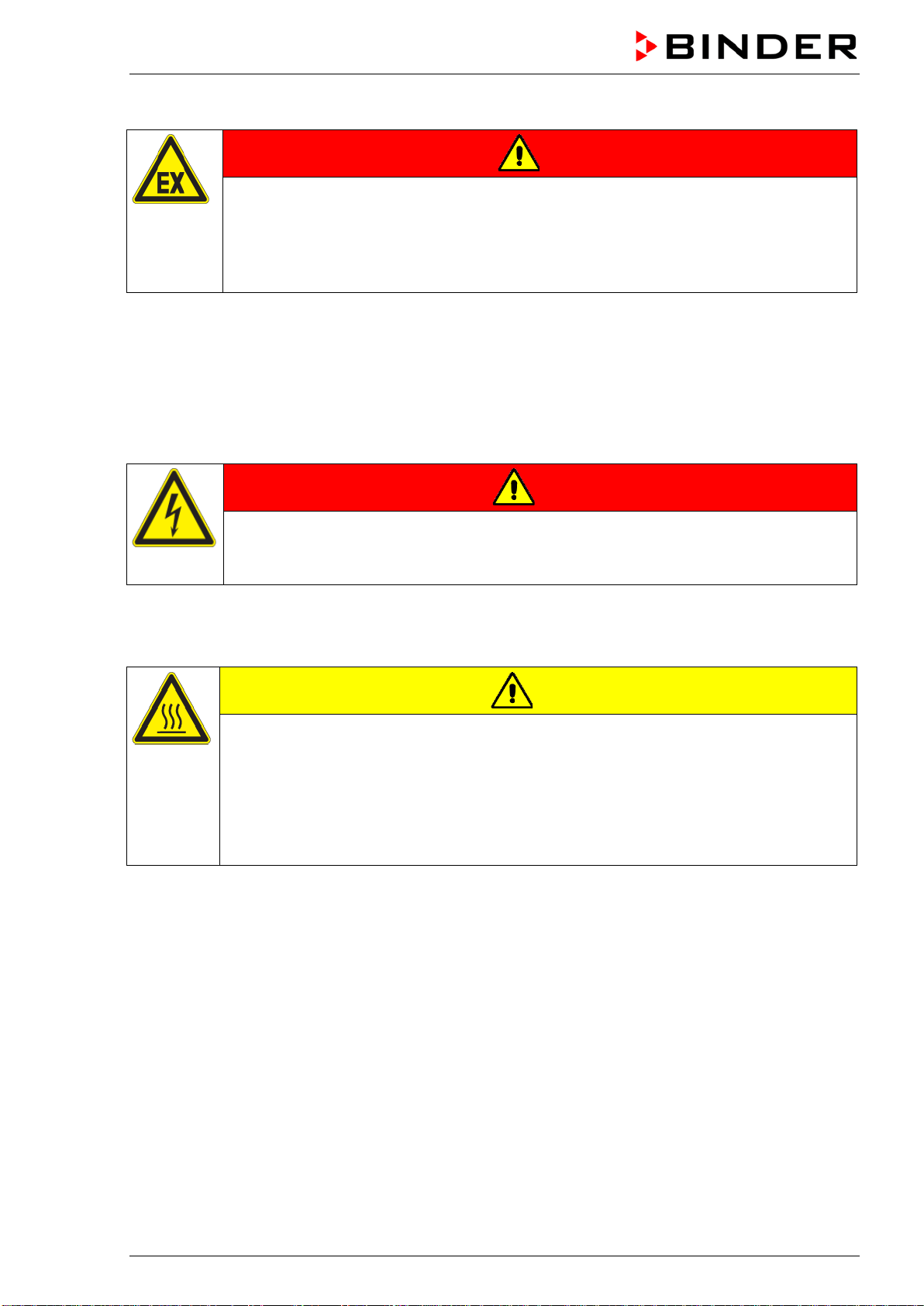
Do not operate the chambers in hazardous locations.
DANGER
Explosion hazard.
Danger of death.
∅ Do NOT operate the chamber in potentially explosive areas.
KEEP explosive dust or air-solvent mixtures AWAY from the chamber.
BD / BF / ED / FD / FED (E3.1) 03/2019 page 10/106
The chambers do not dispose of any measures of explosion protection.
DANGER
Explosion hazard.
Danger of death.
∅ Do NOT introduce any substance into the chamber which is combustible or explosive at
working temperature.
∅ NO explosive dust or air-solvent mixture in the inner chamber.
Any solvent contained in the charging material must not be explosive or inflammable. I.e., irrespective of
the solvent concentration in the steam room, NO explosive mixture with air must form. The temperature
inside the chamber must lie below the flash point or below the sublimation point of the charging material.
Familiarize yourself with the physical and chemical properties of the charging material, as well as the
contained moisture constituent and its behavior with the addition of heat energy.
Familiarize yourself with any potential health risks caused by the charging material, the contained mois-
ture constituent or by reaction products that may arise during the temperature process. Take adequate
measures to exclude such risks prior to putting the chamber into operation.
DANGER
Electrical hazard.
Danger of death.
∅ The chamber must NOT become wet during operation or maintenance.
The chambers were produced in accordance with VDE regulations and were routinely tested in accord-
ance to VDE 0411-1 (IEC 61010-1).
During and shortly after operation, the temperature of the inner surfaces almost equals the set-point.
CAUTION
The
glass doors and glass door handles (BD, BF), inner chamber, exhaust duct, door
window (option), and the door gaskets will become hot during operation.
Danger of burning.
∅ Do NOT touch the glass doors, inner surfaces, exhaust duct, door window, access
ports, door gaskets, or the charging material during operation.
∅ BF, FD, FED: Do not place the power cable over the door gap when the chamber is hot
after operation.

BD / BF / ED / FD / FED (E3.1) 03/2019 page 11/106
1.6 Intended use
The chambers are suitable for exact tempering of harmless materials and for drying and heat treatment of
solid or pulverized charging material, as well as bulk material, using the supply of heat. They can be used
to dry e.g. glassware, and for warm storage of liquids in containers.
Because of their precise temperature accuracy the incubators BD and BF are especially useful for incuba-
tion of cultures at a standard temperature of 37 °C / 98.6 °F.
A solvent content must not be explosive or flammable. A mixture of any component of the charging mate-
rial with air must NOT be explosive. The operating temperature must lie below the flash point or below the
sublimation point of the charging material. Any component of the charging material must NOT be able to
release toxic gases.
Other applications are not approved.
The chambers are not classified as medical devices as defined by the Medical Device Directive
93/42/EEC.
Do NOT use the chamber for drying processes when large quantities of vapor would form and result in
condensation.
Due to the special demands of the Medical Device Directive 93/42/EEC, these ovens are not
qualified for sterilization of medical devices as defined by the directive.
Observing the instructions in this operating manual and conducting regular maintenance work
(chap. 13) is part of the intended use.
WARNING: If customer should use a BINDER chamber running in non-supervised continu-
ous operation, we strongly recommend in case of inclusion of irrecoverable specimen or
samples to split such specimen or samples and store them in at least two chambers, if this is
feasible.
The charging material shall not contain any corrosive ingredients that may damage the ma-
chine components. Such ingredients include in particular acids and halides. Any corrosive
damage caused by such ingredients is excluded from liability by BINDER GmbH.
The chambers do not dispose of any measures of explosion protection.
DANGER
Explosion or implosion hazard.
Danger of poisoning.
Danger of death.
∅ Do NOT introduce any substance combustible or explosive at working temperature into
the chamber, in particular no energy sources such as batteries or lithium-ion batteries.
∅ NO explosive dust or air-solvent mixture in the inner chamber.
∅ Do NOT introduce any substance which could lead to release of toxic gases.
In case of foreseeable use of the device there is no risk for the user through the integration of the cham-
ber into systems or by special environmental or operating conditions in the sense of EN 61010-1:2010.
For this, the intended use of the chamber and all its connections must be observed.
Connect only external devices to the chamber interfaces Ethernet (regular with FED, optional with BD,
BF, ED, FD) and USB which are compliant with the standards EN 61010-1:2010 or EN 60950-1:2006
mod.
BD / BF / ED / FD / FED (E3.1) 03/2019 page 12/106
2. Chamber description
BINDER incubators BD and BF and drying and heating ovens ED, FD and FED are equipped with an
electronic PID-controller with digital display.
The incubators BD and BF indicate the temperature with an accuracy of a tenth of a degree.
The drying and heating ovens ED, FD and FED indicate the temperature with an accuracy of
one degree.
All chambers are heated electrically. Incubators BD and drying and heating ovens ED are ventilated nat-
urally. Incubators BF and drying and heating ovens FD and FED are ventilated by fan-assisted, forced-air
circulation.
The concept of air conduction guarantees high level of spatial and time-based temperature precision,
thanks to the direct and distributed air circulation into the interior. With BF, FD and FED, the fan supports
exact attainment and maintenance of the desired temperature accuracy.
The chambers are regularly equipped with an overtemperature safety device class 1 acc. to
DIN12880:2007 and with an overtemperature safety controller (overtemperature temperature safety de-
vice class 2 or class 3.1 acc. to DIN12880:2007), see chap. 7).
The inner chamber and the inside of the doors are made of stainless steel V2A (German material no.
1.4301, US equivalent AISI 304 and material no. 1.4016, US equivalent AISI 430). Drying and heating
ovens ED, FD and FED: When operating the chambers at temperatures above 150 °C / 302 °F, the im-
pact of the oxygen in the air may cause discoloration of the metallic surfaces (yellowish-brown or blue) by
natural oxidation processes. These colorations are harmless and will in no way impair the function or
quality of the chamber. The housing is RAL 7035 powder-coated. All corners and edges are also com-
pletely coated.
All chamber functions are easy and comfortable to use thanks to their clear arrangement. Major features
are easy cleaning of all chamber parts and avoidance of undesired contamination.
The chambers are regularly (FED) or optionally equipped with an Ethernet interface for computer com-
munication, e.g. via the APT-COM™ 4 Multi Management Software (option, chap. 12.1) and with a USB
interface to read out the measured values in real time.
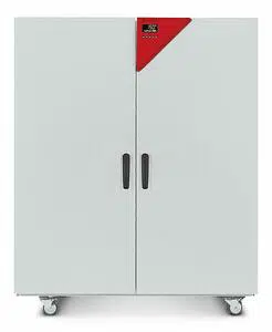
The models size 720 are equipped with
four castors. Both front castors can be locked by brakes.
Temperature ranges see technical data (chap. 16.4 - 16.8).
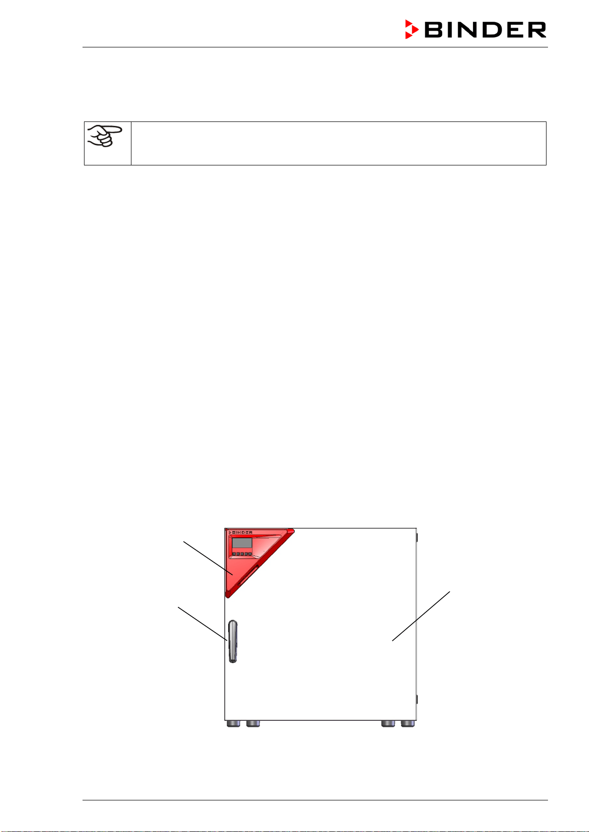
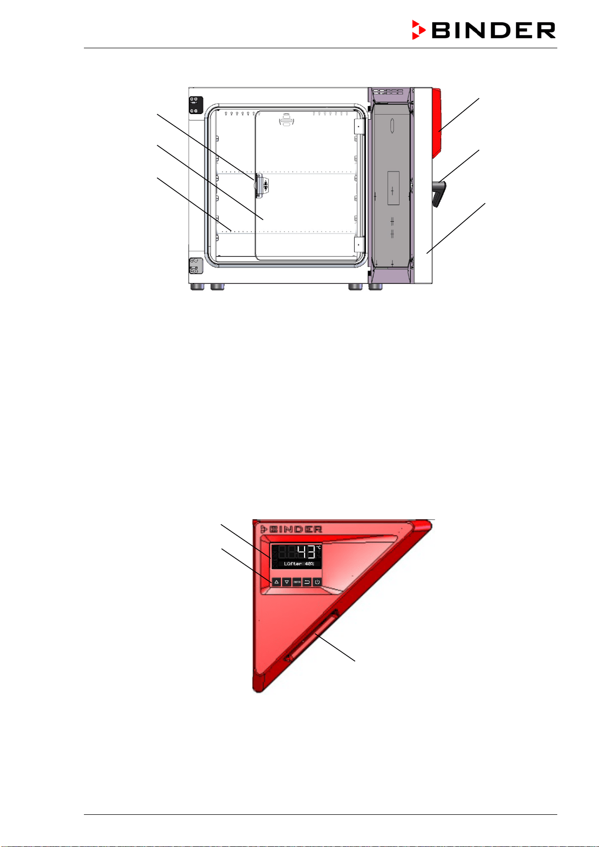
2.1 Chamber overview
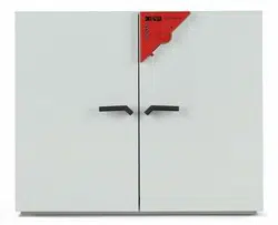
Figure 4: Overview, closed chamber (chamber with single door)
(2)
(3)
(1)
BD / BF / ED / FD / FED (E3.1) 03/2019 page 13/106
Figure 5: Overview, open chamber with glass door (chamber with single door) (BD, BF)
(1) Triangular instrument panel with controller R4 and USB interface
(2) Door handle
(3) Outer door
(4) Glass door handle (BD and BF)
(5) Glass door (BD and BF)
(6) Rack
2.2 Triangular instrument panel
Figure 6: Triangular instrument panel
(7) Controller display
(8) Functional controller buttons
(9) USB interface
(4)
(3)
(6)
(5)
(1)
(2)
(9)
(8)
(7)
BD / BF / ED / FD / FED (E3.1) 03/2019 page 14/106
2.3 Main power switch ED, FD, FED 720
The chambers ED, FD, FED size 720 are equipped with a main power switch located on the chamber
rear.
Off On
Figure 7: Main power switch on the chamber rear
3. Completeness of delivery, transportation, storage, and installa-
tion
3.1 Unpacking, and checking equipment and completeness of delivery
After unpacking, please check the chamber and its optional accessories, if any, based on the delivery
receipt for completeness and for transportation damage. Inform the carrier immediately if transportation
damage has occurred.
The final tests of the manufacturer may have caused traces of the racks on the inner surfaces. This has
no impact on the function and performance of the chamber.
Please remove any transportation protection devices and adhesives in/on the chamber and on the doors
and take out the operating manuals and accessory equipment.
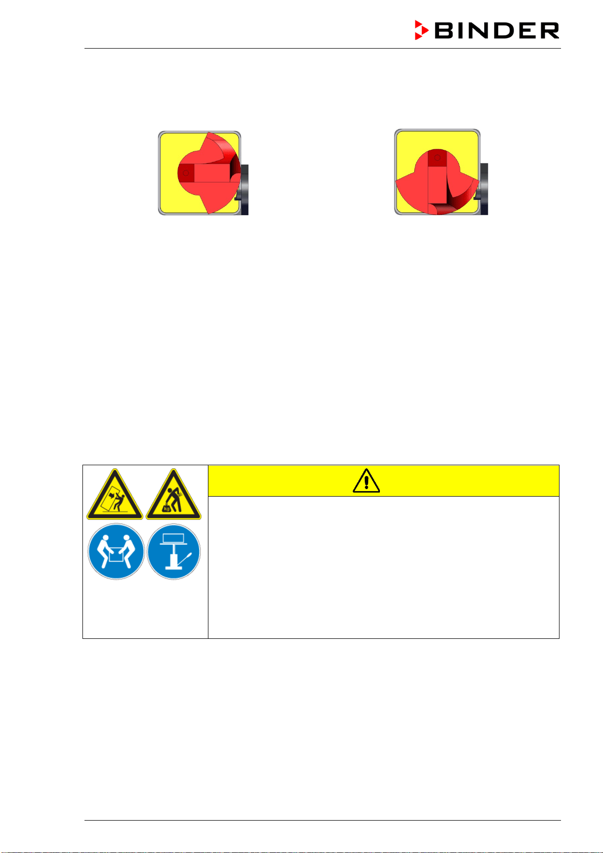
CAUTION
Sliding or tilting of the chamber.
Damage to the chamber.
Risk of injury by lifting heavy loads.
∅ Do NOT lift or transport the chamber using the door handle or the door.
∅ Do NOT lift chambers size 720 by hand
Lift the chamber size 56 and 115 from the pallet at its four lower corners
with the aid of 2 people, chamber size 260 with the aid of 4 people.
Lift chambers size 720 from the pallet using technical devices (fork lifter).
Set the fork lifter only from the rear in the middle of the chamber. Make
sure to place all the lateral supports of the chamber on the forks.
If you need to return the chamber, please use the original packing and observe the guidelines for safe
lifting and transportation (chap. 3.2).
For disposal of the transport packing, see chap. 14.1.
Note on second-hand chambers (Ex-Demo-Units):
Second-hand chambers are chambers that have been used for a short time for tests or exhibitions. They
are thoroughly tested before resale. BINDER ensures that the chamber is technically sound and will work
flawlessly.
Second-hand chambers are marked with a sticker on the chamber door. Please remove the sticker before
commissioning the chamber.
BD / BF / ED / FD / FED (E3.1) 03/2019 page 15/106
3.2 Guidelines for safe lifting and transportation
The front castors of chambers size 720 can be blocked by brakes. Please move the chambers with cas-
tors only when empty and on an even surface, otherwise the castors may be damaged. After operation
please observe the guidelines for temporarily decommissioning the chamber (chap. 14.2).
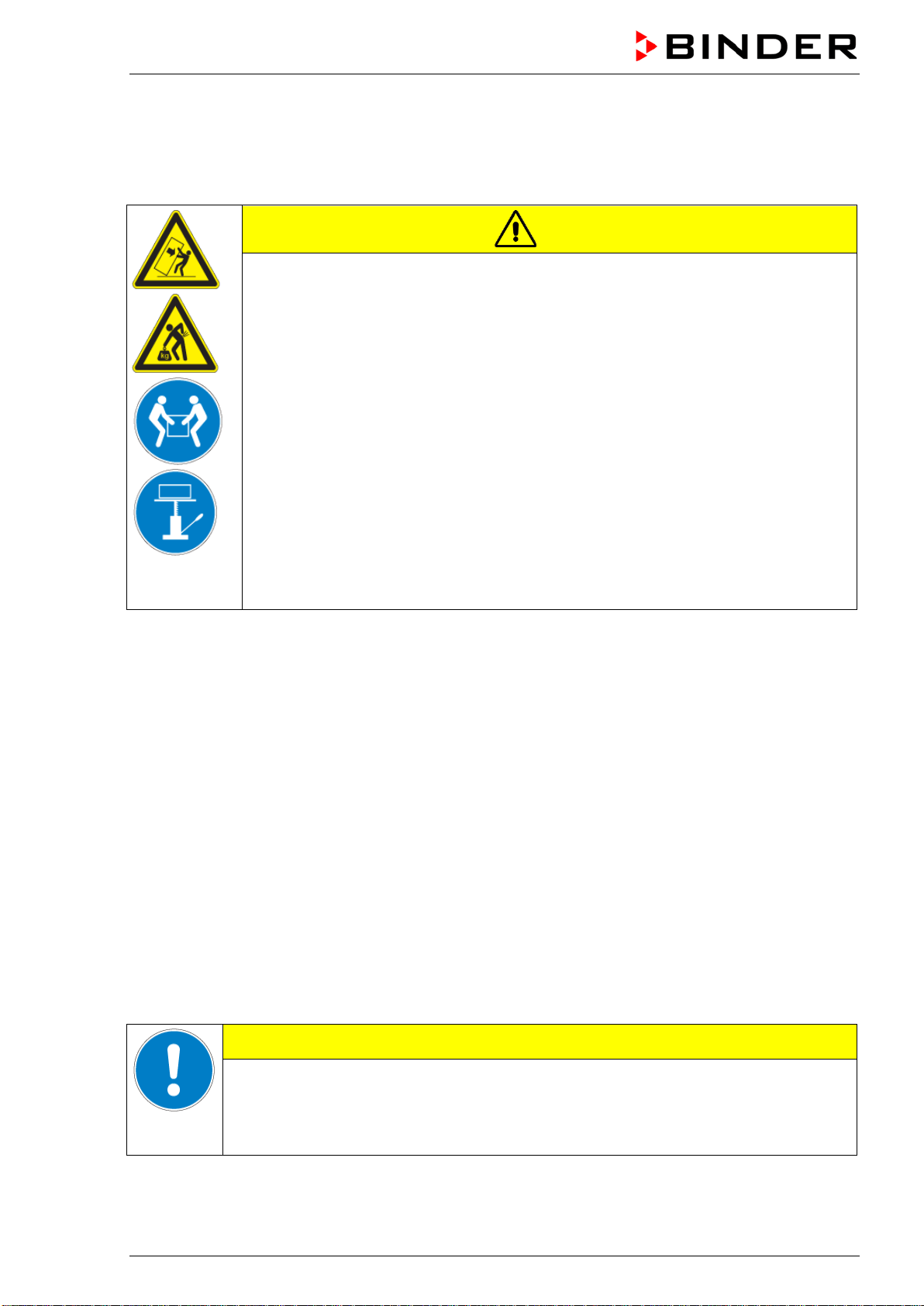
CAUTION
Sliding or tilting of the chamber.
Damage to the chamber.
Risk of injury by lifting heavy loads.
Transport the chamber only in its original packaging.
Secure the chamber with transport straps for transport.
∅ Do NOT lift or transport the chamber using the door handle or the door.
∅ Do NOT lift chambers size 720 by hand
Lift chamber size 56 and 115 at its four lower corners with the aid of 2 people,
chamber size 260 with the aid of 4 people, and place it on a transport pallet with
wheels. Push the pallet to the desired site and then lift the chamber from the pallet at
its four lower corners.
Place chamber size 720 using technical devices (fork lifter) on the transport pallet.
Set the fork lifter only from the rear in the middle of the chamber. Make sure to place
all the lateral supports of the chamber on the forks.
Transport chamber size 720 ONLY with the original transport pallet. Set the fork lifter
only to the pallet. Without the pallet the chamber is in imminent danger of overturn-
ing!
• Permissible ambient temperature range during transport: -10 °C to +60 °C / 14 °F to 140 °F.
You can order transport packing and pallets for transportation purposes from BINDER Service.
3.3 Storage
Intermediate storage of the chamber is possible in a closed and dry room. Observe the guidelines for
temporary decommissioning (chap. 14.2).
• Permissible ambient temperature range during storage: -10 °C to +60 °C / 14 °F to 140 °F.
• Permissible ambient humidity: max. 70 % r.H., non-condensing
When after storage in a cold location you transfer the chamber to its warmer installation site, condensa-
tion may form. Before start-up, wait at least one hour until the chamber has attained ambient temperature
and is completely dry.
3.4 Location of installation and ambient conditions
Set up the chamber on an even and non-flammable surface, free from vibration and in a well-ventilated,
dry location and align it using a spirit level. The site of installation must be capable of supporting the
chamber’s weight (see technical data, chap. 16.4 to 16.7). The chambers are designed for setting up
inside a building (indoor use).
CAUTION
Danger of overheating.
Damage to the chamber.
∅ Do NOT set up chambers in non-ventilated recesses.
Ensure sufficient ventilation for dispersal of the heat.
BD / BF / ED / FD / FED (E3.1) 03/2019 page 16/106
• Permissible ambient temperature range during operation: +18 °C up to +40 °C / 64.4 °F to 104 °F. At
elevated ambient temperature values, fluctuations in temperature can occur.
The ambient temperature should not be substantially higher than the indicated ambient
temperature of +25 °C / 77 °F to which the specified technical data relate. For other ambi-
ent conditions, deviations from the indicated data are possible.
• Permissible ambient humidity: 70 % r.H. max., non-condensing.
• Installation height: max. 2000 m / 6562 ft. above sea level.
When placing several chambers of the same size side by side, maintain a minimum distance of 250 mm /
9.84 in between each chamber. Wall distances: rear 160 mm / 6.30 in, sides 100 mm / 3.94 in. Spacing
above the chamber of at least 100 mm / 3.94 in must also be accounted for.
Two devices up to size 115 can be stacked on top of each other. For this purpose place rubber pads un-
der all four feet of the upper chamber to prevent the device from slipping.
CAUTION
Sliding or tilting of the upper chamber.
Damage to the chambers.
When stacking, place rubber pads under all four feet of the upper chamber.
Stack only chambers of the same size.
Chambers sizes 260 and 720 must NOT be stacked.
CAUTION
Danger by stacking.
Damage to the chambers.
∅ Do NOT place chambers sizes 260 or 720 on top of each other.
To completely separate the chamber from the power supply, you must disconnect the power plug. Install
the chamber in a way that the power plug is easily accessible and can be easily pulled in case of danger.
Do not conduct the power cable above the exhaust duct.
For the user there is no risk of temporary overvoltages in the sense of EN 61010-1:2010.
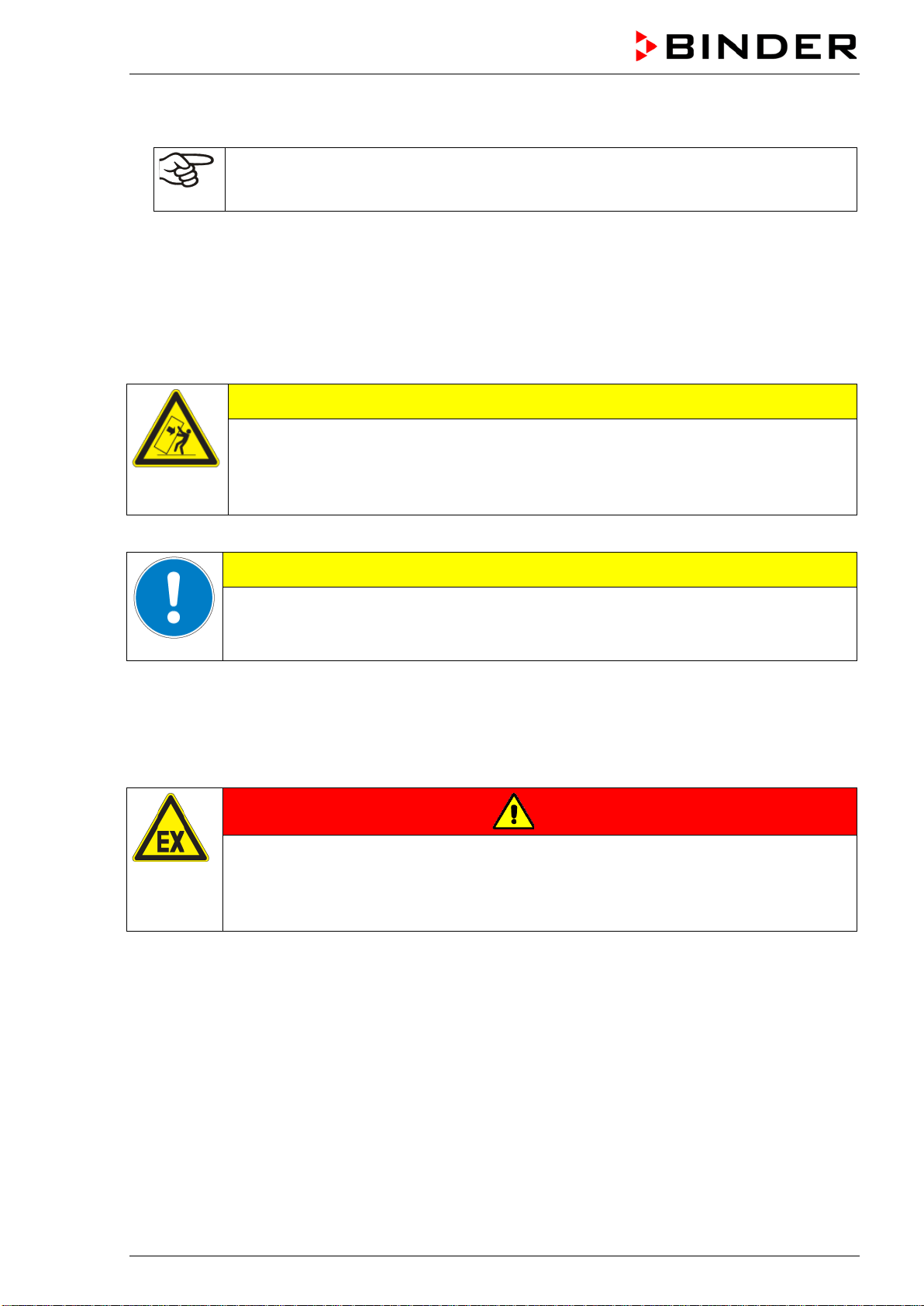
Do not install or operate the chamber in potentially explosive areas.
DANGER
Explosion hazard.
Danger of death.
∅ Do NOT operate the chamber in potentially explosive areas.
KEEP explosive dust or air-solvent mixtures AWAY from the vicinity of the chamber.
BD / BF / ED / FD / FED (E3.1) 03/2019 page 17/106
4. Installation
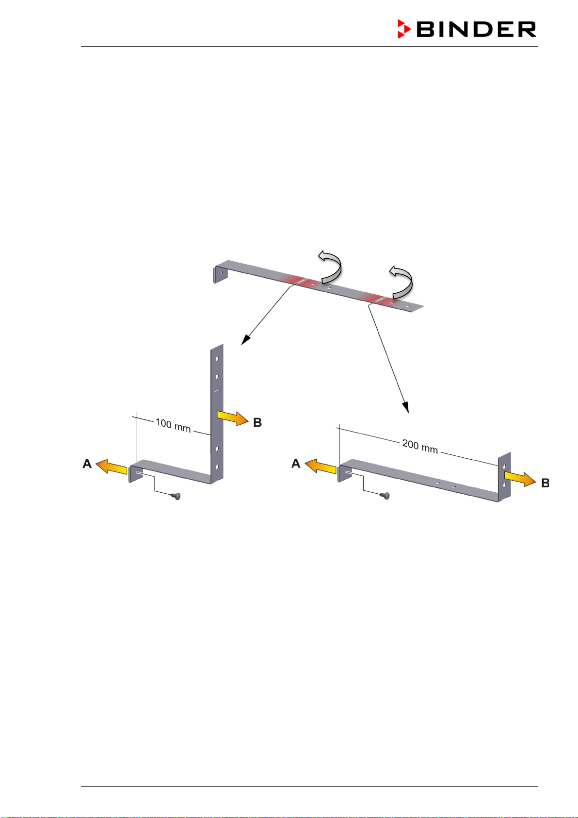
4.1 Mounting the tilt protection holders (chambers with window)
For chambers equipped with the option „door with window“ it is recommended to install the supplied tilt
protection.
Scope of delivery of tilt protection kit (Art.no. 8009-0870):
• 2 screws
• 2 tilt protection holders
Preparing the tilt protection holders
• Depending on the desired wall distance, you can bend the tilt protection holders accordingly.
Figure 8: Variable length of the tilt protection holder depending on the bend
Installation on the chamber
• Plug the two tilt protection holders each with the tab on the provided spot on the edge of the rear pan-
el. The screw holes in the rear wall and in the tilt protection holders must align.
• Fix the tilt protection holders each with one of the supplied screws on the chamber rear wall.
Wall mounting
• Then fix both tilt protection holders on the wall, each with 2 screws Ø 6mm suitable for the wall (B)

BD / BF / ED / FD / FED (E3.1) 03/2019 page 18/106
4.2 Electrical connection
The chambers are supplied ready for connection and come with an IEC connector plug.
Model
Power plug of the
power cable
Nominal voltage +/- 10% at the
indicated power frequency
Current
type
Chamber
fuse
BD056-230V
BF056-230V
Shockproof plug
230 V at 50 Hz
230 V at 60 Hz
1N~ 6,3 A
ED056-230V
FD056-230V
FED056-230V
Shockproof plug
230 V at 50 Hz
230 V at 60 Hz
1N~ 6,3 A
BD115-230V
BF115-230V
Shockproof plug
230 V at 50 Hz
230 V at 60 Hz
1N~ 6,3 A
ED115-230V
FD115-230V
FED115-230V
Shockproof plug
230 V at 50 Hz
230 V at 60 Hz
1N~ 6,3 A
BD260-230V
BF260-230V
Shockproof plug
230 V at 50 Hz
230 V at 60 Hz
1N~ 8,0 A
ED260-230V
FD260-230V
FED260-230V
Shockproof plug
230 V at 50 Hz
230 V at 60 Hz
1N~ 12,5 A
BD720-230V
BF720-230V
Shockproof plug
230 V at 50 Hz
230 V at 60 Hz
1N~ 12,5 A
ED720-400V
FD720-400V
FED720-400V
Shockproof plug
400 V at 50 Hz
400 V at 60 Hz
3N~ ---
BD056UL-120V
BF056UL-120V
NEMA 5-15P
120 V at 50 Hz
120 V at 60 Hz
1N~ 12,5 A
ED056UL-120V
FD056UL-120V
FED056UL-120V
NEMA 5-15P
120 V at 50 Hz
120 V at 60 Hz
1N~ 12,5 A
BD115UL-120V
BF115UL-120V
NEMA 5-15P
120 V at 50 Hz
120 V at 60 Hz
1N~ 12,5 A
ED115UL-120V
FD115UL-120V
FD115UL-120V
NEMA 5-15P
120 V at 50 Hz
120 V at 60 Hz
1N~ 12,5 A
BD260UL-120V
BF260UL-120V
NEMA 5-15P
120 V at 50 Hz
120 V at 60 Hz
1N~ 12,5 A
ED260UL-240V
FD260UL-240V
FED260UL-240V
NEMA 6-20P
240 V at 50 Hz
240 V at 60 Hz
2~ ---
BD720UL-240V
BF720UL-240V
NEMA 6-20P
240 V at 50 Hz
240 V at 60 Hz
2~ ---
FED720UL-208V
NEMA L21-20P
208 V at 50 Hz
208 V at 60 Hz
3N~ ---
BD / BF / ED / FD / FED (E3.1) 03/2019 page 19/106
• The domestic socket must also provide a protective conductor. Make sure that the connection of the
protective conductor of the domestic installations to the chamber’s protective conductor meets the
latest technology. The protective conductors of the socket and plug must be compatible!
• Prior to connection and start-up, check the power supply voltage. Compare the values to the specified
data located on the chamber’s type plate (left-hand side of the chamber, chap. 1.4).
• When connecting, please observe the regulations specified by the local electricity supply company
and as well as the VDE directives (for Germany). We recommend the use of a residual current circuit
breaker.
• Only use original connection cables from BINDER.
• BF, FD, FED: Do not place the power cable over the door gap when the chamber is hot after operati-
on.
• Pollution degree (acc. to IEC 61010-1): 2
• Over-voltage category (acc. to IEC 61010-1): II
CAUTION
Danger of incorrect power supply voltage.
Damage to the equipment.
Check the power supply voltage before connection and start-up.
Compare the power supply voltage with the data indicated on the type plate.
See also electrical data (chap. 16.4 to 16.7).
To completely separate the chamber from the power supply, you must disconnect the power
plug. Install the chamber in a way that the power plug is easily accessible and can be easily
pulled in case of danger.
4.3 Connection to an exhaust/ventilation system (optional)
Active suction from the chamber must only be effected together with external air. Therefore, the cham-
ber’s exhaust air duct shall not be immediately connected to an active exhaust system.
When connecting to an active exhaust system, proceed as follows:
• Perforate the connecting piece between the exhaust air duct and the exhaust system.
Or
• Use an exhaust air funnel placed in a distance of 3-5 cm / 1 to 2 in from the exhaust air duct. The
funnel’s opening must be at least twice as large as the diameter of the exhaust air duct.
If improperly connected to an active exhaust/ventilation system, the spatial temperature
exactitude (uniformity), the heating-up and recovering times as well as the maximum tem-
perature of the chamber may be negatively affected.
CAUTION
The exhaust duct will become hot during operation.
Danger of burning.
∅ Do NOT touch the exhaust duct during operation.

BD / BF / ED / FD / FED (E3.1) 03/2019 page 20/106
4.4 Inserting the racks
Observe the correct orientation of the racks:
Standard rack: The lateral brackets must be above the rack surface when inserting the rack.
Optional heavy load rack: The lateral brackets must be below the rack surface when inserting the rack.
Standard rack Optional heavy load rack
Figure 9: Correct orientation when inserting the racks
WARNING
Overload of the racks.
Risk of injury.
∅ Do not exceed the maximum permissible load per rack.
∅ Do not exceed the maximum permissible total load.
Use only racks intended for this chamber model.
Observe the correct orientation of the racks when inserting them.
Gently place the load on the racks.
BD / BF / ED / FD / FED (E3.1) 03/2019 page 21/106
5. Start up
Insert the plug into a suitable socket (chap. 4.2).
BF, FD, FED size 720: Turn the chamber at the main power switch (chap. 2.3).
If there is no other indication on the controller than the standby symbol, press the standby button
until the display lights up.
The controller now shows normal display (chap. 6.2). If a timer function was active prior to turning off the
chamber, it is shown in the controller display.
Warming chambers may release odors in the first few days after commissioning. This is not a
quality defect. To reduce odors quickly we recommend heating up the chamber to its nominal
temperature for one day and in a well-ventilated location.
5.1 Behavior when opening the door
BD, ED: Depending on the temperature, heating performance may be adapted when opening the door.
BF, FD, FED: When opening the door, heating and fan turn off as long as the door remains open.
5.2 Loading
When loading the chamber, observe the maximum permissible load per rack and the maximum permissi-
ble total load (see tecnical data, chap. 16.4 to 16.8).
Observe the correct orientation of the racks (chap. 4.4).
WARNING
Overload of the racks.
Risk of injury.
∅ Do not exceed the maximum permissible load per rack.
∅ Do not exceed the maximum permissible total load.
Use only racks intended for this chamber model.
Observe the correct orientation of the racks when inserting them.
Gently place the load on the racks.
BD / BF / ED / FD / FED (E3.1) 03/2019 page 22/106
6. Overview and general settings on the R4 controller
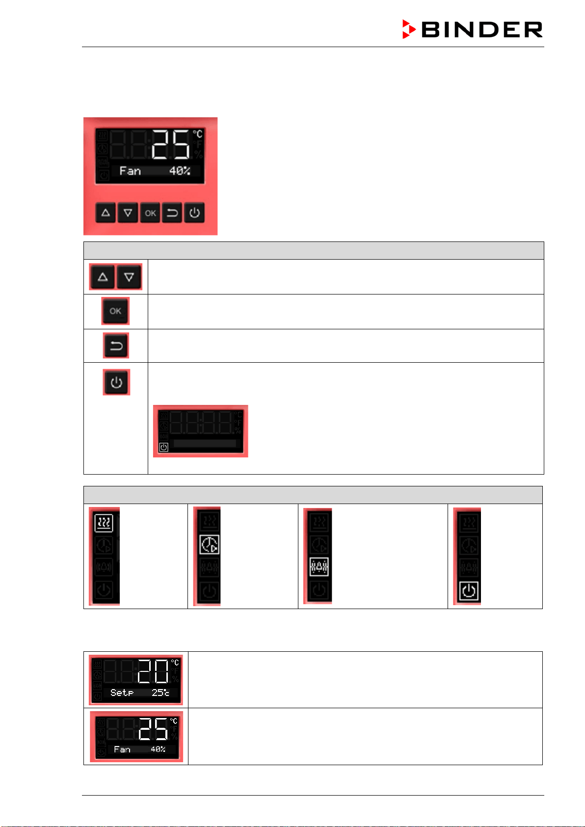
6.1 Controller overview
Buttons on the controller
The arrow buttons serve to navigate and to enter the values
The OK button serves to select the parameters and to confirm the entered values
The Back button serves to reach the preceding level
If the Standby button is pressed down for approx. 3 seconds, the display changes to
standby mode. To activate the display, press down the standby button again for approx.
3 seconds
Display in standby mode with standby symbol
Status symbols on the controller display
Heating
active
Timer
operation
Overtemperature
alarm of the safety
controller
Standby
mode
6.2 Normal display
Normal display with chambers without fan (BD, ED)
or with fixed fan speed (FD)
Normal display with chambers with adjustable fan speed (BF, FED)
BD / BF / ED / FD / FED (E3.1) 03/2019 page 23/106
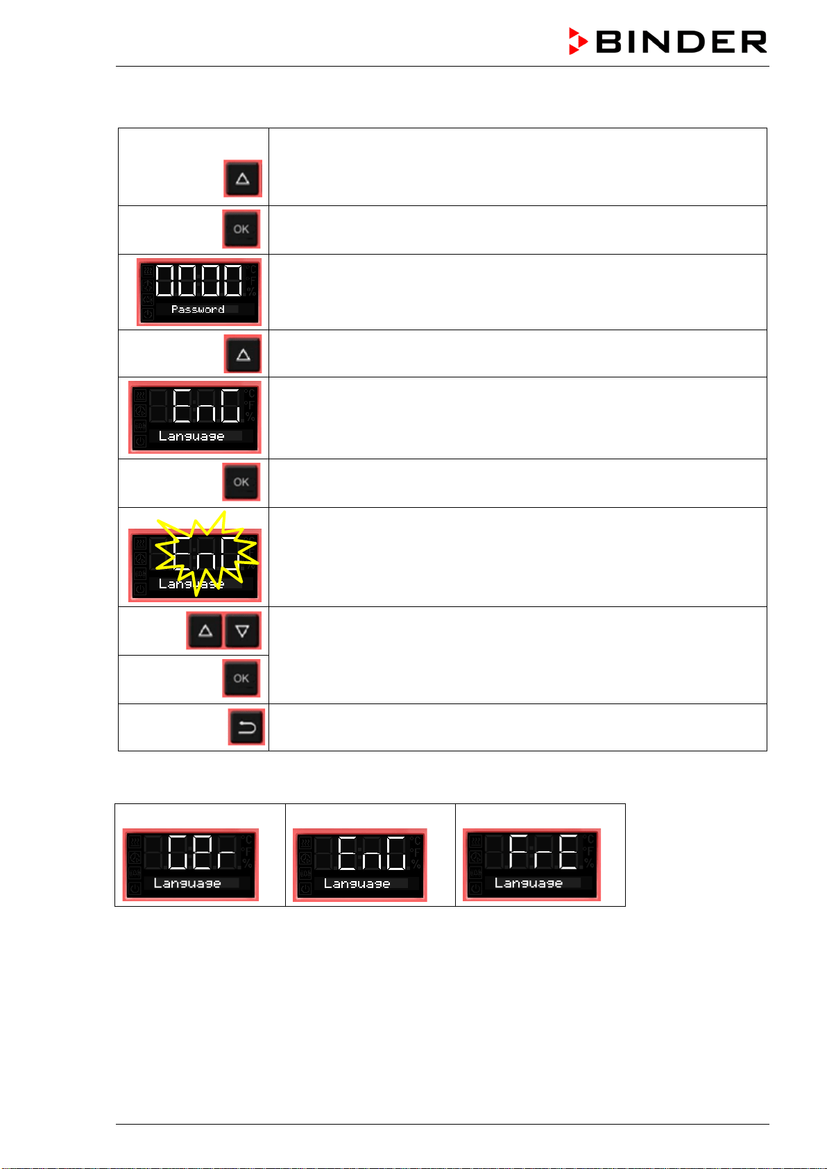
6.3 Setting the menu language
From Normal display
without fan 5x
with fan 6x
with the arrow-up button to the user menu
Confirm with OK.
Enter the password (factory setting: 00 00)
and confirm each entry with OK.
4 x
with the arrow-up button to the language setting menu.
The current menu language is shown.
Press OK to select the menu language.
The setting flashes.
Select the setting with the arrow buttons
and confirm with OK.
2x
Back to Normal display.
There are the following options:
German:
English:
French:
BD / BF / ED / FD / FED (E3.1) 03/2019 page 24/106
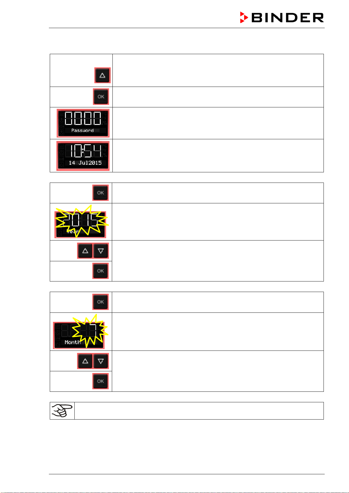
6.4 Setting date and time
From Normal display
without fan 5x
with fan 6x
with the arrow-up button to the user menu
Confirm with OK.
Enter the password (factory setting: 00 00)
and confirm each entry with OK.
The current date is shown.
Press OK to set the year.
The setting flashes.
Enter the year with the arrow buttons (any setting)
and confirm with OK.
Press OK to set the month.
The setting flashes.
Enter the month with arrow buttons (1 to 12)
and confirm with OK.
Without the optional real time clock, these settings must be repeated when the power supply is
interrupted..
BD / BF / ED / FD / FED (E3.1) 03/2019 page 25/106
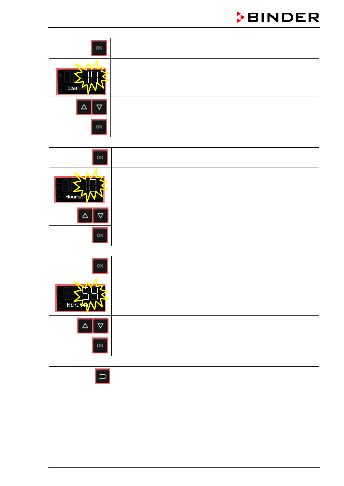
Press OK to set the day.
The setting flashes.
Enter the day with arrow buttons (1 to 31)
and confirm with OK.
Press OK to set the hour.
The setting flashes.
Enter the hour with arrow buttons (0 to 23)
and confirm with OK.
Press OK to set the minute.
The setting flashes.
Enter the minute with arrow buttons (0 to 59)
and confirm with OK.
2x
Back to Normal display.
BD / BF / ED / FD / FED (E3.1) 03/2019 page 26/106
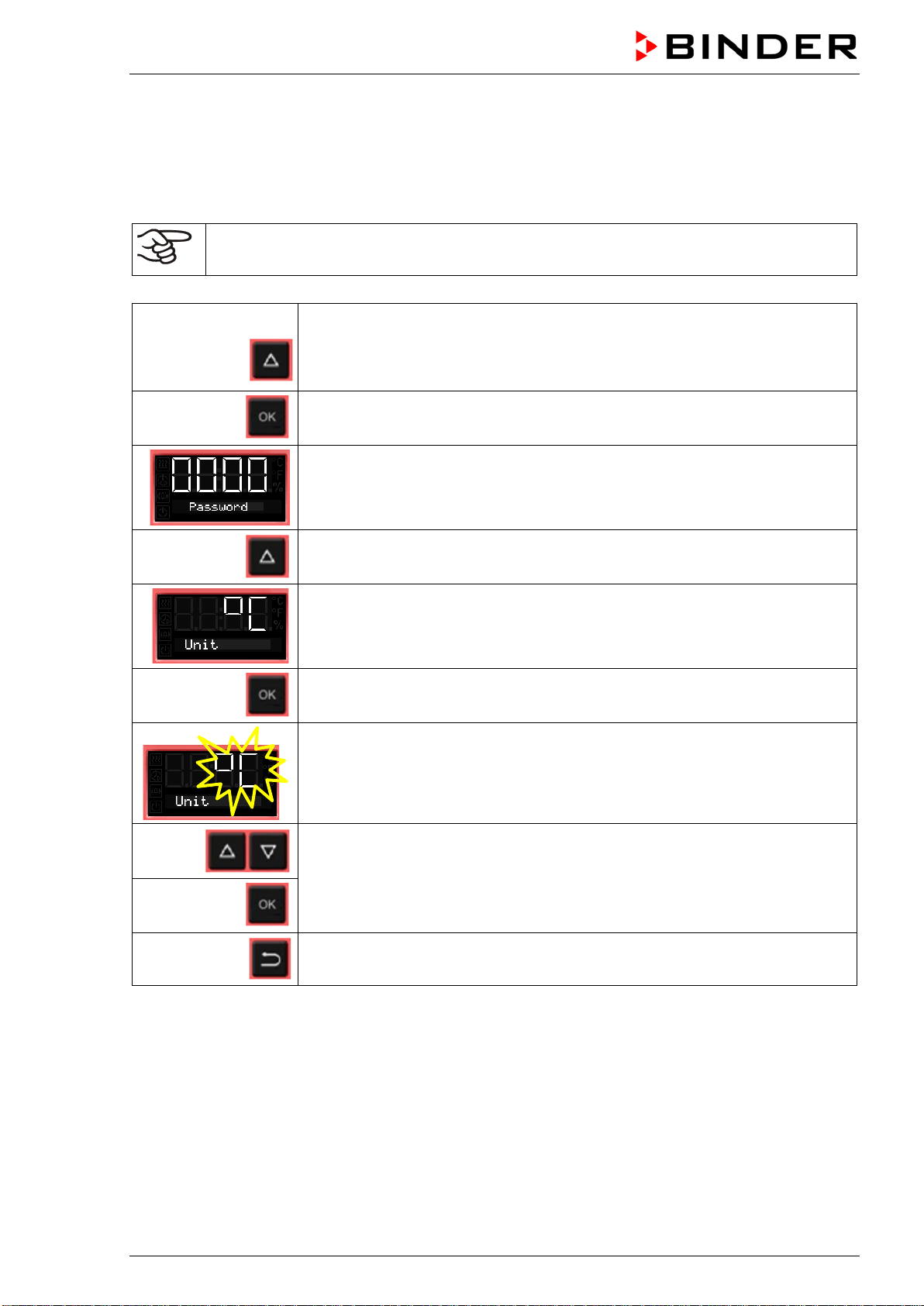
6.5 Selecting the temperature unit
You can chose between degrees Celsius °C and degrees Fahrenheit °F.
If the unit is changed, the temperature set-point and limits are converted accordingly.
Also when specifying the ramp function (see chap. 9) this setting is accordingly taken as the basis.
C = degrees Celsius
F= degrees Fahrenheit
0 °C = 31°F
100 °C = 212°F
Conversion:
[Value in °F] = [Value in °C] ∗ 1.8 + 32
From Normal display
without fan 5x
with fan 6x
with the arrow-up button to the user menu
Confirm with OK.
Enter the password (factory setting: 00 00)
and confirm each entry with OK.
With the arrow-up button to the temperature unit selection menu.
The current temperature unit is shown.
Press OK to select the temperature unit.
The setting flashes.
Select the setting with arrow buttons
and confirm with OK.
2x
Back to Normal display.
BD / BF / ED / FD / FED (E3.1) 03/2019 page 27/106
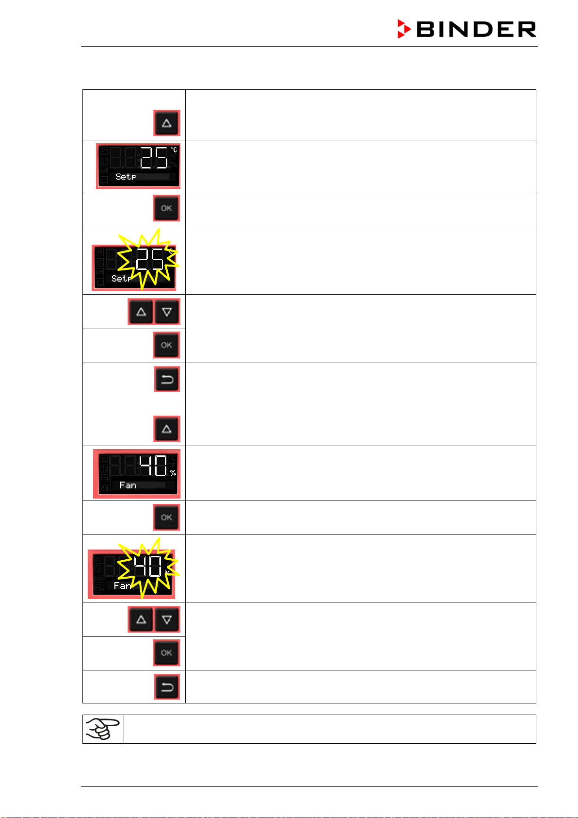
6.6 Set-point entry for temperature and fan speed
From Normal display
with the arrow-up button to the Set-point entry menu.
The current temperature set-point is displayed.
Press OK to enter the temperature set-point.
The temperature set-point flashes.
Enter the temperature set-point with arrow buttons with an accuracy of a tenth
of a degree (BD, BF) or of one degree (ED, FD, FED)
and confirm with OK.
Back to Normal display.
or
with chambers with adjustable fan speed (BF, FED):
go on to enter the fan speed.
The fan speed set-point is displayed.
Press OK to enter the fan speed
The fan speed set-point flashes
Adjust the fan speed in steps of 10 % with arrow buttons
and confirm with OK.
Back to Normal display.
Check and/or adjust the safety controller following any changes of the set-point (chap. 7).
BD / BF / ED / FD / FED (E3.1) 03/2019 page 28/106
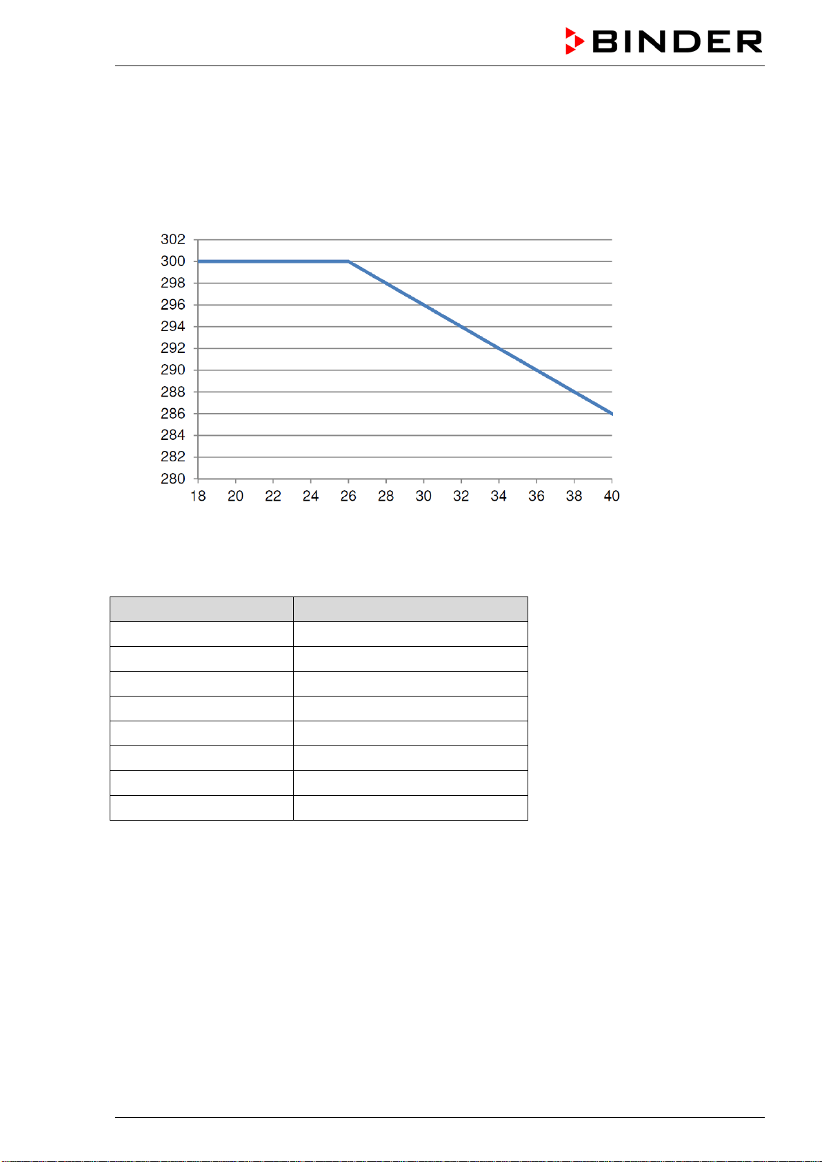
6.6.1 Set-point entry for temperature in two-door chambers (ED, FD, FED 720)
With two-door chambers (ED, FD, FED 720) the maximum adjustable temperature set-point depends on
the ambient temperature:
• Range from 18 °C up to 26 °C: maximum temperature set-point: 300 °C
• Range from above 26 °C up to 40 °C: maximum temperature set-point decreasing with increasing
ambient temperature
Temperature set-point [ °C ]
Ambient temperature [ °C ]
Figure 10: Maximum temperature set-point depending on the ambient temperature
Ambient temperature Maximum temperature set-point
18 °C up to 26 °C 300 °C
28 °C 298 °C
30 °C 296 °C
32 °C 294 °C
34 °C 292 °C
36 °C 290 °C
38 °C 288 °C
40 °C 286 °C
This ensures the maximum lifetime of the controller.
BD / BF / ED / FD / FED (E3.1) 03/2019 page 29/106
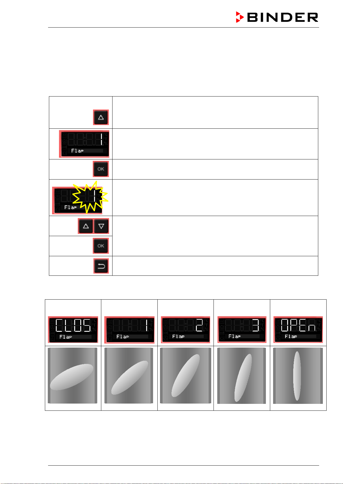
6.7 Adjusting the air flap position
Opening the air flap in the exhaust duct serves to adjust the air change.
The position of the air flap in the exhaust duct serves to adjust the fresh air entry. With the open the air
flap, fresh air can enter through the fresh air tube. For chambers with fan, fan operation will increase
fresh air entry.
If the air flap is completely open, the spatial temperature accuracy can be negatively influenced.
From Normal display
without fan 2x
with fan 3x
with the arrow-up button to the Adjusting the air flap position menu.
The current air flap position is shown.
Press OK to select the air flap position.
The setting flashes.
Select the position with arrow buttons
and confirm with OK.
Back to Normal display.
There are the following options:
Air flap
closed
Air flap slightly
opened
Air flap half opened
Air flap almost
open
Air flap open
The setting can be done in steps of 15°.
BD / BF / ED / FD / FED (E3.1) 03/2019 page 30/106
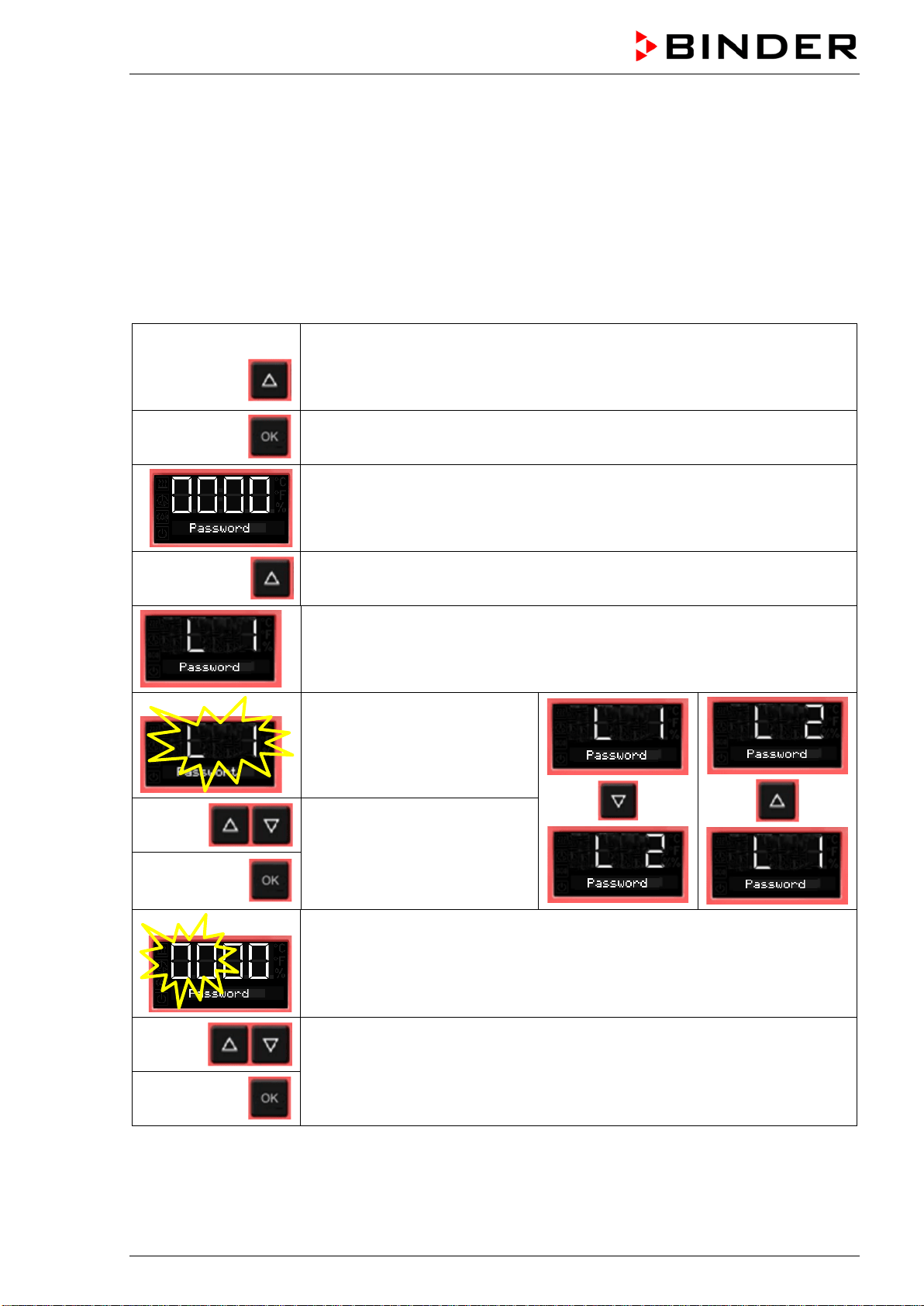
6.8 Changing the passwords for user level and general controller functions
In this menu you can change the passwords for access to the user menu and to all controller functions.
You can set two passworts for different access levels:
L1 (level 1): The password enables access control to the user level
L2 (level 2): The password enables access control to all controller functions
Factory setting for both passwords is 00 00 (no password assigned).
As soon as a password has been assigned, access to the respective functions is blocked and only avail-
able after enering the correct password.
From Normal display
without fan 5x
with fan 6x
with the arrow-up button to the user menu
Confirm with OK.
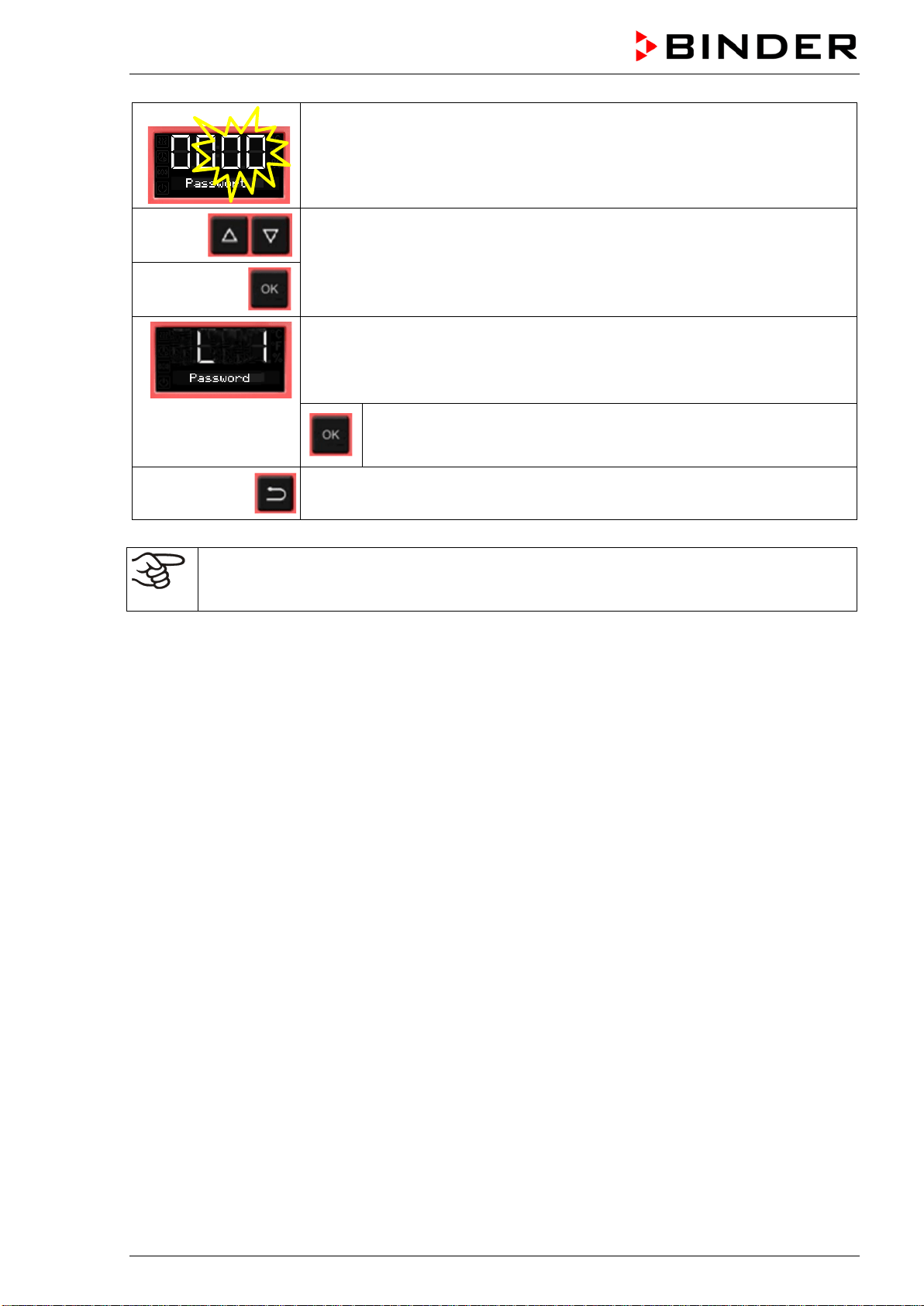
Enter the password (factory setting: 00 00)
and confirm each entry with OK.
2 x
With the arrow-up button to the password setting menu.
Password L1 for access to the user level.
Confirm with OK.
The current password level L1
is shown. The setting flashes.
You can change beween L1
and L2 with arrow buttons.
Select the setting with arrow
buttons (if desired)
and confirm with OK.
The current password for the selected password level is shown. The left two
digits are flashing.
Enter the desired numbers with arrow buttons,
confirm with OK and go on.
BD / BF / ED / FD / FED (E3.1) 03/2019 page 31/106
The right two digits of the password are flashing.
Enter the desired numbers with arrow buttons
and confirm with OK.
The modified password (L1 or L2 depending on the selection) is shown
(example: L1).
If you want to change beween L1 and L2, confirm with OK. Thereaf-
ter you can change to the other password level and also modify the
password.
2x
Back to Normal display.
Keep in mind any modification of the password. There is no access to the user menu without
the correct password L1. Without the correct password L2 access control to all controller func-
tions is blocked.
BD / BF / ED / FD / FED (E3.1) 03/2019 page 32/106
7. Overtemperature protection
7.1 Overtemperature protective device (class 1)
The chambers are regularly equipped with an overtemperature protective device (safety device class 1
acc. to DIN 12880:2007). It serves to protect the chamber, its environment and the contents against ex-
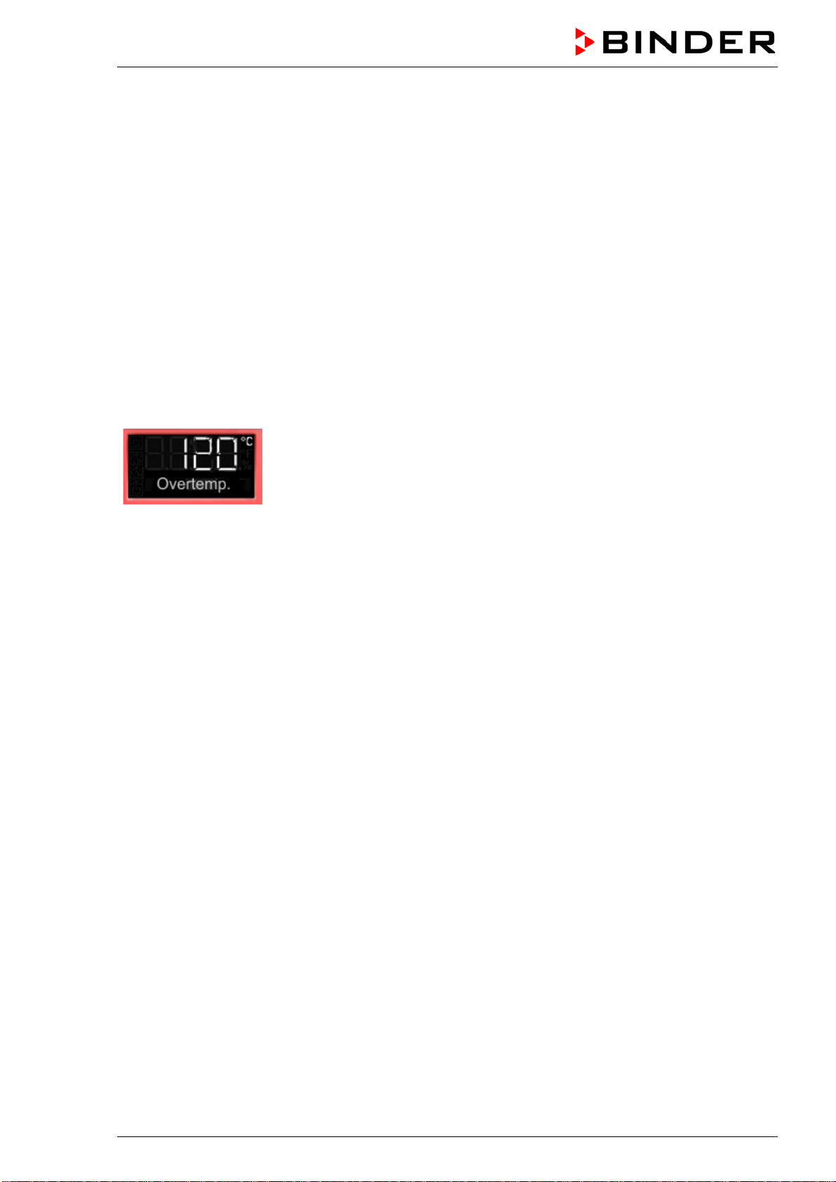
ceeding the maximum permissible temperature. When a defined temperature is reached, which is approx.
by 20 °C to 30 °C above the chamber’s nominal temperature, the overtemperature protective device turns
off the heating.
Cut-off temperature values:
BD, BF: 120 °C
ED 260: 320 °C
ED 56, ED 115, FD 56, FED 56: 330 °C
FD 115, FD 260, FED 115, FED 260: 350 °C
The message “Overtemperature” is displayed on the controller.
If the overtemperature protective device class 1 has turned off the heating, proceed as follows:
• Disconnect the chamber from the power supply for at least 10 seconds (pull the power plug).
• If appropriate, have an expert examine and rectify the cause of the fault.
• Let the chamber cool down
• Restart the chamber.
As soon as the inner chamber temperature after restart is below the defined cut-off temperature of the
overtemperature protective device class 1, the alarm message is deleted automatically.
Reset temperature values:
BD, BF: 90 °C
ED 260: 220 °C
ED 56, ED 115, FD 56, FED 56: 230 °C
FD 115, FD 260, FED 115, FED 260: 250 °C

BD / BF / ED / FD / FED (E3.1) 03/2019 page 33/106
7.2 Safety controller
The chambers are regularly equipped with an adjustable electronic safety controller. It serves to protect
the chamber, its environment and the contents against exceeding the maximum permissible temperature.
Please observe the DGUV guidelines 213-850 on safe working in laboratories (formerly BGI/GUV-I 850-0,
BGR/GUV-R 120 or ZH 1/119, issued by the employers’ liability insurance association) (for Germany).
Depending on the chamber type the safety controller acts as an over temperature safety device class 2
(“temperature limiter”) or class 3.1 (“temperature protection”) acc. to DIN 12880:2007.
Check the setting regularly and adjust it following any changes of the set-point.
• Safety controller class 2 (“temperature limiter”) with ED, FD and FED
The safety controller class 2 limits the temperature inside the chamber to the entered safety controller
set-point. In the event of a fault (if this maximum temperature is exceeded) the safety controller com-
pletely turns off the heating until manual reset. This status is reported visually by an alarm message
and, in case of the option audible alarm with activated buzzer (chap. 7.6) additionally by the buzzer
sounding.
If the safety controller class 2 has turned off the heating, we recommend proceeding as follows:
• Disconnect the chamber from the power supply.
• Have an expert examine and rectify the cause of the fault.
• Restart the chamber
• Reset the alarm message
• Safety controller class 3.1 (“temperature protection”) with BD and BF
The safety controller class 3.1 limits the temperature inside the chamber to the entered safety control-
ler set-point. In the event of a fault (if this maximum temperature is exceeded), it takes over the control
to this value. This status is reported visually by an alarm message and, in case of the option audible
alarm with activated buzzer (chap. 7.6) additionally by the buzzer sounding.
The safety controller keeps control of the chamber until the chamber temperature cools down below
the safety controller set-point value.
If the safety controller class 3.1 has taken over control, we recommend proceeding as follows:
• Disconnect the chamber from the power supply.
• Have an expert examine and rectify the cause of the fault.
• Restart the chamber
• Reset the alarm message
Function check:
Check the safety controller at appropriate intervals for its functionality. It is recommended that the author-
ized operating personnel should perform such a check, e.g., before starting a longer work procedure.
BD / BF / ED / FD / FED (E3.1) 03/2019 page 34/106
7.3 Setting the safety controller set-point
A limit temperature is entered as the safety controller set-point , i.e. the absolute maximum permitted
temperature value.
Example: Temperature set-point 45 °C, safety controller set-point 50 °C.
Regularly check the safety controller setting relating to the entered temperature set-point
Set the safety controller set-point by approx. 2 °C to 5 °C above the desired temperature set-
point.
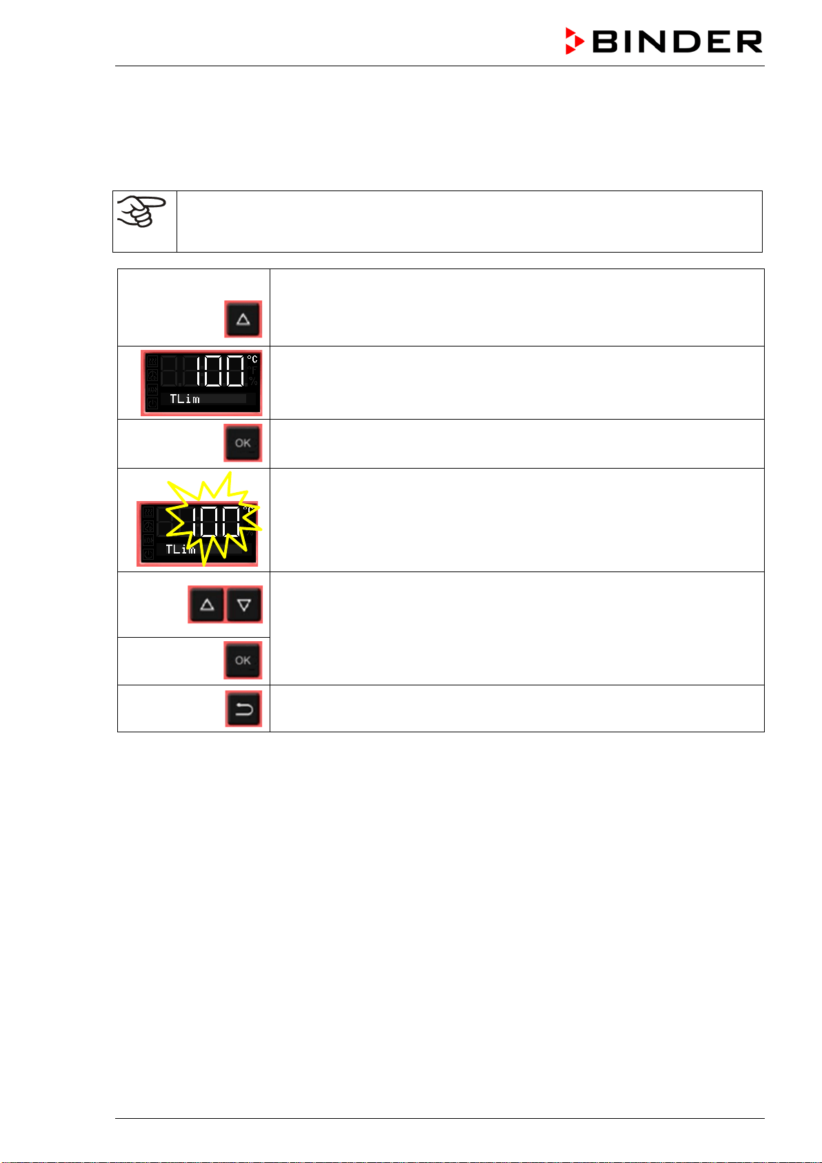
From Normal display
without fan 4x
with fan 5x
with the arrow-up button to the Safety controller set-point setting menu.
The current safety controller set-point is shown
(class 2 “temperature limiter” or class 3.1 “temperature protection” depending
on the chamber type).
Press OK to enter the safety controller set-point.
The safety controller set-point flashes.
Enter the safety controller set-point with arrow buttons:
10 °C up to 100 °C (with an accuracy of a tenth of a degree) with BD, BF
10 °C up to 300 °C (with an accuracy of one degree) with ED, FD, FED
and confirm with OK.
Back to Normal display.
BD / BF / ED / FD / FED (E3.1) 03/2019 page 35/106
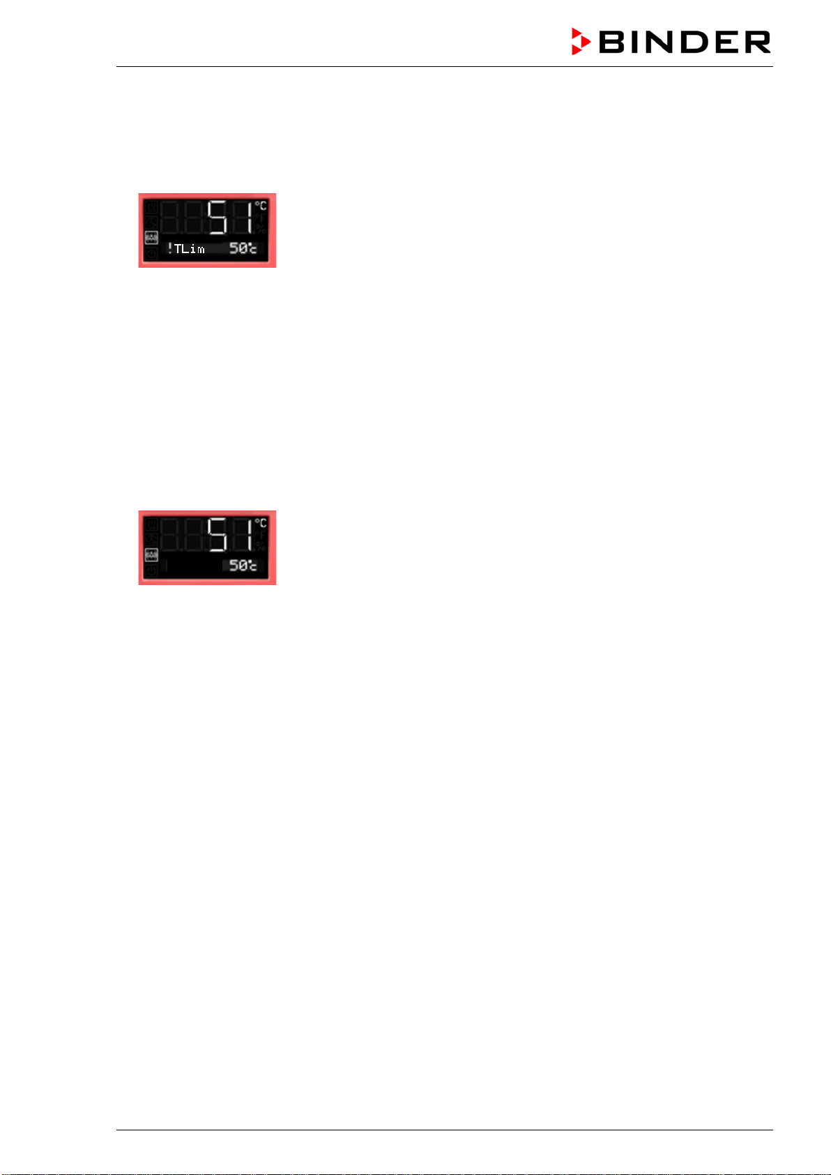
7.4 Alarm message and proceeding in case of an alarm
The alarm icon flashes in the display. In case of the option audible alarm with activated buzzer (chap. 7.6)
the buzzer sounds.
• Safety controller class 2 (“temperature limiter”)
The alarm icon flashes in the display. In case of the option audible alarm with activated buzzer (chap.
7.6) the buzzer sounds.
The heating turns off.
Resetting the alarm:
With option audible alarm with activated buzzer: Mute the buzzer pressing the OK button.
As soon as the inner chamber temperature has cooled down below the safety controller set-point, the
alarm icon is lit permanently. You can reset the alarm message on the controller. To do this, reset the
alarm message in the safety controller menu with the OK button. The heating is released and tem-
perature control is resumed by the controller.
• Safety controller class 3.1 (“temperature protection”)
The alarm icon flashes in the display. In case of the option audible alarm with activated buzzer (chap.
7.6) the buzzer sounds.
The heating turns off.
Resetting the alarm:
With option audible alarm with activated buzzer: Mute the buzzer pressing the OK button.
As soon as the inner chamber temperature has cooled down below the safety controller set-point,
You can reset the alarm message in the safety controller menu with the OK button, The heating is re-
leased and temperature control is resumed by the controller.
Note:
When the safety controller class 2 or class 3.1 had been activated, you should disconnect the chamber
from the power supply and have an expert examine and rectify the cause of the fault.
7.5 Function check
Check the temperature safety device class 2 or class 3.1 at appropriate intervals for its functionality. It is
recommended that the authorized operating personnel should perform such a check, e.g., before starting
a longer work procedure
!TProt
BD / BF / ED / FD / FED (E3.1) 03/2019 page 36/106
7.6 Disconnectable audible over-temperature alarm (option)
This option permits activating an audible signal:
If the buzzer is activated, an audible signal sounds when the limit temperature set at the safety controller
is exceeded. This happens in addition to the alarm message on the controller display.
Turning off the audible alarm does not influence the safety controller’s function.
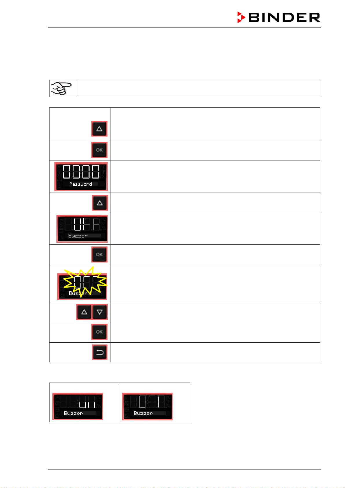
From Normal display
without fan 5x
with fan 6x
with the arrow-up button to the user menu
Confirm with OK.
Enter the password (factory setting: 00 00)
and confirm each entry with OK.
5 x
With the arrow-up button to the alarm buzzer setting menu
The current setting is shown.
Press OK to select the alarm buzzer setting
The setting flashes.
Select the setting with arrow buttons
and confirm with OK.
Back to Normal display.
There are the following options
Alarm buzzer On
Alarm buzzer Off
BD / BF / ED / FD / FED (E3.1) 03/2019 page 37/106
8. Timer functions
8.1 Selecting the timer function
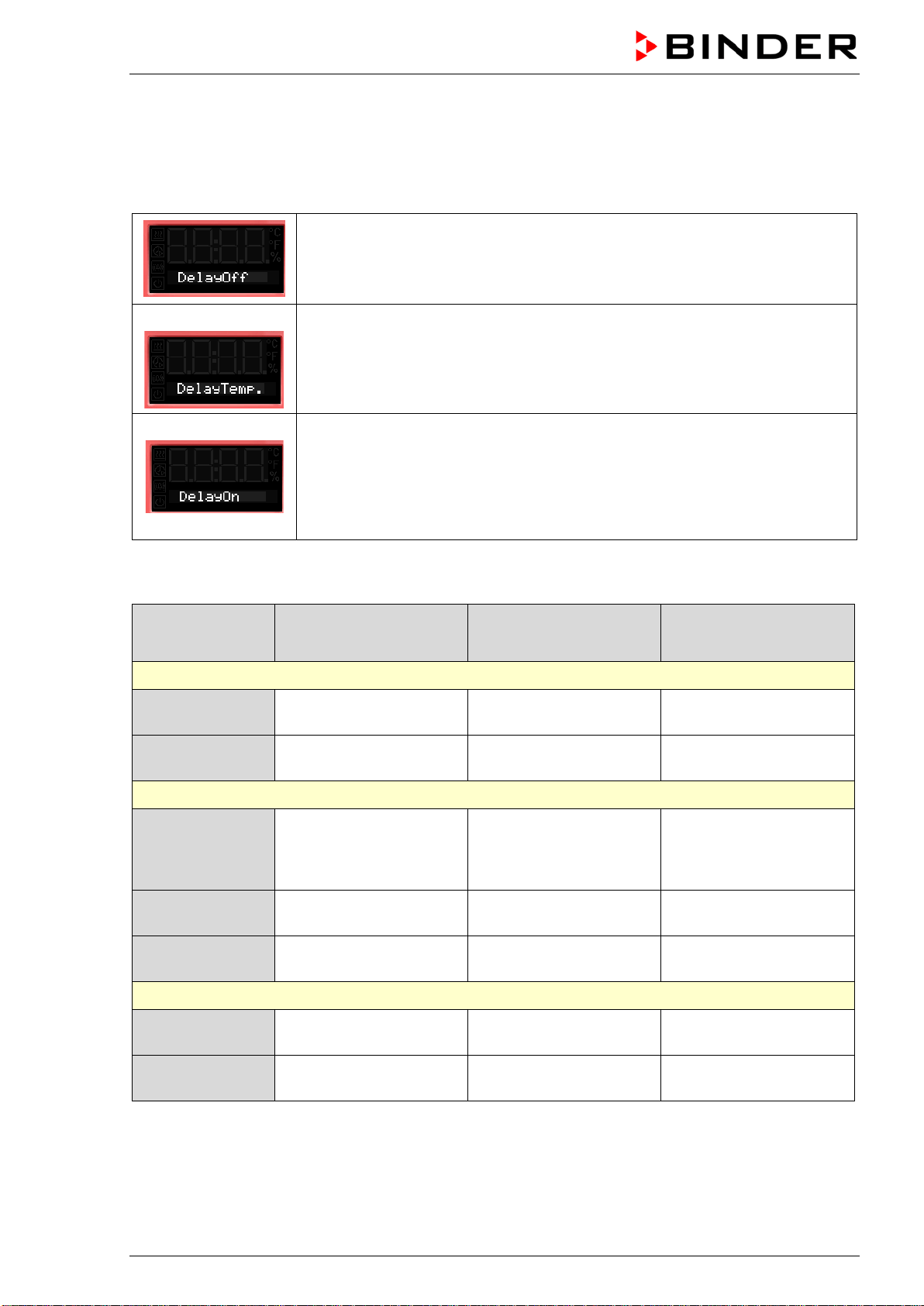
There are up to three 3 timer functions:
Timer function “Delayed Off”
The selected timer run-time immediately starts running down.
When the timer expires the heating turns off. Chambers with fan: The fan may
continue working according to the selections made.
Timer function “Temperature dependent Delayed Off”
The selected timer run-time only starts running down, when the actual value
reached or exceeds the selected set-point. When the timer expires the heating
turns off. Chambers with fan: The fan may continue working according to the
selections made.
Timer function “Delayed On”
The selected timer run-time immediately starts running down, the heating turns
off. Chambers with fan: The fan may be working according to the selections
made.
When the timer expires the heating turns on and remains in continuous opera-
tion.
The chambers BD, ED and FD offer the timer function “Delayed Off”
The chambers BF and FED offer all the three timer functions.
Stage Heating
Fan (Chamber with
fixed fan speed: FD)
Fan (Chambers with
adjustable fan speed:
BF, FED)
Timer function “Delayed Off”
Timer running
Control to the
temperature set-point
On (100 %)
Rotation speed according
to fan speed set-point
After the timer
expired
Off
On (100 %) or Off
(0 %) acc. to selection
Rotation speed according
to setting of timer function
Timer function “Temperature dependent Delayed Off”
Possibly heating-
up phase until the
temperature set-
point is reached
Control to the
temperature set-point
---
Rotation speed according
to fan speed set-point
Timer running
Control to the
temperature set-point
---
Rotation speed according
to fan speed set-point
After the timer
expired
Off ---
Rotation speed according
to setting of timer function
Timer function “Delayed On”
Timer running
Off ---
Rotation speed according
to setting of timer function
After the timer
expired
Control to the
temperature set-point
---
Rotation speed according
to fan speed set-point
BD / BF / ED / FD / FED (E3.1) 03/2019 page 38/106
General information on the setting:
In the setting menus of the timer functions, it is always required to confirm all parameters with OK, other-
wise all entries made will be lost.
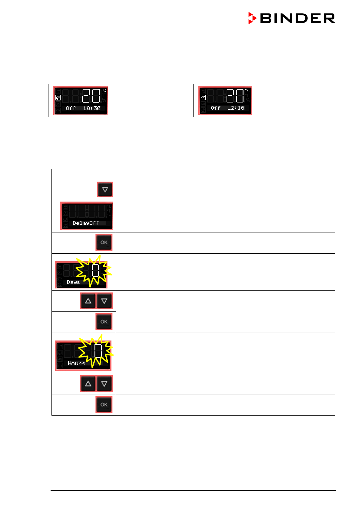
Timer run-time is set in days, hours, and minutes. If days have been entered, they are shown in the
controller display preceded by an underscore:
Setting:
0 days (not shown),
10 hours, 30 minutes
Setting:
2 days, 10 hours
(minutes not shown)
8.2 Timer function “Delayed Off”
8.2.1 Entry and activation of the timer run-time and fan setting
From Normal display
with the arrow-down button to the Timer function “Delayed Off” menu
(with connected USB device: press the arrow-down button twice)
Current Timer function “Delayed Off”
Confirm with OK and go on to enter the days of the timer run-time.
The current timer run-time (days) is shown. The day value flashes.
Enter the days of the timer run-time (0 up to 9)
confirm with OK
and go on to enter the hours of the timer run-time
The hour value flashes.
Enter the hours of the timer run-time (0 up to 23)
confirm with OK
and go on to enter the minutes of the timer run-time
BD / BF / ED / FD / FED (E3.1) 03/2019 page 39/106
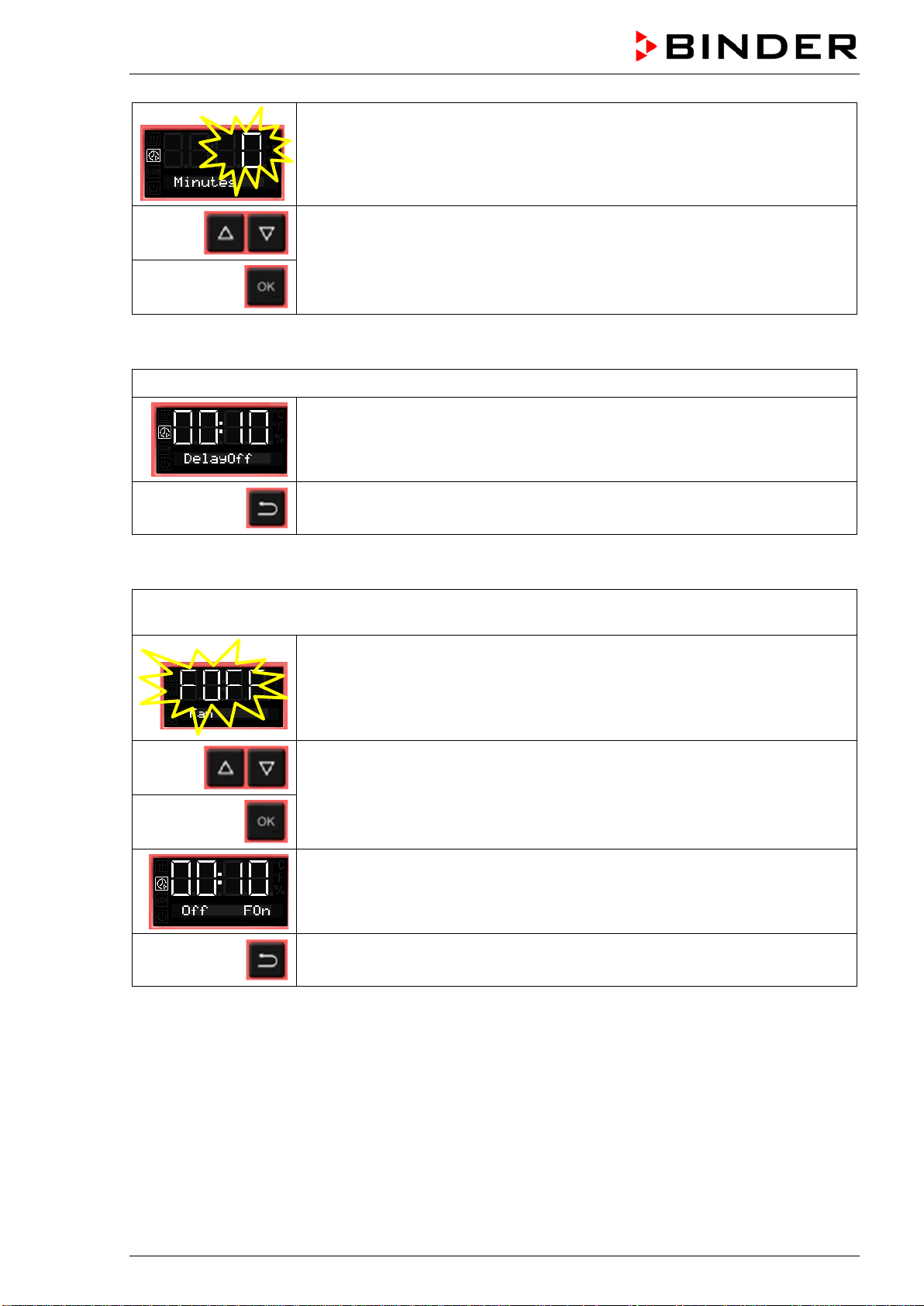
The minute value flashes.
Enter the minutes of the timer run-time (0 up to 59)
and confirm with OK.
Chambers without fan (BD, ED):
The timer function “Delayed Off” is activated
Back to Normal display.
Chamber with fixed fan speed (FD):
Select whether the fan shall operate or not after the timer has expired
The current setting of the fan operation is shown
Select fan operation: On (100 %) or Off (0 %)
and confirm with OK.
The timer function “Delayed Off” is activated
Back to Normal display.
BD / BF / ED / FD / FED (E3.1) 03/2019 page 40/106
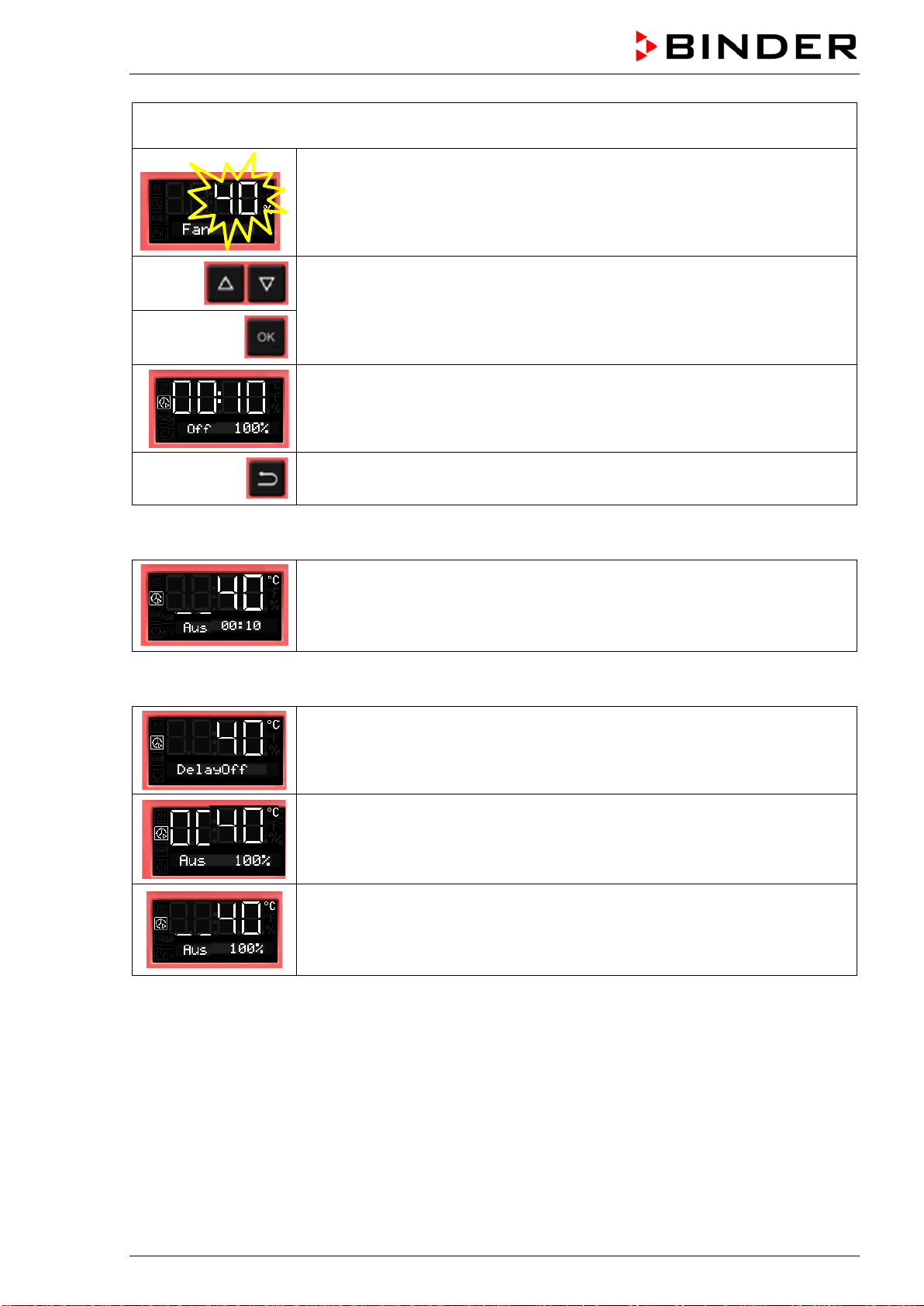
Chambers with adjustable fan speed (BF, FED):
Enter the fan speed set-point valid for the time after the timer has expired.
The current fan speed set-point is shown
Enter the fan speed in steps of 10 %
0 % and 40 % up to 100 %
and confirm with OK.
The timer function “Delayed Off” is activated
Back to Normal display.
Normal display during timer operation with timer function „Delayed Off“
The timer run-time until turning off the heating is running down.
Normal display after the timer has expired:
Chambers without fan (BD, ED):
Timer function “Delayed Off”.
The timer has expired. The heating is off.
Chamber with fixed fan speed (FD):
Timer function “Delayed Off”.
The timer has expired. The heating is off.
The fan is operating (On) or not (Off), as selected
Chambers with adjustable fan speed (BF, FED):
Timer function “Delayed Off”.
The timer has expired. The heating is off.
The fan operates with the selected fan speed.
When the timer has expired, the heating is off. The chamber cools down to ambient temperature.
To restart the chamber you need to turn off the timer function (chap. 8.2.2)
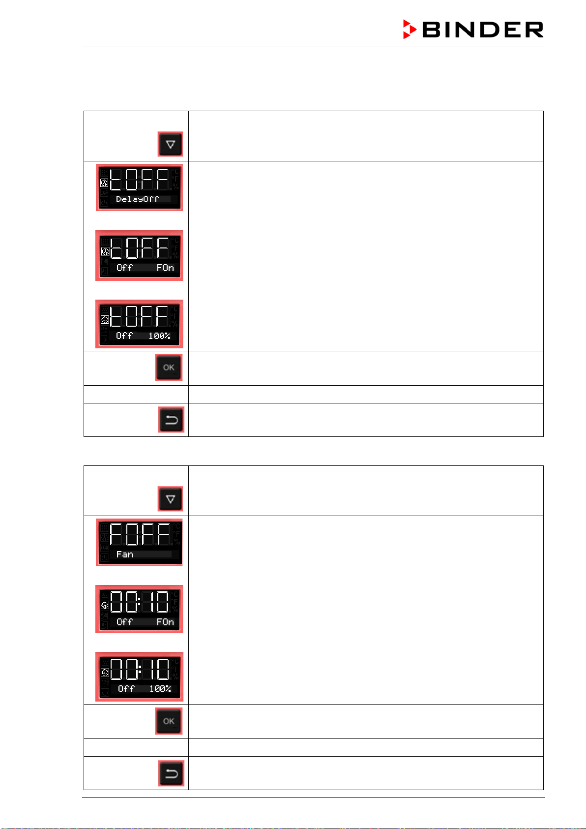
8.2.2 Turning off the timer function or changing the settings
To turn off the timer function “Delayed Off” during the time when it is still running, set all time values
(days, hours, minutes) to zero in the according menu (terminating the timer function). As long as the timer
is running, the timer function settings can be subsequently modified in this menu.
After the timer expired you can turn off the timer function by pressing the OK button. Alternatively you can
also set the time to zero in the according menu.
BD / BF / ED / FD / FED (E3.1) 03/2019 page 41/106
Turning off the timer function when the timer has expired
In Normal display press the OK button.
Alternatively you can set the time to zero:
From Normal display
with the arrow-down button to the Timer function “Delayed Off” menu
(with connected USB device: press the arrow-down button twice)
Chambers without fan (BD, ED):
Timer function “Delayed Off”, the timer has expired. The heating is off.
or
Chamber with fixed fan speed (FD):
Timer function “Delayed Off”, the timer has expired. The heating is off.
The fan is operating (On) or not (Off), as selected
or
Chambers with adjustable fan speed (BF, FED):
Timer function “Delayed Off”, the timer has expired. The heating is off.
The fan operates with the selected fan speed.
Confirm the timer function “Delayed Off” with OK
see chap. 8.2.1 Set all time values to zero
2x
Back to Normal display.
Changing or terminating the timer function when the timer is running:
From Normal display
with the arrow-down button to the Timer function “Delayed Off” menu
(with connected USB device: press the arrow-down button twice)
Chambers without fan (BD, ED):
Timer function „Delayed Off“, the timer is running.
or
Chamber with fixed fan speed (FD):
Timer function “Delayed Off”, the timer is running.
or
Chambers with adjustable fan speed (BF, FED):
Timer function “Delayed Off”, the timer is running.
Confirm the timer function “Delayed Off” with OK
see chap. 8.2.1 Modify the time values or set them to zero to terminate the timer function
2x
Back to Normal display.
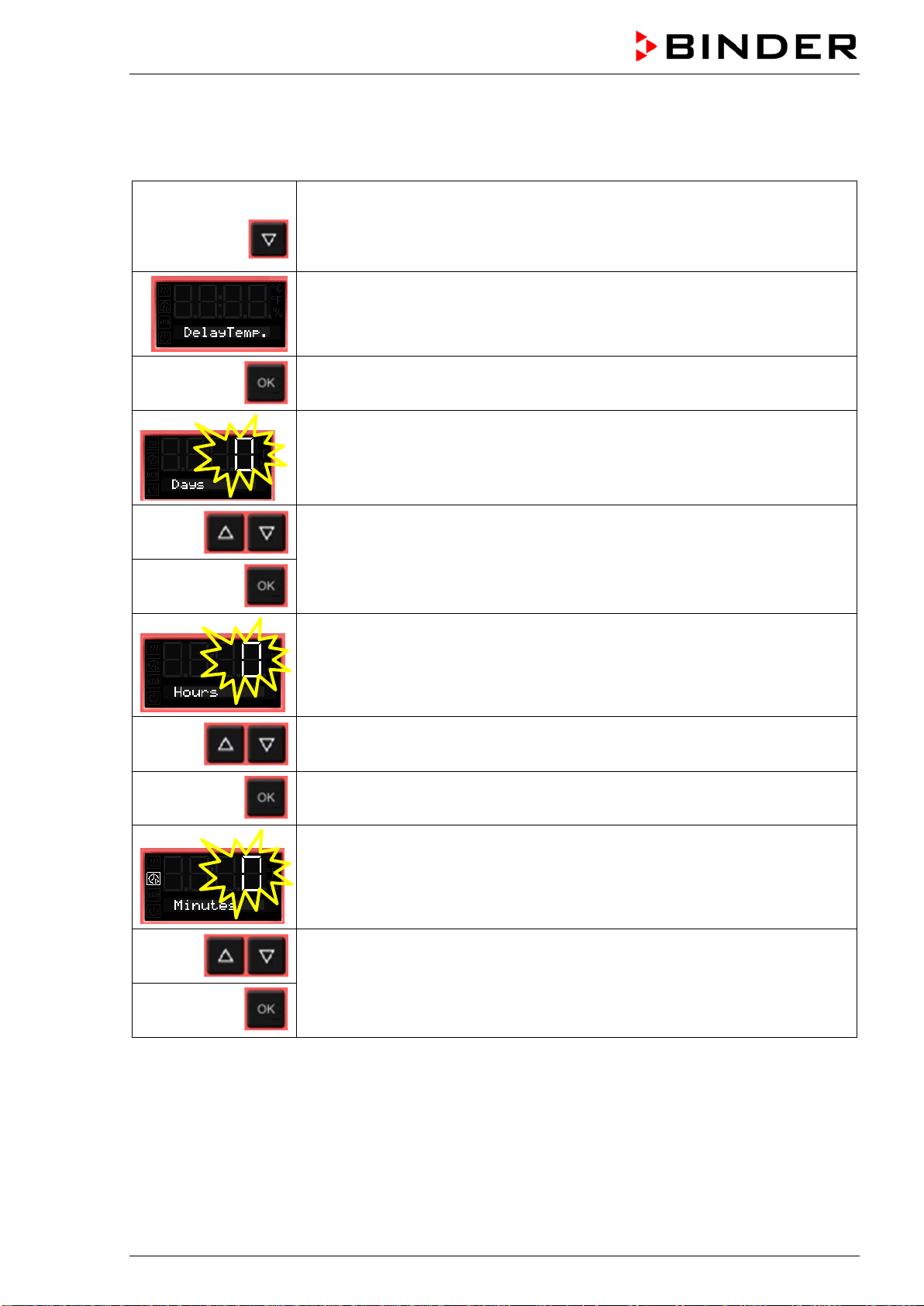
BD / BF / ED / FD / FED (E3.1) 03/2019 page 42/106
8.3 Timer function “Temperature dependent Delayed Off” (BF, FED)
8.3.1 Entry and activation of the timer run-time, fan setting and set-point entry
From Normal display
3 x
with the arrow-down button to the Timer function “Temperature dependent
Delayed Off” menu
(with connected USB device: press the arrow-down button 4 times)
Current Timer function “Temperature dependent Delayed Off”
Confirm with OK and go on to enter the days of the timer run-time.
The current timer run-time (days) is shown. The day value flashes.
Enter the days of the timer run-time (0 up to 9)
confirm with OK
and go on to enter the hours of the timer run-time
The hour value flashes.
Enter the hours of the timer run-time (0 up to 23)
confirm with OK
and go on to enter the minutes of the timer run-time
The minute value flashes.
Enter the minutes of the timer run-time (0 up to 59)
confirm with OK
and go on to enter the temperature set-point
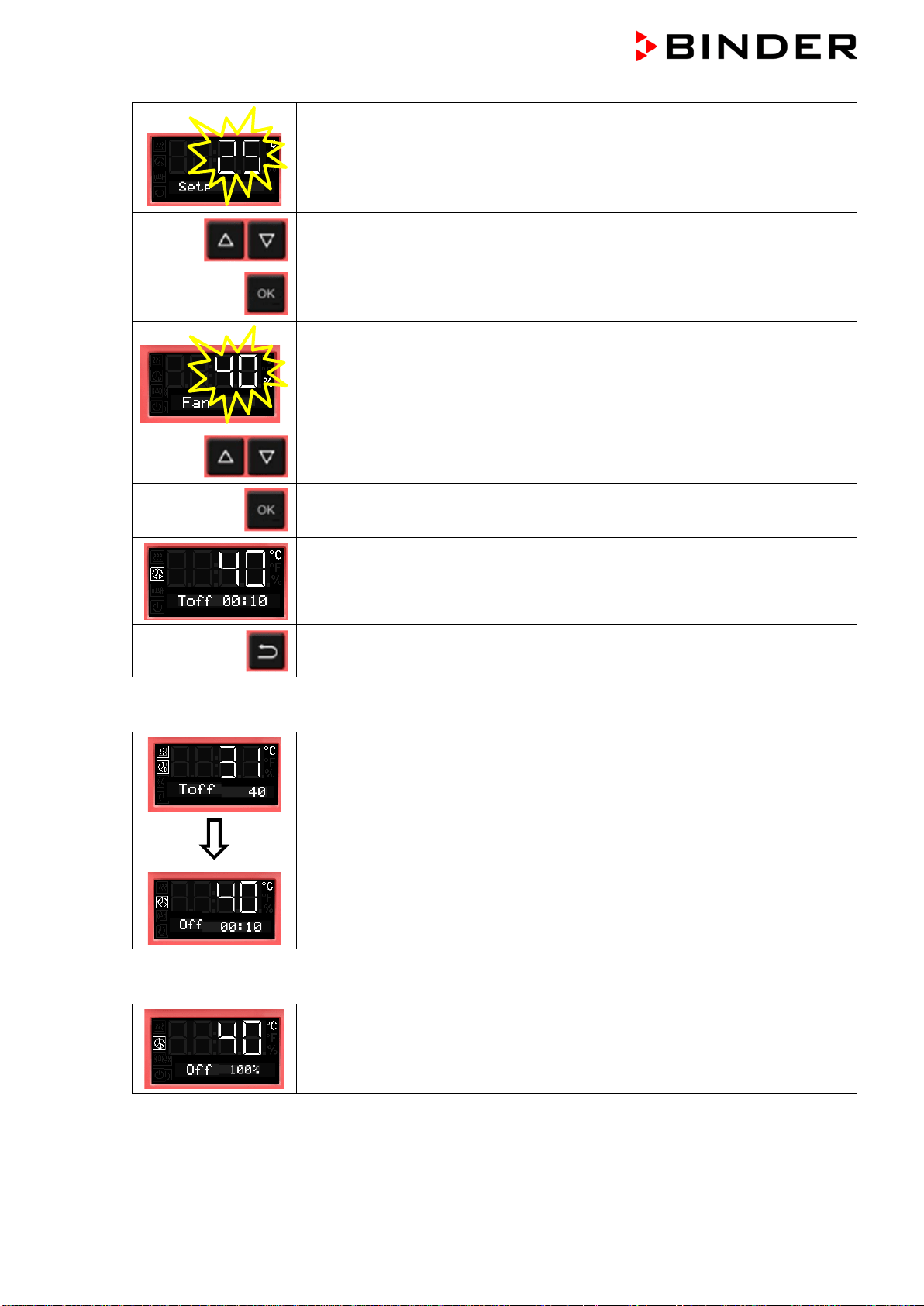
BD / BF / ED / FD / FED (E3.1) 03/2019 page 43/106
The temperature set-point flashes.
When the set-point is reached, the timer starts running down.
Enter the temperature set-point,
confirm with OK and go on to enter the fan speed set-point valid for the time
after the timer has expired
The current fan speed is shown
Enter the fan speed in steps of 10 %
0 % and 40 % up to 100 %
and confirm with OK.
The timer function “Temperature dependent Delayed Off” is activated
Back to Normal display.
Normal display during timer operation with timer function „Temperature dependent Delayed Off“
Normal display while the timer is running
If the entered set-point exceeds the current actual value, the chamber heats
up.
As soon as the set-point is reached or exceeded, the timer starts running down
Normal display during the timer run-time.
The timer run-time until turning off the heating (and possibly the fan) is running.
Normal display after the timer has expired:
Timer function “Temperature dependent Delayed Off”.
The timer has expired. The heating is off. The fan operates with the selected
fan speed.
When the timer has expired, the heating is off. The chamber cools down to ambient temperature.
To restart the chamber you need to turn off the timer function (chap. 8.3.2).
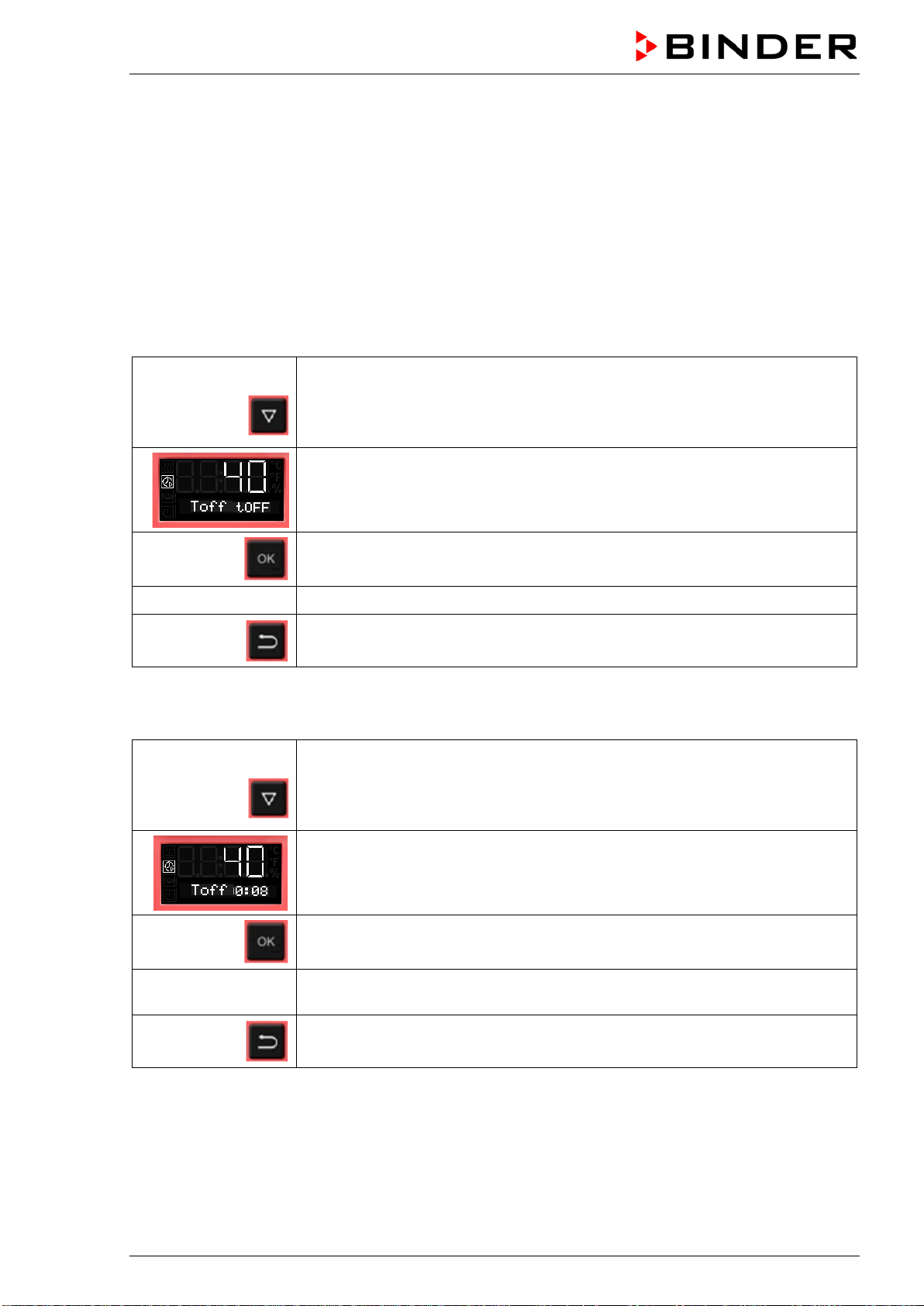
BD / BF / ED / FD / FED (E3.1) 03/2019 page 44/106
8.3.2 Turning off the timer function or changing the settings
To turn off the timer function “Temperature dependent Delayed Off” during the time when it is still running,
set all time values (days, hours, minutes) to zero in the according menu (terminating the timer function).
As long as the timer is running, the timer function settings can be subsequently modified in this menu.
After the timer expired you can turn off the timer function by pressing the OK button. Alternatively you can
also set the time to zero in the according menu.
Turning off the timer function when the timer has expired
In Normal display press the OK button.
Alternatively you can set the time to zero:
From Normal display
3 x
with the arrow-down button to the Timer function “Temperature dependent
Delayed Off” menu
(with connected USB device: press the arrow-down button 4 times)
Timer function “Temperature dependent Delayed Off”, the timer has expired
Confirm the timer function “Temperature dependent Delayed Off” with OK
see chap. 8.3.1 Set all time values to zero
Back to Normal display
Changing or terminating the timer function when the timer is running:
From Normal display
3 x
with the arrow-down button to the Timer function “Temperature dependent
Delayed Off” menu
(with connected USB device: press the arrow-down button 4 times)
Timer function “Temperature dependent Delayed Off”, the timer is running
Confirm the timer function “Temperature dependent Delayed Off” with OK
see chap. 8.3.1
Modify the time values or set all time values to zero to terminate the timer func-
tion
Back to Normal display
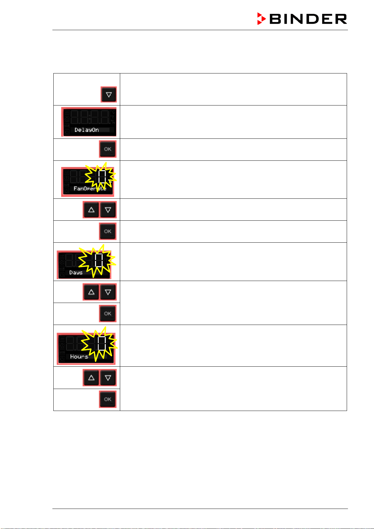
BD / BF / ED / FD / FED (E3.1) 03/2019 page 45/106
8.4 Timer function “Delayed On” (BF, FED)
8.4.1 Entry and activation of the timer run-time and fan setting
From Normal display
2 x
with the arrow-down button to the Timer function “Delayed On” menu
(with connected USB device: press the arrow-down button 3 times)
Current timer function “Delayed On”
Confirm with OK and go on to enter the fan speed set-point valid during the
time the timer is running
The current fan speed set-point is shown
Enter the fan speed in steps of 10 %
0 % and 40 % up to 100 %
Confirm with OK and go on to enter the days of the timer run-time.
The current timer run-time (days) is shown. The day value flashes.
Enter the days of the timer run-time (0 up to 9)
confirm with OK
and go on to enter the hours of the timer run-time
The hour value flashes.
Enter the hours of the timer run-time (0 up to 23),
confirm with OK
and go on to enter the minutes of the timer run-time
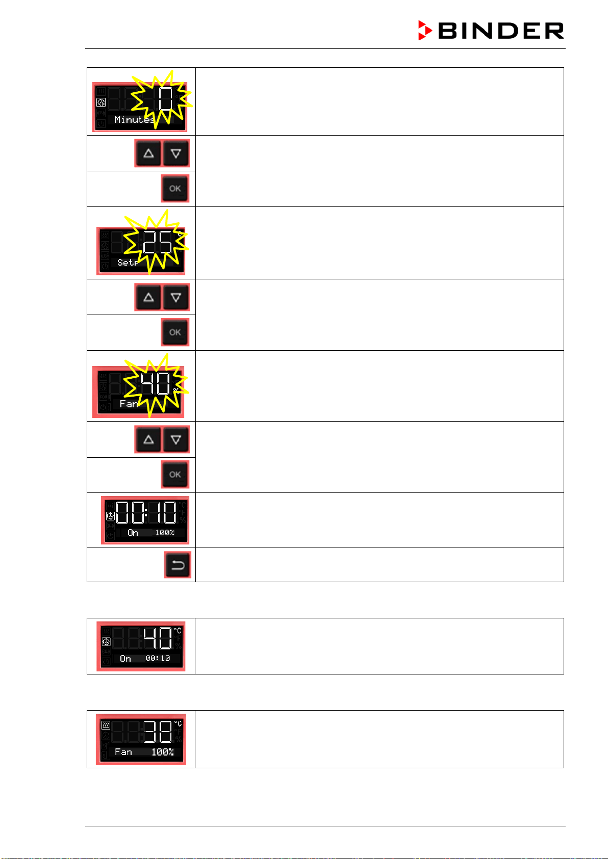
BD / BF / ED / FD / FED (E3.1) 03/2019 page 46/106
The minute value flashes.
Enter the minutes of the timer run-time (0 up to 59)
confirm with OK
and go on to enter the temperature set-point
The temperature set-point flashes.
Enter the temperature set-point,
confirm with OK and go on to enter the fan speed set-point valid for the time
after the timer has expired
The current fan speed set-point is shown
Enter the fan speed in steps of 10 % -
0 % and 40 % up to 100 %
and confirm with OK.
The timer function “Delayed On” is activated
2x
Back to Normal display.
Normal display during timer operation with timer function “Delayed On”
The Timer run-time until turning on the heating is running.
Timer function “Delayed On”.
The heating is off, temperature approximates ambient temperature.
Normal display after the timer has expired:
The timer has expired. The time function is off.
The heating is active to equilibrate the temperature set-point.
The fan operates with the selected fan speed.
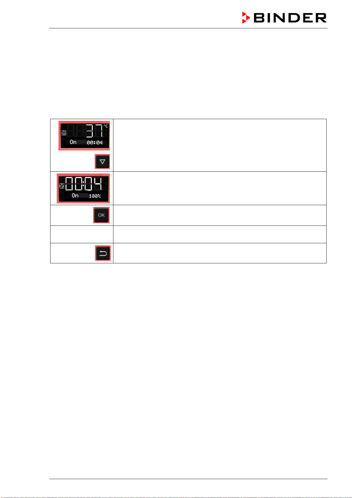
BD / BF / ED / FD / FED (E3.1) 03/2019 page 47/106
8.4.2 Changing the settings
After the timer expired, the timer function „Delayed On“ deactivates, therefore turning the function off is
not required.
As long as the timer is still running, the timer function settings can be subsequently modified in this menu.
To terminate the timer function, all time values (days, hours, minutes) must be set to zero in the according
menu.
Changing or terminating the timer function when the timer is running:
From Normal display during timer operation
2 x
with the arrow-down button to the Timer function “Delayed On” menu.
(with connected USB device: press the arrow-down button 3 times)
Timer function “Delayed On”, the timer is running.
The fan operates with the selected fan speed.
Confirm the timer function “Delayed On” with OK
see chap. 8.4.1
Modify the time values or set all time values to zero to terminate the timer
function
2x
Back to Normal display.
8.5 Temperature programming example (BF, FED)
The chamber shall heat up to a temperature of 50 °C, maintain this temperature for three hours and then
turn off.
Proceeding: Select timer function “Temperature dependent Delayed Off“ (chap. 8.3) and perform the fol-
lowing settings:
• Enter a timer run-time of 3 hours
• Enter the set point 50 °C
• Specify the fan speed after the timer expires

BD / BF / ED / FD / FED (E3.1) 03/2019 page 48/106
9. Ramp function
9.1 General information
You can program temperature ramps in order to extend heating up times. This may be necessary in some
cases to prevent temperature stress in the material during the heating up phase. Temperature ramps
should only be used if required. Using them may result in considerably slowing down the heating up
times. When the ramp function is turned off, the chamber will heat up with its maximum heating capacity.
The entry means the nominal value gradient and limits the maximum temperature increase to this value.
Due to the heat and evaporation energy assumed by the drying material, smaller temperature gradients
may also result.
A ramp proceeds from a previously entered set-point to a new, higher one. The temperature must be
equilibrated to the start set-point. Perform the setting in the following 3 steps:
1. Enter the temperature set-point as start ramp set-point and let the temperature equilibrate to this
value
2. Define the temperature increase (ramp gradient) in °C/min or in °F/min in the setting menu “Ramp
function”
You can select a gradient from „0.0“ up to „1.0“ or from „1“ up to „10“ according to the chamber type.
When setting the gradient to „0.0“ or „0“, ramp function is turned off. The chamber will then heat up
with its maximum heating capacity.
The chamber will try to heat up according to the entered gradient, i.e. with a speed of xx degree per
minute. A heating-up rate of 0.4 °C/min for the incubators BD and BF resp. 4 °C/min for the heating
and drying ovens ED, FD and FED can be regarded as a realistic maximum.
3. Enter the target ramp set-point in the “ramp function” setting menu.
As soon as the entries have been adopted, the ramp function is activated. The chamber heats up with the
entered gradient, if the set ramp target value lies above the actual temperature value.
During ramp operation the effective ramp set-point continually rises in accordance to the entered gradi-
ent from the previously entered set-point to the new one. The actual value follows this continually chang-
ing effective ramp set-point. As soon as the ramp target value is reached, this temperature is maintained
constant.
The actual temperature value, the selected gradient, and the target value are shown in Normal display.
The effective ramp set-point can be seen through the temperature set-point function.
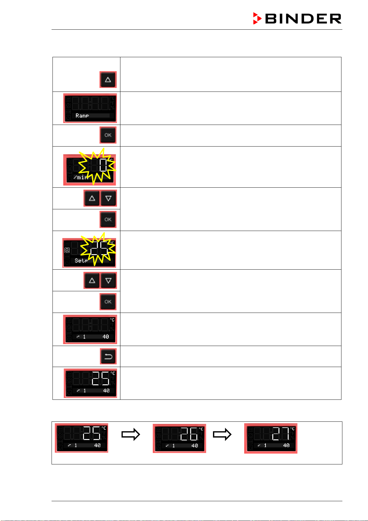
BD / BF / ED / FD / FED (E3.1) 03/2019 page 49/106
9.2 Setting and displaying the ramp function
From Normal display
without fan 3x
with fan 4x
with the arrow-up button to the Ramp function menu.
Ramp function (not programmed)
Press OK to enter the gradient in degree per minute.
The gradient flashes.
Enter the gradient (0 up to 9)
confirm with OK and go on toenter the target ramp set-point
The target ramp set-point value flashes.
Enter the target ramp set-point
and confirm with OK.
Selected ramp with gradient 1 and target ramp set-point 40 °C (example)
Back to Normal display.
Normal display showing the actual temperature, the gradient and the target
ramp set-point (example: 40 °C)
Temperature course with ramp function
Normal display
after 1
minute
Normal display
after 2
minutes
Normal display
Etc.
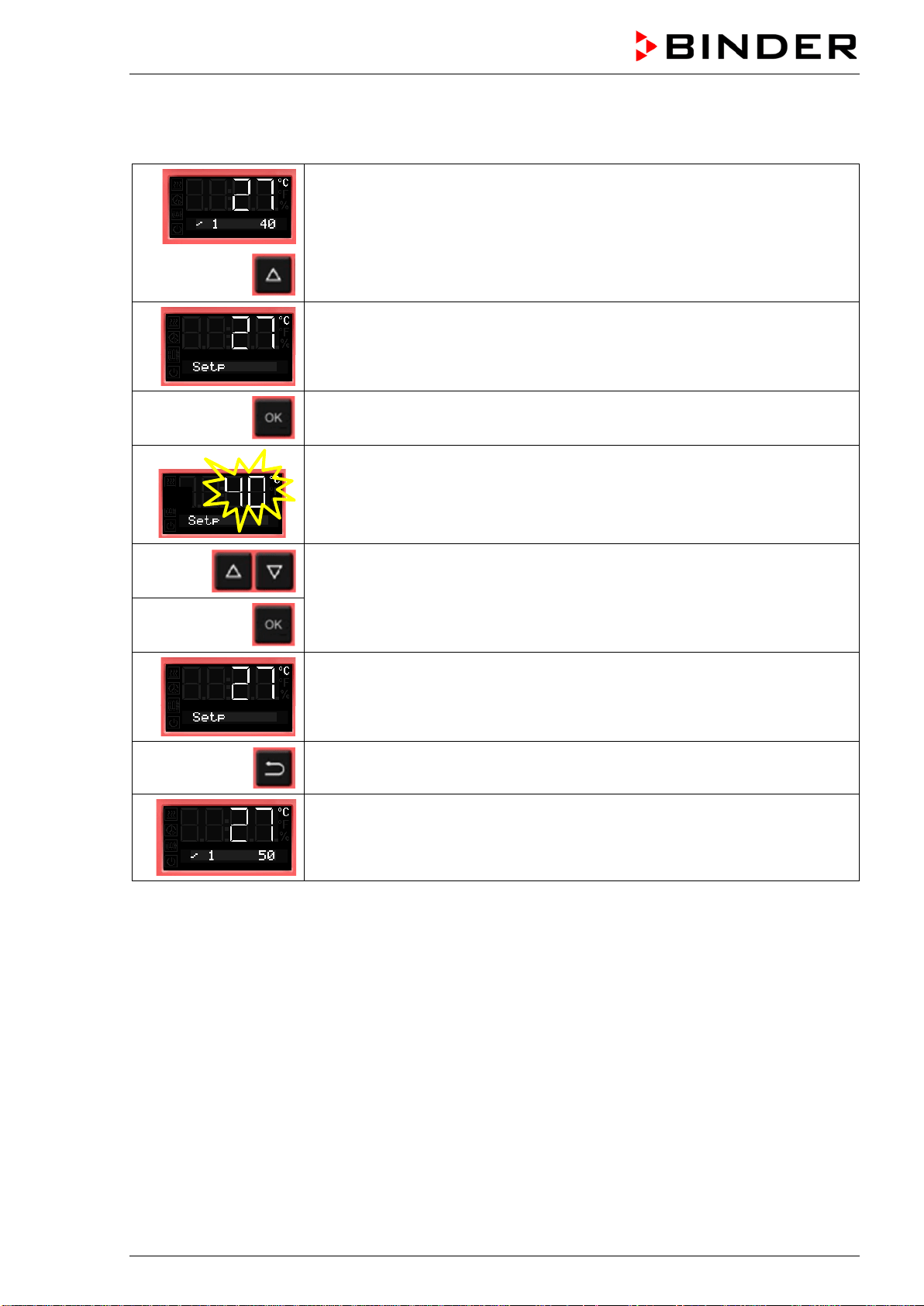
BD / BF / ED / FD / FED (E3.1) 03/2019 page 50/106
9.3 Displaying the effective ramp set-point and changing the target ramp set-
point
From Normal display showing the actual temperature (example: 27 °C), the
gradient (example: 1) and the target ramp set-point (example: 40 °C)
to the display of the effective ramp set-point
The effective ramp set-point is displayed
Press OK to set the target ramp set-point
The target ramp set-point value flashes.
Enter the target ramp set-point
and confirm with OK.
The effective ramp set-point is displayed
2x
Back to Normal display.
Normal display showing the actual temperature, the gradient and the modified
target ramp set-point (example: 50 °C)
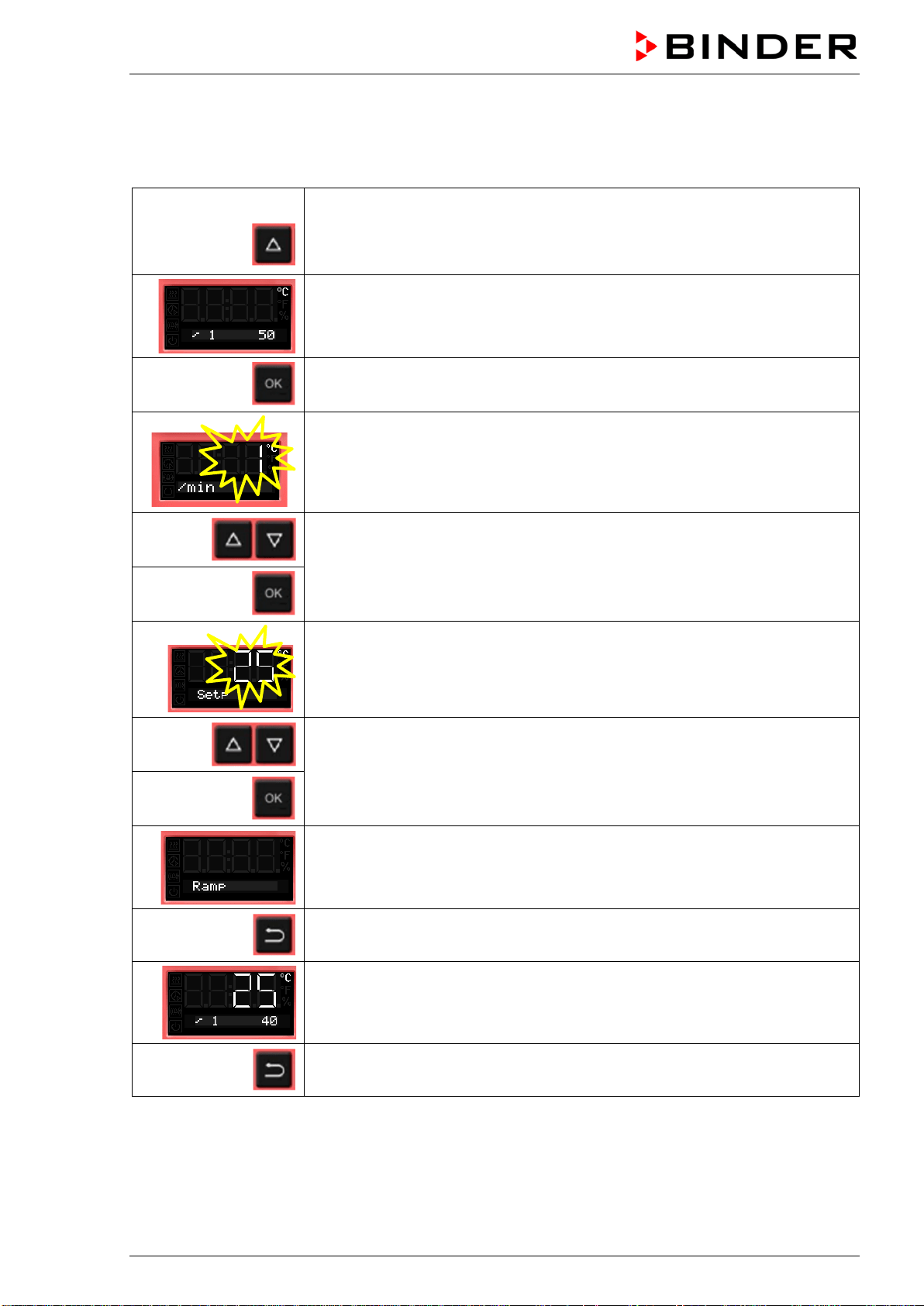
BD / BF / ED / FD / FED (E3.1) 03/2019 page 51/106
9.4 Turning off the ramp function
To turn off the ramp function, the gradient must be set to zero in the according menu. The set-point can
be entered as desired.
From Normal display
without fan 3x
with fan 4x
with the arrow-up button to the Ramp function menu
Ramp function with programmed gradient and target ramp set-point
Press OK to enter the gradient in degree per minute.
The gradient flashes.
Enter the gradient zero (turning off the ramp function)
confirm with OK and go on to the ramp target value
The target ramp set-point value flashes.
Enter the target ramp set-point
and confirm with OK.
Ramp function (not programmed)
Back to Normal display.
Normal display showing the actual temperature, the gradient and the target
ramp set-point (example: 40 °C)
2x
Back to Normal display.
Instead of turning off the ramp function (gradient = 0), you can also modify the settings of the gradient
and target ramp set-point in this menu.
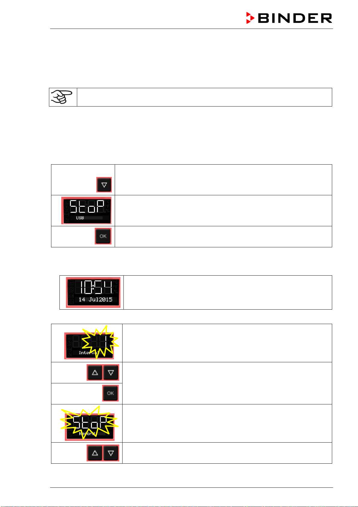
BD / BF / ED / FD / FED (E3.1) 03/2019 page 52/106
10. Data recording via USB interface
The USB interface located in the triangular instrument panel serves to read out the measured values,
which are put out in real time. Following data is recorded: Timer, actual temperature value, temperature
set-point, Object temperature sensor (chambers with option Object temperature display), Fan (chambers
with fan), air flap position, safety controller, analog output (option), heating regulation ratio.
Connect only USB sticks to the USB interface.
Data are stored directly on the USB stick. They are issued in the selected language as a spreadsheet
with the file extension “.csv” and can be further processed in the desired program.
10.1 Starting data recording
Connect the USB stick to the interface located in the triangular instrument panel.
From Normal display
with the arrow-down button to the USB menu
Current state of data recording: stopped
Confirm with OK.
Chambers without the real time clock option do not save date and time after shut-down. To make
sure that recorded data is provided with the correct date and time, with these chambers it is required
to enter date and time first :
The current date is displayed.
For setting, proceed as described in chap. 6.4.
After entry of the minute and confirmation with OK, further setting in the USB menu continues.
The data recording interval flashes.
Enter the interval in minutes
and confirm with OK.
The current state of data recording (stopped) flashes.
Change to start data recording.
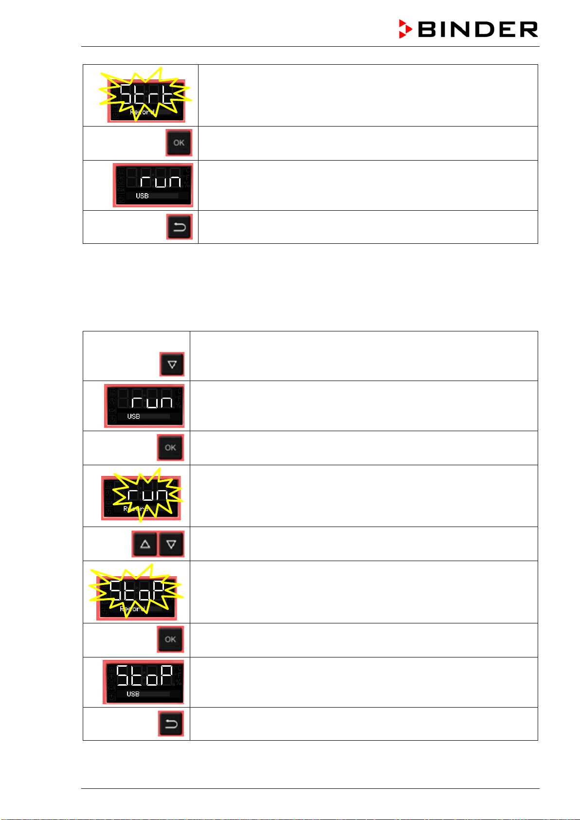
BD / BF / ED / FD / FED (E3.1) 03/2019 page 53/106
The current state of data recording (started) flashes
Confirm with OK.
Data recording is running.
Back to Normal display.
Data recording continues also during stand-by mode of the chamber. Disconnecting the power supply
interrupts data recording, which continues after the power returns. To terminate data recording, stop it via
the menu (chap. 10.2).
10.2 Terminating data recording
From Normal display
with the arrow-down button to the USB menu
Current state of data recording: running
Confirm with OK.
The current state of data recording (running) flashes
Change to stop data recording
The current state of data recording (stopped) flashes
Confirm with OK.
Data recording is stopped.
Back to Normal display.
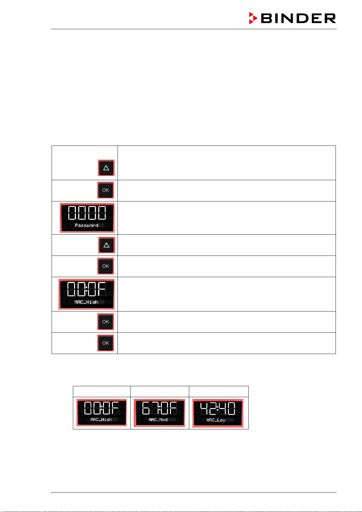
BD / BF / ED / FD / FED (E3.1) 03/2019 page 54/106
11. Network configuration for chambers with Ethernet interface
The settings of this submenu are used for networking chambers with an Ethernet interface, e.g. to con-
nect them with BINDER’s APT-COM™ 4 Multi Management Software (option, chap. 12.1).
This menu subsequently offers the following settings:
• Display of the chamber‘s MAC address (no setting)
• Switching on and off the DHCP state
• Entering the IP address
• Entering the subnet mask number
• Entering the gateway number
From Normal display
without fan 5x
with fan
6x
with the arrow-up button to the user menu
Confirm with OK.
Enter the password (factory setting: 00 00)
and confirm each entry with OK.
5 x
with the arrow-up button to the Ethernet menu.
Confirm with OK.
The first digits of the MAC address are shown.
Continue with OK. The middle digits of the MAC address are shown.
Continue with OK. The last digits of the MAC address are shown.
Displaying the chamber’s MAC address serves to identify the chamber in the Ethernet network.
Example: 00-0F-67-0F-42-40
00-0F 67-0F 42-40
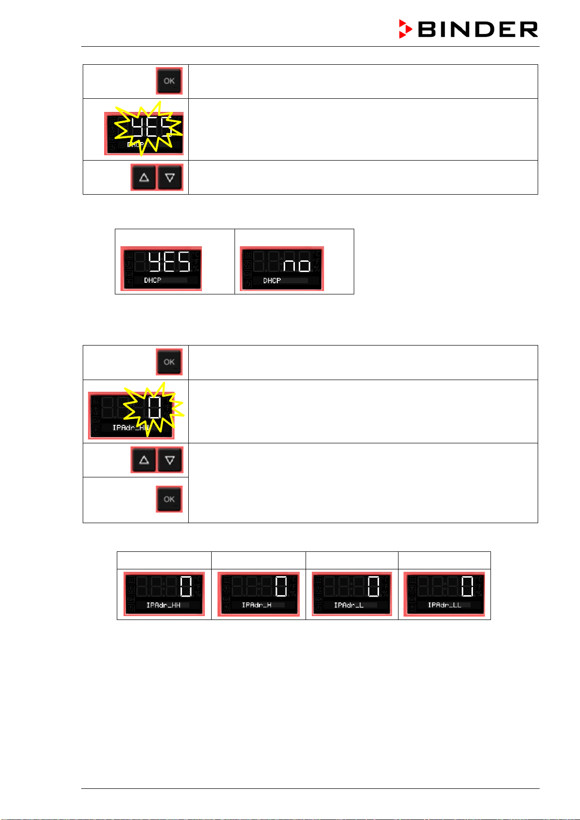
BD / BF / ED / FD / FED (E3.1) 03/2019 page 55/106
Continue with OK to switching on and off the DHCP state
The current DHCP state is displayed (on). The setting flashes.
Select the setting with the arrow buttons.
There are the following options:
DHCP switched on:
DHCP switched off:
To configure the network settings, the DHCP state must be switched off. Otherwise, the DHCP-
server would assign the network configuration..
Confirm with OK and go on to enter the IP address.
The first digits of the current IP address are shown.
The setting flashes.
Enter the desired values with the arrow buttons
and confirm with OK.
The next digits of the IP address are shown.
Enter the desired values accordingly.
Example value: 0.0.0.0
0 0 0 0
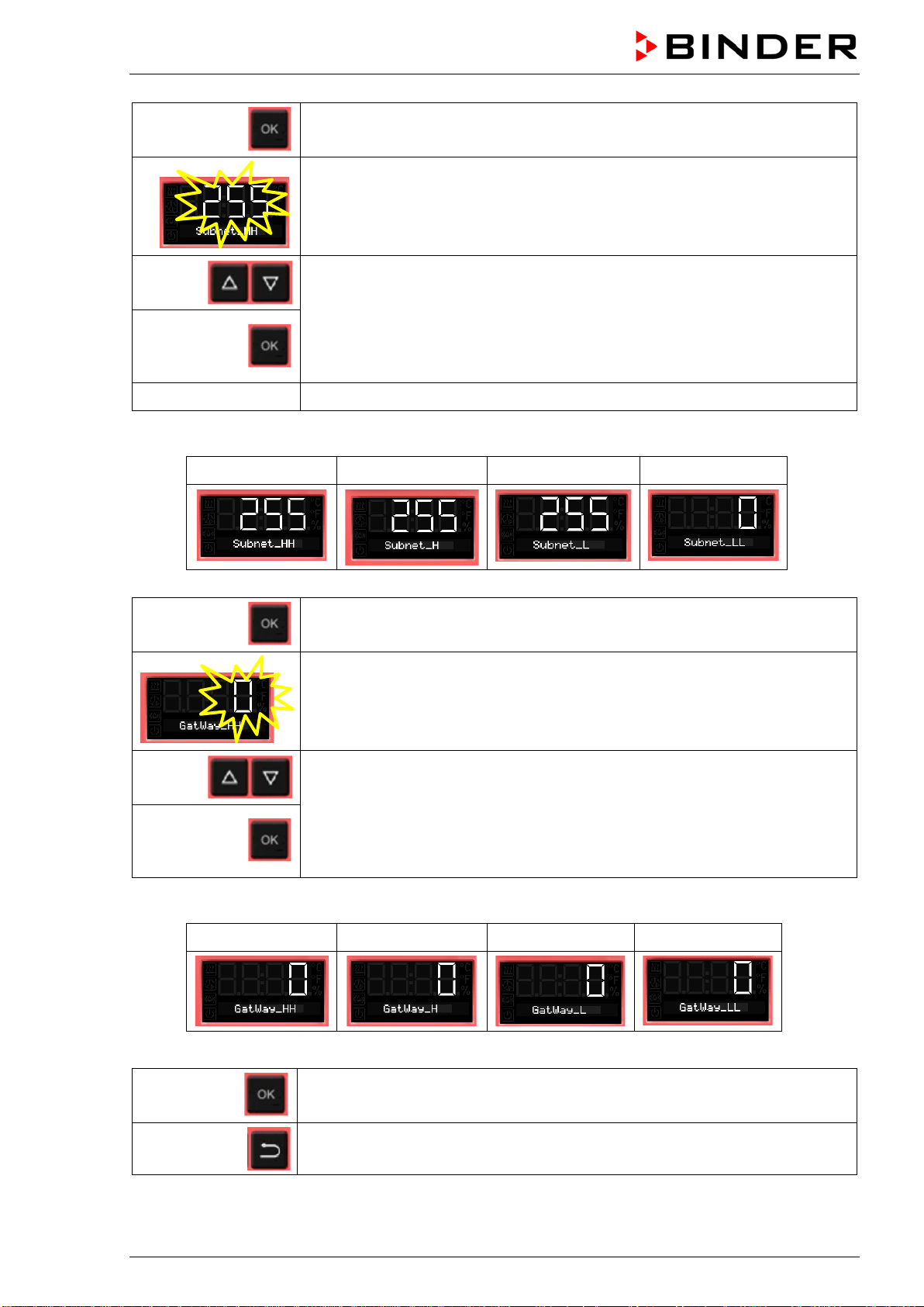
BD / BF / ED / FD / FED (E3.1) 03/2019 page 56/106
Confirm with OK and go on to enter the subnet mask.
The first digits of the current subnet mask are shown.
The setting flashes.
Enter the desired values with the arrow buttons
and confirm with OK.
The next digits of the subnet mask are shown.
Enter the desired values accordingly.
Example value: 255.255.255.0
255 255 255 0
Confirm with OK and go on to enter the gateway.
The first digits of the current gateway are shown.
The setting flashes.
Enter the desired values with the arrow buttons
and confirm with OK.
The next digits of the gateway are shown.
Enter the desired values accordingly.
Example value: 0.0.0.0
0 0 0 0
Confirm with OK.
2x
Back to Normal display.
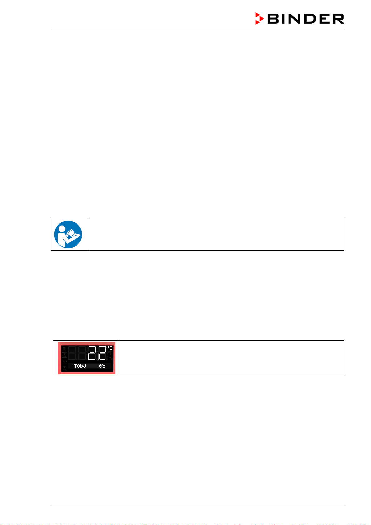
BD / BF / ED / FD / FED (E3.1) 03/2019 page 57/106
12. Options
12.1 APT-COM™ 4 Multi Management Software (option)
The chamber is regularly (FED) or optionally equipped with an Ethernet interface on the chamber rear
that can connect the BINDER APT-COM™ 4 Multi Management Software. The actual temperature value
is given at adjustable intervals. Programming can be performed graphically via PC. Up to 100 chambers
can be cross-linked. The MAC Address is indicated in the Ethernet menu (chap. 11). For further infor-
mation, please refer to the APT-COM™ 4 operating manual.
To establish a connection via the chamber’s Ethernet interface, the chamber must be turned off.
12.2 Data logger kits (option)
BINDER Data Logger Kits offer an independent long-term measuring system for temperature. They are
equipped with a keyboard and a large LCD display, alarm functions and a real-time function. Measure-
ment data are recorded in the Data Logger and can be read out after the measurement via the RS232
interface of the Data Logger. It offers a programmable measuring interval and permits storing up to 64000
measuring values. Reading out is done with the Data Logger evaluation software. You can give out a
combined alarm and status protocol directly to a serial printer.
For BD/BF: Data Logger Kit T 220: Temperature range -90 °C / -130 °F up to +220 °C / 428 °F
For ED/FD/FED: Data Logger Kit T 350: Temperature range 0 °C / 32 °F up to +350 °C / 662 °F
For detailed information on installation and operation of the BINDER Data Logger, please
refer to the mounting instructions Art. No. 7001-0204 and to the original user manual of the
manufacturer, supplied with the data logger.
12.3 Object temperature display with additional Pt100 temperature sensor (op-
tion)
With this option an additional flexible temperature sensor Pt100 measures the chamber temperature or
the temperature of the charging material which is shown on the controller. The sensor-top protective tube
of the flexible Pt100 can be immersed into liquid substances.
The object temperature display enables the determination of the actual temperature of the charging mate-
rial during the whole process. The object temperature is displayed in the controller in Normal Display.
Chamber with option object temperature display:
Actual temperature value and actual object temperature value
Technical data of thePt100 sensor:
• Three-wire technique
• Class B (DIN EN 60751)
• Temperature range up to 320 °C / 608 °F
• Stainless steel protective tube 45 mm length, material no. 1.4501
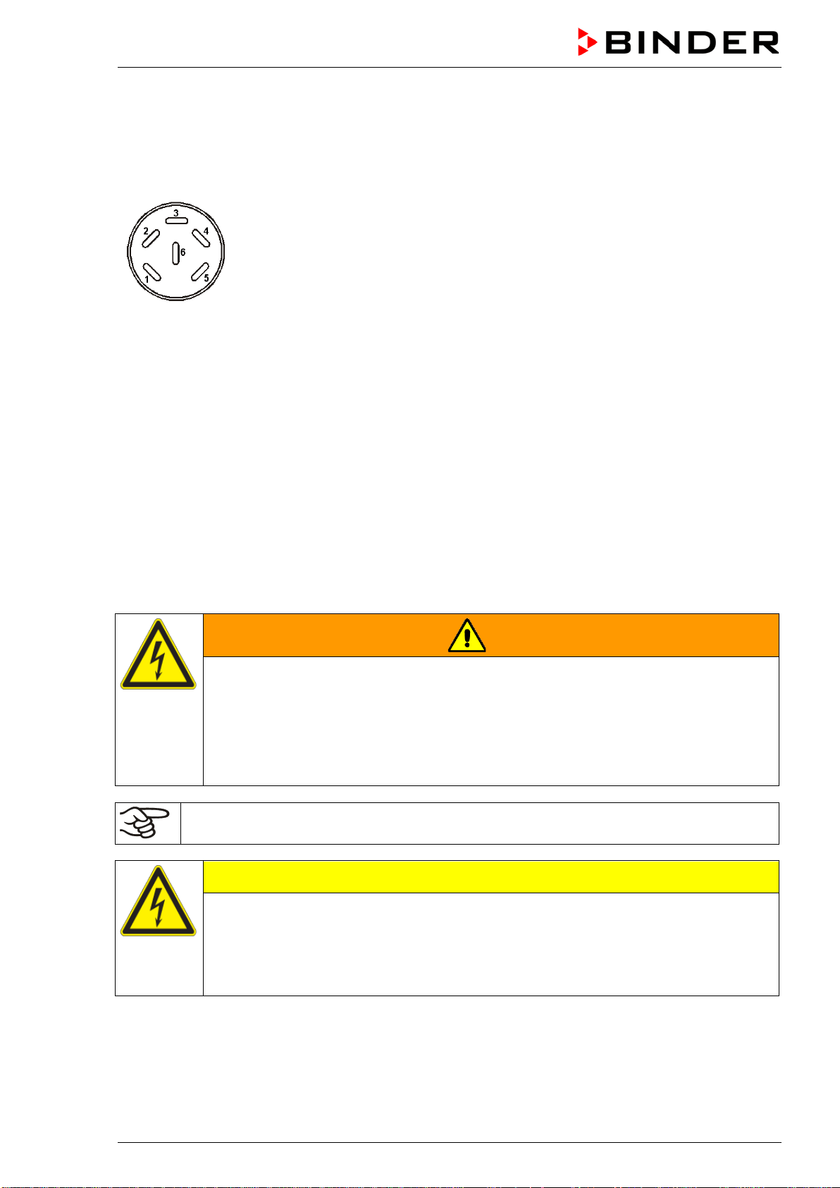
BD / BF / ED / FD / FED (E3.1) 03/2019 page 58/106
12.4 Analog output for temperature (option)
With this option the chamber is equipped with an analog output 4-20 mA for temperature. This output
permits transmitting data to external data registration systems or devices.
The connection is carried out as a DIN socket at the rear of the chamber as follows:
ANALOG OUTPUT 4-20 mA DC
PIN 1: Temperature –
PIN 2: Temperature +
Temperature range:
BD, BF: 0 °C / 32 °F to +100 °C / 212 °F
ED, FD, FED: 0 °C / 32 °F to +300 °C / 572 °F
A suitable DIN plug is enclosed.
Figure 11: Pin allocation of DIN socket for option analog outputs
12.5 Water protected disconnectable internal socket (option BD, BF)
You can turn on or off the disconnectable water protected internal socket (CA3GD) for line voltage inside
the chamber by the switch in the triangular instrument panel, independent of the incubator operating or
not. Thus, devices operated inside the incubator can be started or stopped without any need to open the
chamber doors.
The internal socket provides a protective conductor, therefore it is possible to connect appliances with
protection class I.
The internal socket is splash proof.
IP system of protection 67 230 V 1N ~ 50-60 Hz. Charge max. 500 W
Maximum permitted operating temperature with this option: 90 °C / 194 °F.
WARNING
Exceeding of the permitted maximum temperature.
Electrical hazard.
Danger of death.
Damage to the internal socket.
∅ Do NOT exceed the temperature set-point of 90 °C / 194 °F.
Set the safety controller class 3.1 to 90 °C / 194 °F.
Heat emission of electrical devices connected inside the chamber may modify the temperature
range.
CAUTION
Risk of short circuit.
Damage to the chamber.
Use the delivered plug only (IP protection type 66). Plug-in the plug and turn it to se-
cure.
If the socket is not used, close the lift-up lid and turn it for securing.
BD / BF / ED / FD / FED (E3.1) 03/2019 page 59/106
Controller shutdown by the standby button has no effect on the internal socket.
WARNING
Internal socket switched on even though controller is shut down.
Electrical hazard.
Turn off the internal socket separately, when not in use, by the switch in the triangular
instrument panel
12.6 HEPA fresh air filter (option for FD, FED)
With this option, the introduced fresh air is cleaned by means of a high efficiency submicron particulate air
filter type HEPA class H 14 (acc. to DIN EN 1822:2009). Replace the filter insert, if necessary, by remov-
ing the metal cover of the filter at the left side of the chamber (Art. No. 6014-0003).
12.7 Mostly gas-tight version (option for BF, FD, FED)
With this option the chamber is additionally sealed, so the loss when introducing gases is decreased. The
chamber is not completely gas-tight, so it is impossible to establish overpressure. The sealing diminishes
the release of vapors via the housing that may be set free from the charging material when heated. Carry-
ing-off via the regular evacuation duct, e.g. into a waste air installation, is likely to further reduce emis-
sions.
The chamber is not completely gas-tight. Gases from inside the chamber can escape into the
surrounding atmosphere.
Observe the occupational exposure limit OEL for the released substance set by the national
authorities (formerly maximum permitted workplace concentration). Respect the relevant
regulations.
Any harmful gas that might escape has to be led out via good room ventilation or a suitable
exhaust system. Place the chamber, if necessary, below a gas vent.
The air flap does not close the exhaust duct completely. The delivered plug serves to avoid emerging of
vapors or loss of introduced inert gas, if any, via the exhaust duct. Due to special demands of heat re-
sistance, use the delivered plug only.
CAUTION
Use of inappropriate plug.
Danger of inflammation.
To close the exhaust duct use the delivered plug only.
For drying purpose, please remove the plug in order to permit dissipation of the generated vapor, which
would lead to condensation in the inner chamber.
12.8 Inert gas connection with mostly gas-tight version (option for BF, FD, FED)
With this option the chamber is additionally sealed, so the loss when introducing inert gases is decreased.
For details on the mostly gas-tight version please refer to chap. 12.7.
The chamber is equipped with two ports for inert gas (nitrogen or noble gases).
The ports are located on the top panel in the middle and on the chamber rear at the bottom right.
Each of these ports can be used as inlet or outlet, depending on the nature of the inert gas:
• lighter gas (nitrogen, helium): lower port as inlet
• heavy gas (e.g. argon): upper port as inlet
This distinction is important when operating with a reduced fan speed.
BD / BF / ED / FD / FED (E3.1) 03/2019 page 60/106
Connection
Observe the legal requirements and relevant standards and regulations for the safe handling of gas cylin-
ders and inert gases.
General information for safe handling of gas cylinders:
• Store and use gas cylinders only in well ventilated areas.
• Open the gas cylinder valve slowly to avoid pressure surges
• Secure gas cylinders during storage and use against falling (chaining).
• Transport gas cylinders with a cylinder cart, do not carry, roll, or throw them
• Always close the valve even with apparently empty cylinders; screw on the cap when not in
use. Return gas cylinders with the valve closed
• Do not open gas cylinders by force. Mark them when damaged
• Observe relevant regulations for dealing with gas cylinders.
Connect a flexible gas tube to the gas hose connection adapter (diameter 10mm), which is used for gas
inlet, and secure it with hose clamps (hose and hose clamps are not enclosed). There is a constant gas
flow after establishing the connection.
After connecting the gas cylinder, check all gas connections for leaks (e.g. with leak spray or
diluted soap solution).
Use a pressure reducer and make sure to avoid any excessive outlet pressure when connecting the gas
hose to the chamber.
The chamber is not entirely gas-tight. Inert gases from inside the chamber can escape into the
surrounding atmosphere.
Inert gases in high concentrations is hazardous to health. They are colorless and almost odorless and
therefore practically imperceptible. Inhalation of inert gases can cause drowsiness up to respiratory ar-
rest. When the O
2
content of the air decreases below 18%, there is risk of death from lack of oxygen. Any
gas that might escape has to be led out via good room ventilation or a suitable exhaust system.
WARNING
High concentration of inert gas.
Risk of death by suffocation.
∅ Do NOT set up chambers in non-ventilated recesses.
Ensure technical ventilation measures.
Respect the relevant regulations for handling these gases.
Inert gases, which are heavier than air, may accumulate in low-lying areas of the installation
site.
The “Mostly gas-tight version” reduces the loss of gas.
Setting (sample values):
If you want to flush the chamber with an air exchange rate of 1 per hour, set the flow rate on the
pressure reducer according to the interior volume.
Chamber with 56 l internal volume: The flow rate corresponding to 56 l / h is 0.9 l / min.
Chamber with 115 l internal volume: The flow rate corresponding to 115 l / h is 1.9 l / min.
Chamber with 260 l internal volume: The flow rate corresponding to 260 l / h is 4.3 l / min.
The air flap does not close the exhaust duct completely. The delivered plug serves to avoid loss of intro-
duced inert gas via the exhaust duct. Due to special demands of heat resistance, use the delivered plug
only.
BD / BF / ED / FD / FED (E3.1) 03/2019 page 61/106
CAUTION
Use of inappropriate plug.
Danger of inflammation.
To close the exhaust duct use the delivered plug only.
For drying purpose, please remove the plug in order to permit dissipation of the generated vapor, which
would lead to condensation in the inner chamber.
13. Maintenance, cleaning, and service
13.1 Maintenance intervals, service
DANGER
Electrical hazard.
Danger of death.
∅ The chamber must NOT become wet during operation or maintenance work.
∅ Do NOT remove the rear panel of the chamber.
Disconnect the chamber before conducting maintenance work. Disconnect the power
plug.
Ensure all maintenance work is conducted by licensed electricians or experts author-
ized by BINDER.
Ensure regular maintenance work is performed at least once a year.
The warranty becomes void if maintenance work is conducted by non-authorized personnel..
Replace the door gasket only when cold. Otherwise, the door gasket may become damaged.
We recommend taking out a maintenance agreement. Please consult BINDER Service.
BINDER telephone hotline: +49 (0) 7462 2005 555
BINDER fax hotline: +49 (0) 7462 2005 93555
BINDER e-mail hotline: service@binder-world.com
BINDER service hotline USA: +1 866 885 9794 or +1 631 224 4340 x3 (toll-free in the USA)
BINDER service hotline Asia Pacific: +852 390 705 04 or +852 390 705 03
BINDER service hotline Russia and CIS +7 495 988 15 16
BINDER Internet website http://www.binder-world.com
BINDER address BINDER GmbH, post office box 102, D-78502 Tuttlingen
International customers, please contact your local BINDER distributor.
BD / BF / ED / FD / FED (E3.1) 03/2019 page 62/106
13.2 Cleaning and decontamination
Clean the chamber after each use to avoid potential corrosion damage by ingredients of the test material.
DANGER
Electrical hazard.
Danger of death.
∅ Do NOT spill water or cleaning agents over the inner and outer surfaces.
Disconnect the chamber before cleaning. Disconnect the power plug.
Completely dry the chamber before turning it on again.
13.2.1 Cleaning
Disconnect the chamber from the power supply before cleaning. Disconnect the power plug.
The interior of the chamber must be kept clean. Thoroughly remove any residues of the charg-
ing material
Wipe the surfaces with a moistened towel. In addition, you can use the following cleaning agents:
Exterior surfaces
inner chamber
racks
door gaskets
Standard commercial cleaning detergents free from acid or halides.
Alcohol-based solutions.
We recommend using the neutral cleaning agent Art. No. 1002-0016.
Instrument panel Standard commercial cleaning detergents free from acid or halides.
We recommend using the neutral cleaning agent Art. No. 1002-0016.
Zinc coated hinge parts
rear chamber wall
Standard commercial cleaning detergents free from acid or halides.
Do NOT use a neutral cleaning agent on zinc coated surfaces.
Do not use cleaning agents that may cause a hazard due to reaction with components of the device or
the charging material. If there is doubt regarding the suitability of cleaning products, please contact
BINDER service.
We recommend using the neutral cleaning agent Art. No. 1002-0016 for a thorough cleaning.
Any corrosive damage that may arise following use of other cleaning agents is excluded from
liability by BINDER GmbH.
Any corrosive damage caused by a lack of cleaning, is excluded from liability by BINDER
GmbH.
CAUTION
Danger of corrosion.
Damage to the chamber.
∅ Do NOT use acidic or chlorine cleaning detergents.
∅ Do NOT use a neutral cleaning agent on other kind of surfaces e.g., the zinc coated
hinge parts or the rear chamber wall.
For surface protection, perform cleaning as quickly as possible.
After cleaning completely remove cleaning agents from the surfaces with a moistened towel.
Let the chamber dry.
Soapsuds may contain chlorides and must therefore NOT be used for cleaning.
BD / BF / ED / FD / FED (E3.1) 03/2019 page 63/106
With every decontamination method, always use adequate personal safety controls.
Following cleaning, leave the chamber door open or remove the access port plugs.
The neutral cleaning agent may cause health problems in contact with skin and if ingested.
Follow the operating instructions and safety hints labeled on the bottle of the neutral clean-
ing agent.
Recommended precautions: To protect the eyes use sealed protective goggles. Suitable protective
gloves with full contact: butyl or nitrile rubber, penetration time >480 minutes.
CAUTION
Contact with skin, ingestion.
Skin and eye damage due to chemical burns.
∅ Do not ingest. Keep away from food and beverages.
∅ Do NOT empty into drains.
Wear protective gloves and goggles.
Avoid skin contact.
13.2.2 Decontamination
The operator must ensure that proper decontamination is performed in case a contamination of the
chamber by hazardous substances has occurred.
Disconnect the chamber from the power supply prior to decontamination. Pull the power plug.
Do not use decontamination agents that may cause a hazard due to reaction with components of the
device or the charging material. If there is doubt regarding the suitability of cleaning products, please
contact BINDER service.
You can use the following disinfectants:
Inner chamber Standard commercial surface disinfectants free from acid or halides.
Alcohol-based solutions.
We recommend using the disinfectant spray Art. No. 1002-0022.
For chemical disinfection, we recommend using the disinfectant spray Art. No. 1002-0022.
Any corrosive damage that may arise following use of other disinfectants is excluded from
liability by BINDER GmbH.
With every decontamination method, always use adequate personal safety controls.
BD / BF / ED / FD / FED (E3.1) 03/2019 page 64/106
In case of impurity of the interior with biological or chemical hazardous material, there are three possible
procedures depending on the type of contamination and of the charging material.
1. The drying and heating ovens ED, FD and FED can be hot air sterilized at 190 °C / 374 °F for at least
30 minutes. All inflammable goods must be removed from the interior before. With the incubators BD
and BF it is possible to perform a hot-air disinfection at 100 °C / 212 °F.
2. Spray the inner chamber with an appropriate disinfectant.
Before start-up, the chamber must be absolute dry and ventilated, because explosive gases may form
during the decontamination process.
3. BD, ED: If necessary, have strongly contaminated inner chamber parts removed by an engineer for
cleaning, or have them exchanged. Sterilize the inner chamber parts in a sterilizer or autoclave. You
can also remove and sterilize the racks.
In case of eye contact, the disinfectant spray may cause eye damage due to chemical
burns. Follow the operating instructions and safety hints labeled on the bottle of the disin-
fectant spray.
Recommended precautions: To protect the eyes use sealed protective goggles.
CAUTION
Eye contact.
Eye damage due to chemical burns.
∅ Do NOT empty into drains.
Wear protective goggles.
After using the disinfectant spray, allow the chamber to dry thoroughly, and aerate it sufficient-
ly.
13.3 Sending the chamber back to BINDER GmbH
If you return a BINDER product to us for repair or any other reason, we will only accept the product upon
presentation of an authorization number (RMA number) that has previously been issued to you. An
authorization number will be issued after receiving your complaint either in writing or by telephone prior
to your sending the BINDER product back to us. The authorization number will be issued following receipt
of the information below:
• BINDER product type and serial number
• Date of purchase
• Name and address of the dealer from which you bought the BINDER product
• Exact description of the defect or fault
• Complete address, contact person and availability of that person
• Exact location of the BINDER product in your facility
• A contamination clearance certificate (chap. 19) must be faxed in advance
The authorization number must be applied to the packaging in such a way that it can be easily recognized
or be recorded clearly in the delivery documents.
For safety reasons we cannot accept a chamber delivery if it does not carry an authorization
number.
Return address:
BINDER GmbH, Abteilung Service
Gänsäcker 16, 78502 Tuttlingen, Germany
BD / BF / ED / FD / FED (E3.1) 03/2019 page 65/106
14. Disposal
14.1 Disposal of the transport packing
Packing element
Material
Disposal
Straps to fix packing on pallet
Plastic
Plastic recycling
Wooden transport box (option)
with metal screws
Non-wood (compressed match-
wood, IPPC standard)
Wood recycling
Metal
Metal recycling
Pallet (from size 115 on)
Solid wood (IPPC standard)
Wood recycling
Transport box
with metal clamps
Cardboard
Paper recycling
Metal
Metal recycling
Top cover (size 720)
Cardboard
Paper recycling
Edge protection
Styropor
®
or PE foam
Plastic recycling
Protection of doors and racks
PE foam
Plastic recycling
Bag for operating manual
PE foil
Plastic recycling
Insulating air cushion foil (packing of
optional accessories)
PE foil Plastic recycling
If recycling is not possible, all packing parts can also be disposed of with normal waste.
14.2 Decommissioning
• ED, FD, FED size 720: Turn off the chambers at the main power switch (chap. 2.3).
• Disconnect the chamber from the power supply (pull the power plug).
• With option inert gas connection (chap. 12.8): Close the inert gas supply and remove the gas
connection.
WARNING
High concentration of inert gas.
Risk of death by suffocation.
Respect the relevant regulations for handling these gases.
When decommissioning the chamber, turn off the inert gas supply.
• Temporal decommissioning: See indications for appropriate storage, chap. 3.3.
• Final decommissioning: Dispose of the chamber as described in chap. 14.3 to 14.5.
14.3 Disposal of the chamber in the Federal Republic of Germany
According to Annex I of Directive 2012/19/EU of the European Parliament and of the Council on waste
electrical and electronic equipment (WEEE), BINDER devices are classified as “monitoring and control
instruments” (category 9) only intended for professional use“. They must not be disposed of at public col-
lecting points.
The chambers bear the symbol for the marking of electrical and electronic equipment man-
ufactured / placed on the market in the EC after 13 August 2005 and be disposed of in sep-
arate collection according to Directive 2012/19/EU on waste electrical and electronic
equipment (WEEE) and German national law for electrical and electronic equipment (El-
ektro- und Elektronikgerätegesetz, ElektroG). WEEE marking: crossed-out wheeled bin with
solid bar under. A significant part of the materials must be recycled in order to protect the
environment.
BD / BF / ED / FD / FED (E3.1) 03/2019 page 66/106
At the end of the device’s service life, have the device disposed of according to the German national law
for electrical and electronic equipment (Elektro- und Elektronikgerätegesetz, ElektroG from 20 October
2015, BGBl. I p. 1739) or contact BINDER service who will organize taking back and disposal of the
chamber according to the German national law for electrical and electronic equipment (Elektro- und El-
ektronikgerätegesetz, ElektroG from 20 October 2015, BGBl. I p. 1739).
CAUTION
Violation against existing law.
∅ Do NOT dispose of BINDER devices at public collecting points.
Have the device disposed of professionally at a recycling company which is certified
according to the German national law for electrical and electronic equipment (Elektro-
und Elektronikgerätegesetz, ElektroG from 20 October 2015, BGBl. I p. 1739).
or
Instruct BINDER Service to dispose of the device. The general terms of payment and
delivery of BINDER GmbH apply, which were valid at the time of purchasing the cham-
ber.
Certified companies disassemble waste BINDER equipment in primary substances for recycling accord-
ing to Directive 2012/19/EU. In order to eliminate any health hazards to the employees of the recycling
companies, the devices must be free from toxic, infectious or radioactive substances.
Prior to handing the chamber over to a recycling company, it is the user’s responsibility that it
is free from toxic, infectious or radioactive substances.
• Prior to disposal, clean all introduced or residual toxic substances from the chamber.
• Prior to disposal, disinfect the chamber from all sources of infection. Be aware of the fact
that sources of infection may also be located outside the inner chamber.
• If you cannot safely remove all toxic substances and sources of infection from the cham-
ber, dispose of it as “special” waste according to national law.
• Fill out the contamination clearance certificate (chap. 19) and enclose it with the chamber.
WARNING
Contamination of the device with toxic, infectious or radioactive substances.
Danger of intoxication.
Danger of infection.
∅ NEVER take a chamber contaminated with toxic substances or sources of infection for
recycling according to Directive 2012/19/EU.
Prior to disposal, remove all toxic substances and sources of infection from the cham-
ber.
Dispose of a chamber from which all toxic substances or sources of infection cannot be
safely removed as special waste according to national law.
14.4 Disposal of the chamber in the member states of the EU except for the Fed-
eral Republic of Germany
According to Annex I of Directive 2012/19/EU of the European Parliament and of the Council on waste
electrical and electronic equipment (WEEE), BINDER devices are classified as “monitoring and control
instruments” (category 9) only intended for professional use“. They must not be disposed of at public col-
lecting points.
The chambers bear the symbol for the marking of electrical and electronic equipment man-
ufactured / placed on the market in the EC after 13 August 2005 and be disposed of in sep-
arate collection according to the Directive 2012/19/EU on waste electrical and electronic
equipment (WEEE). WEEE marking: crossed-out wheeled bin with solid bar under.
BD / BF / ED / FD / FED (E3.1) 03/2019 page 67/106
At the end of the device’s service life, notify the distributor who sold you the device, who will take back
and dispose of the chamber according to the Directive 2012/19/EU on waste electrical and electronic
equipment (WEEE).
CAUTION
Violation against existing law.
∅ Do NOT dispose of BINDER devices at public collecting points.
Have the device disposed of professionally at a recycling company which is certified
according to conversion of the Directive 2012/19/EU into national law.
or
Instruct the distributor who sold you the device to dispose of it. The agreements apply
that were reached with the distributor when purchasing the chamber (e.g. his general
terms of payment and delivery).
If your distributor is not able to take back and dispose of the chamber, please contact
BINDER service.
Certified companies disassemble waste BINDER equipment in primary substances for recycling accord-
ing to Directive 2012/19/EU. In order to exclude any health hazard for the employees of the recycling
companies, the devices must be free from toxic, infectious or radioactive substances.
Prior to handing the chamber over to a recycling company, it is the user’s responsibility that it
is free from toxic, infectious or radioactive substances.
• Prior to disposal, clean all introduced or residual toxic substances from the chamber.
• Prior to disposal, disinfect the chamber from all sources of infection. Be aware of the fact
that sources of infection may also be located outside the inner chamber.
• If you cannot safely remove all sources of infection and toxic substances from the cham-
ber, dispose of it as “special” waste according to national law.
• Fill out the contamination clearance certificate (chap. 19) and enclose it with the chamber.
WARNING
Contamination of the device with toxic, infectious or radioactive substances.
Danger of intoxication.
Danger of infection.
∅ NEVER take a chamber contaminated with toxic substances or sources of infection for
recycling according to Directive 2012/19/EU.
Prior to disposal, remove all toxic substances and sources of infection from the cham-
ber.
Dispose of a chamber from which all toxic substances or sources of infection cannot be
safely removed as “special” waste according to national law.
14.5 Disposal of the chamber in non-member states of the EU
CAUTION
Alteration of the environment.
For final decommissioning and disposal of the chamber, please contact BINDER Ser-
vice.
Follow the statutory regulations for appropriate, environmentally friendly disposal.
BD / BF / ED / FD / FED (E3.1) 03/2019 page 68/106
15. Troubleshooting
Fault description
Possible cause
Required measures
Temperature
Set-point temperature is not
reached after specified time.
Chamber door not properly
closed.
Completely close chamber door.
Door gasket defective.
Replace door gasket,
Controller not adjusted.
Calibrate and adjust controller.
Wrong voltage.
Check the power supply for correct
voltage (chap. 4.2).
BF, FD, FED: The fan doesn’t
turn or turns too slowly.
BF, FED: Fan speed set too
low
BF, FED: Set fan speed to 100%
Fan defective.
Contact BINDER service.
Chamber heating permanently,
set-point not held.
Controller defective.
Contact BINDER service.
Pt 100 sensor defective.
Semiconductor relay defective
Controller not adjusted.
Calibrate and adjust controller.
Chamber doesn’t heat up. Heat-
ing icon is displayed.
Heating element defective.
Contact BINDER service.
Semiconductor relay defective.
Chamber doesn’t heat up. No
heating icon in the display. Con-
troller display working.
Timer run off.
Re-program the timer or turn it off.
Semiconductor relay defective.
Contact BINDER service.
Controller defective.
Chamber without function, the
standby icon is displayed.
Chamber in standby mode.
Press down the standby button until
the display lights up.
BD, BF: Alarm message “!TProt”
is displayed
Safety device class 3.1 has
responded.
Check the settings of the tempera-
ture set-point and of the safety de-
vice class 3.1 (chap. 7.3).
ED, FD, FED: Chamber without
function. Alarm message “!TLim”
is displayed
Safety device class 2 has
turned off the chamber.
Let cool down the chamber. Check
the settings of the temperature set-
point and of the safety device class
2 (chap. 7.3). If appropriate, select
suitable limit value.
Safety device class 2 defec-
tive.
Contact BINDER service.
Chamber without any function.
No power supply.
Check connection to power supply.
Overtemperature protective
device class 1 has turned off
the chamber.
Disconnect the chamber from the
power supply for at least 10 seconds
and let it cool down. If the device
responds again, contact BINDER
service
Controller defective.
Contact BINDER service.
Deviations from the indicated
heating-up times.
Chamber fully loaded.
Load the chamber less or consider
longer heating-up times.
Controller
Message „1999” in the controller
display
Sensor rupture between sen-
sor and controller.
Contact BINDER service.
Only qualified service personnel authorized by BINDER must perform repair.
Repaired chambers must comply with the BINDER quality standards.
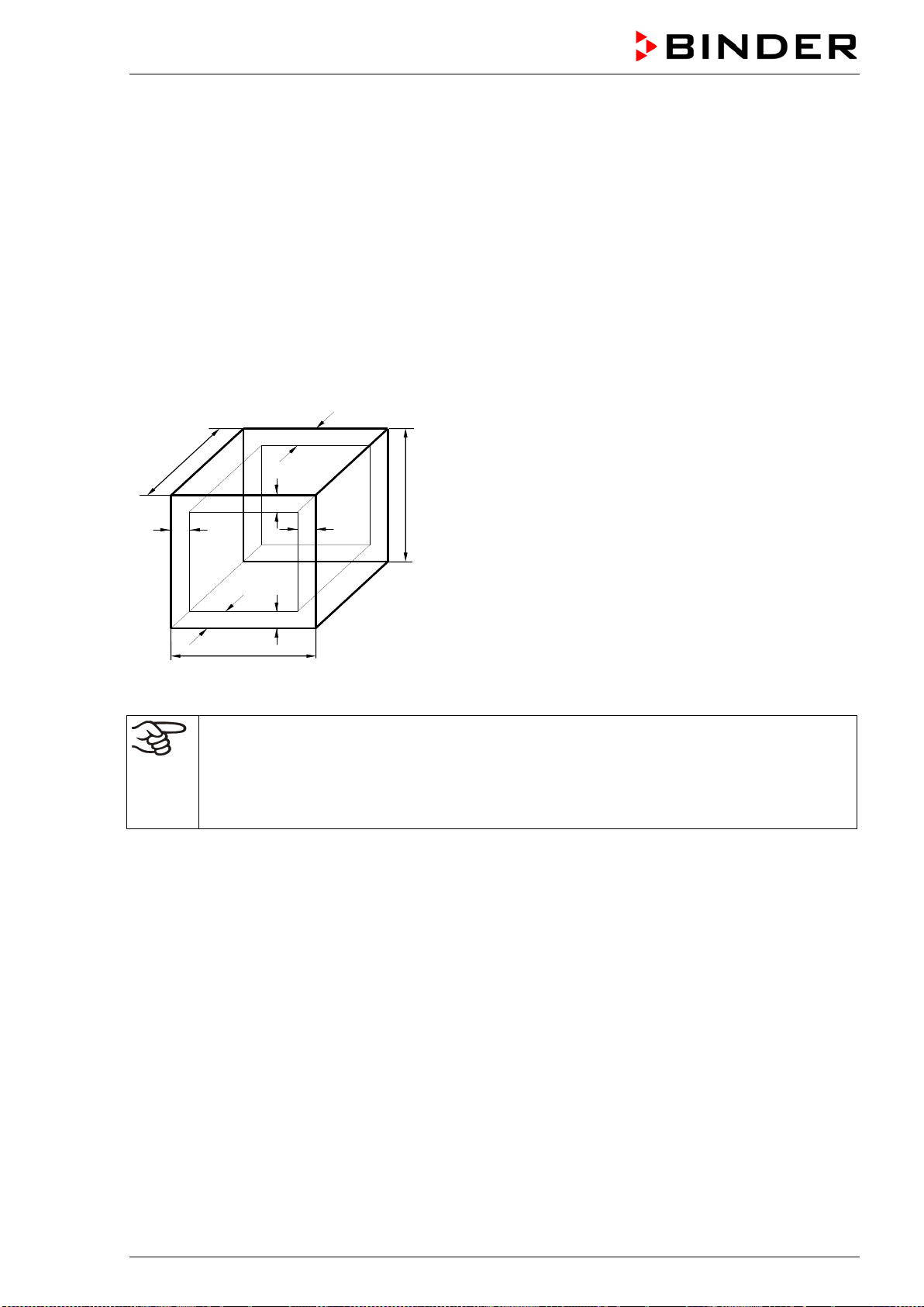
BD / BF / ED / FD / FED (E3.1) 03/2019 page 69/106
16. Technical description
16.1 Factory calibration and adjustment
This chamber was calibrated and adjusted in the factory. Calibration and adjustment were performed
using standardized test instructions, according to the QM DIN EN ISO 9001 system applied by BINDER
(certified since December 1996 by TÜV CERT). All test equipment used is subject to the administration of
measurement and test equipment that is also constituent part of the BINDER QM DIN EN ISO 9001 sys-
tems. They are controlled and calibrated to a DKD-Standard at regular intervals.
16.2 Definition of usable volume
The usable volume illustrated below is calculated as follows:
c
c
b
a
C
B
A
b
a
A, B, C = Internal dimensions (W, H, D)
a, b, c = Wall clearances
a = 0.1 x A
b = 0.1x B
c = 0.1 x C
V
USE
= (A - 2a) x (B - 2b) x (C - 2c)
Figure 12: Determination of the useable volume
The technical data refers to the defined usable volume.
Do NOT place samples outside this usable volume.
Do NOT load this volume by more than half to enable sufficient airflow inside the chamber.
Do NOT divide the usable volume into separate parts with large area samples.
Do NOT place samples too close to each other in order to permit circulation between them
and thus obtain a homogenous distribution of temperature.
16.3 Over current protection
Single-phase devices are protected by one (UL chambers) or two miniature fuses against over current,
accessible from the outside. The miniature fuses are located at the rear of the chamber above the power
cable connection. Each fuse holder is equipped with a fuse clip 5mm x 20 mm (cUL-Version 6,3x32 mm).
A fuse may be replaced only with a substitute of the same ratings. Refer to the technical data of the re-
spective device type.
Two-phase devices are equipped with a resettable miniature circuit breaker (combination element).
Three-phase devices are equipped with an internal miniature circuit breaker.
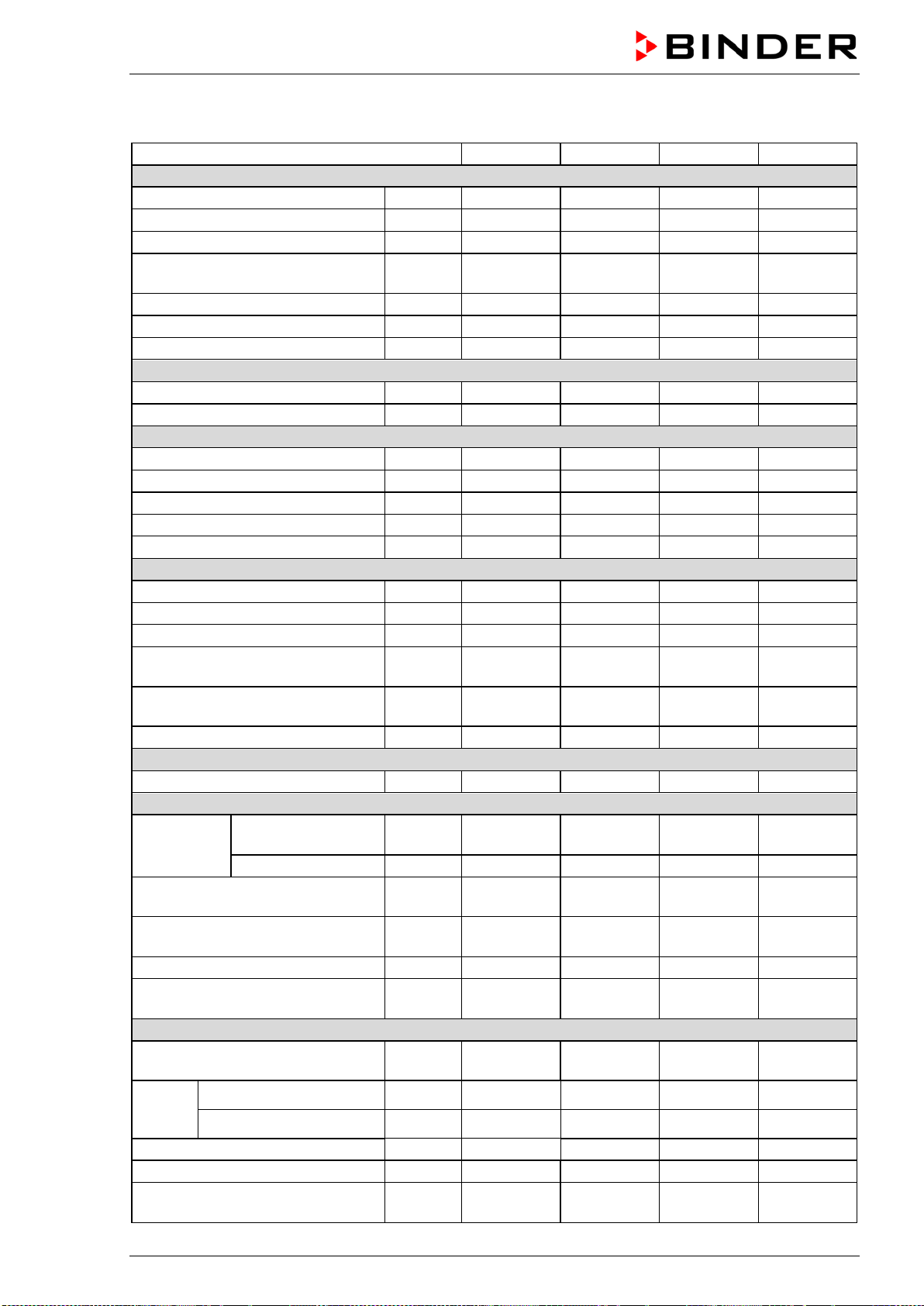
BD / BF / ED / FD / FED (E3.1) 03/2019 page 70/106
16.4 BD technical data
Chamber size
BD 56
BD 115
BD 260
BD 720
Exterior dimensions
Width, net
mm / inch
560 / 22.01
710 / 27.95
815 / 32.09
1165 / 45.87
Height, gross (incl. feet)
mm / inch
625 / 24.60
735 / 28.94
965 / 37.99
1590 / 62.60
Depth, net
mm / inch
565 / 22.24
605 / 23.82
760 / 29.92
816 / 32.13
Depth, gross (incl. door handle,
exhaust duct)
mm / inch
640 / 25.20 680 / 26.77 815 / 32.09 870 / 34.25
Wall clearance rear (minimum)
mm / inch
160 / 6.30
160 / 6.30
160 / 6.30
160 / 6.30
Wall clearance side (minimum)
mm / inch
100 / 3.94
100 / 3.94
100 / 3.94
100 / 3.94
Exhaust duct, outer diameter
mm / inch
52 / 2.05
52 / 2.05
52 / 2.05
52 / 2.05
Doors
Number of doors
1
1
1
2
Number of inner glass doors
1
1
1
2
Interior dimensions
Width
mm / inch
360 / 14.17
510 / 20.08
610 / 24.02
960 / 37.80
Height
mm / inch
420 / 16.54
530 / 20.87
760 / 29.92
1280 / 50.39
Depth
mm / inch
380 / 14.96
420 / 16.53
550 / 21.65
605 / 23.81
Interior volume
l / cu.ft.
57 / 2.01
112 / 3.96
255 / 9.01
***
Steam space volume
l / cu.ft.
63 / 2.22
127 / 4.49
279 / 9.85
***
Racks
Quantity of racks (regular)
2
2
2
2
Quantity of racks (max.)
4
5
8
16
Max. load per rack (standard rack)
Kg / lbs
30 / 66
30 / 66
40 / 88
45 / 99
Max. load per rack
(optional perforated shelf)
Kg / lbs 35 / 77 35 / 77 35 / 77 35 / 77
Max. load per rack
(optional heavy load rack)
Kg / lbs 50 / 110 70 / 154 80 / 176 70 / 154
Permitted total load
Kg / lbs
70 / 154
150 / 330
270 / 595
315 / 694
Weight
Weight (empty)
Kg / lbs
38 / 84
54 / 119
85 / 187
170 / 375
Temperature data
Temperature
range
from … degrees
above ambient
°C / °F 5 / 9 5 / 9 5 / 9 5 / 9
up to
°C / °F
100 / 212
100 / 212
100 / 212
100 / 212
Temperature fluctuation
at 37 °C / 98.6 °F
± K 0.2 0.1 0.2 0.1
Temperature uniformity (variation)
at 37 °C / 98.6 °F
± K 0.4 0.4 0.4 0.7
Heating up time to 37 °C / 98.6 °F
minutes
45
55
65
70
Recovery time after door was
opened for 30 sec at 37 °C / 98.6 °F
minutes 16 16 19 23
Electrical data (model versions BD056-230V, BD115-230V, BD260-230V, BD720-230V)
System of protection acc. to EN
60529
IP 20 20 20 20
Nominal
voltage
(+/-10%)
at 50 Hz power frequency V 230 230 230 230
at 60 Hz power frequency V 230 230 230 230
Current type
1N~
1N~
1N~
1N~
Nominal power
kW
0.30
0.35
0.85
1.65
Nominal power with option internal
socket
kW 0.80 0.85 1.35 2.15
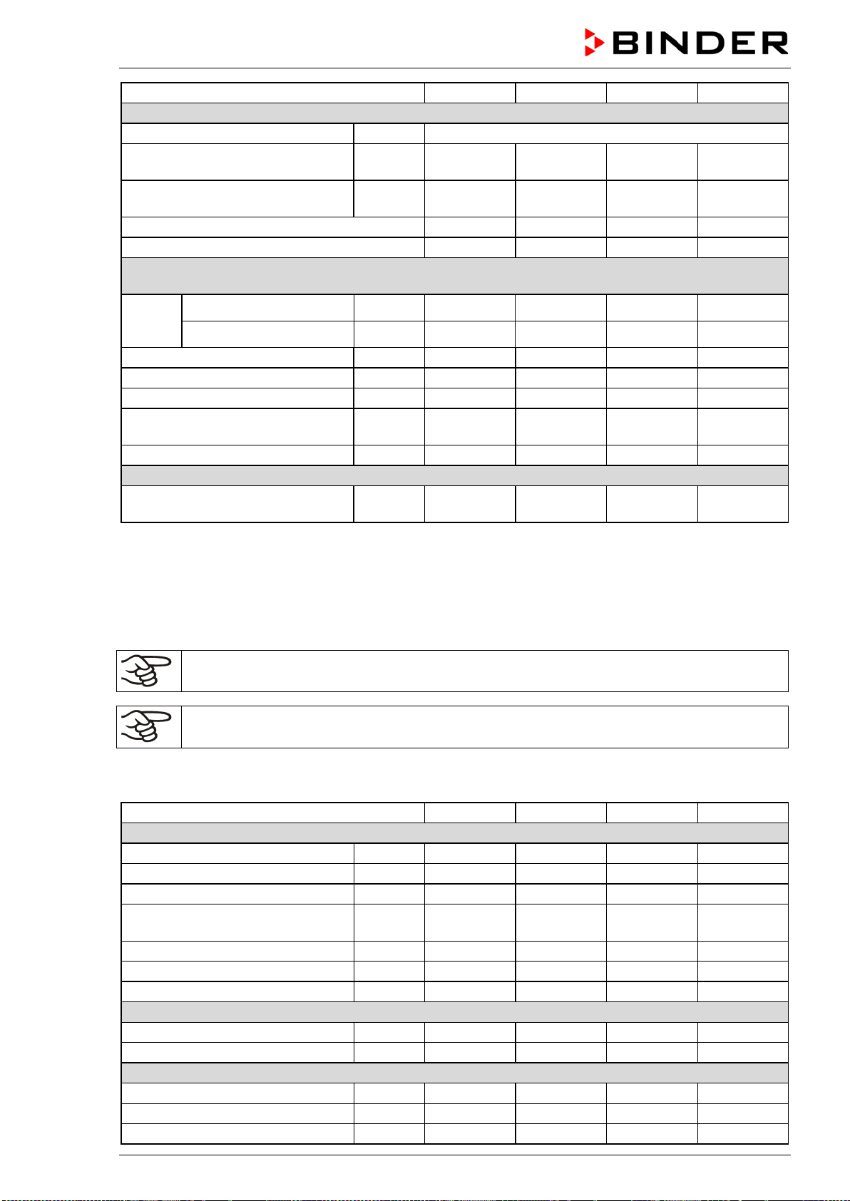
BD / BF / ED / FD / FED (E3.1) 03/2019 page 71/106
Chamber size
BD 56
BD 115
BD 260
BD 720
Electrical data (continued)
Power plug of the power cable
shock proof plug
Chamber fuse (external) 5x20 mm /
250V / time-lag (T)
A 6.3 6.3 8.0 12.5
Overtemperature protective device
class 1
°C 120 120 120 120
Installation category acc. to IEC 61010-1
II
II
II
II
Pollution degree acc. to IEC 61010-1
2
2
2
2
Different electrical data for BD-UL constructed for the USA and Canada
(model versions BD056UL-120V, BD115UL-120V, BD260UL-120V, BD720UL-240V)
Nominal
voltage
(+/-10%)
at 50 Hz power frequency V 120 120 120 240
at 60 Hz power frequency V 120 120 120 240
Current type
1N~
1N~
1N~
2~
Nominal power
kW
0,30
0,35
0,95
1,75
Power plug of the power cable
NEMA
5-15P
5-15P
5-15P
6-20P
Chamber fuse (external)
5x20 mm / 250V / time-lag (T)
A 12.5 12.5 12.5 ---
Miniature circuit breaker (internal)
A
---
---
---
16
Environment-specific data
Energy consumption at 37 °C /
98.6 °F
Wh/h 25 25 40 78
*** Data not yet determined
All technical data is specified for unloaded chambers with standard equipment at an ambient temperature
of +22 °C +/- 3°C / 71.6 °F +/- 5.4 °F and a power supply voltage fluctuation of +/-10%. Technical data is
determined in accordance to BINDER Factory Standard Part 2:2015 and DIN 12880:2007.
All indications are average values, typical for chambers produced in series. We reserve the right
to change technical specifications at any time.
If the chamber is fully loaded, the specified heating up times may vary according to the load.
With option interior socket: If electrical devices are connected and operating inside the cham-
ber, the temperature range may be modified due to heat emission.
16.5 BF technical data
Chamber size
BF 56
BF 115
BF 260
BF 720
Exterior dimensions
Width, net
mm / inch
560 / 22.01
710 / 27.95
815 / 32.09
1165 / 45.87
Height, gross (incl. feet)
mm / inch
625 / 24.60
735 / 28.94
965 / 37.99
1590 / 62.60
Depth, net
mm / inch
565 / 22.24
605 / 23.82
760 / 29.92
816 / 32.13
Depth, gross (incl. door handle and
exhaust duct)
mm / inch
640 / 25.20 680 / 26.77 815 / 32.09 870 / 34.25
Wall clearance rear (minimum)
mm / inch
160 / 6.30
160 / 6.30
160 / 6.30
160 / 6.30
Wall clearance side (minimum)
mm / inch
100 / 3.94
100 / 3.94
100 / 3.94
100 / 3.94
Exhaust duct, outer diameter
mm / inch
52 / 2.05
52 / 2.05
52 / 2.05
52 / 2.05
Doors
Number of doors
1
1
1
2
Number of inner glass doors
1
1
1
2
Interior dimensions
Width
mm / inch
400 / 15.75
550 / 21.65
650 / 25.59
1000 / 39.37
Height
mm / inch
440 / 17.32
550 / 21.65
780 / 30.71
1300 / 51.18
Depth
mm / inch
340 / 13.39
380 / 14.96
510 / 20.08
560 / 22.05
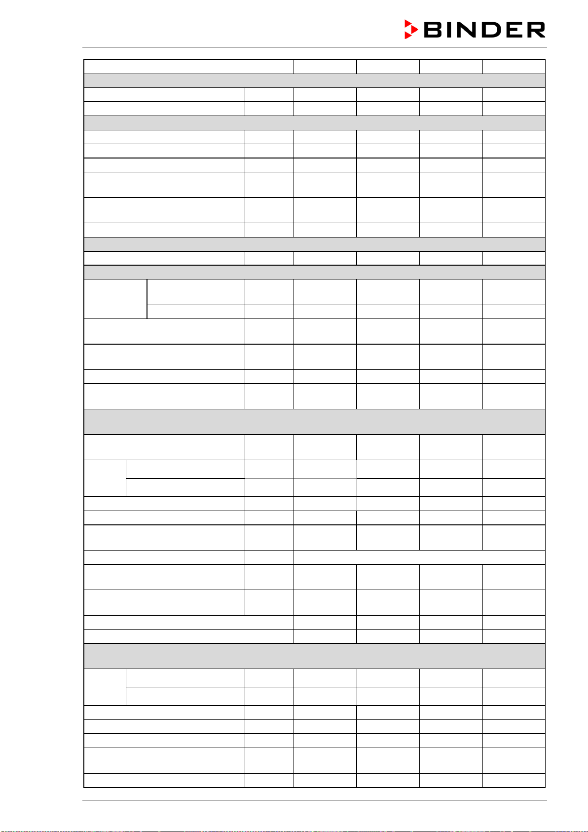
BD / BF / ED / FD / FED (E3.1) 03/2019 page 72/106
Chamber size
BF 56
BF 115
BF 260
BF 720
Interior dimensions (continued)
Interior volume
l / cu.ft.
59 / 2.08
114 / 4.03
257 / 9.08
***
Steam space volume
l / cu.ft.
66 / 2.33
127 / 4.49
279 / 9.85
***
Racks
Quantity of racks (regular)
2
2
2
2
Quantity of racks (max.)
4
5
8
16
Max. load per rack (standard rack)
Kg / lbs
30 / 66
30 / 66
40 / 88
45 / 99
Max. load per rack
(optional perforated shelf)
Kg / lbs 35 / 77 35 / 77 35 / 77 35 / 77
Max. load per rack
(optional heavy load rack)
Kg / lbs 50 / 110 70 / 154 80 / 176 70 / 154
Permitted total load
Kg / lbs
70 / 154
150 / 330
270 / 595
315 / 694
Weight
Weight (empty)
Kg / lbs
39 / 86
54 / 119
85 / 187
166 / 366
Temperature data
Temperature
range
from … degrees
above ambient
°C / °F 7 / 12.6 8 / 14.4 7 / 12.6 10 / 18
up to
°C / °F
100 / 212
100 / 212
100 / 212
100 / 212
Temperature fluctuation at 37 °C /
98.6 °F
± K 0.1 0.1 0.1 0.1
Temperature uniformity (variation)
at 37 °C / 98.6 °F
± K 0.3 0.3 0.3 0.3
Heating up time to 37 °C / 98.6 °F
minutes
8
8
8
15
Recovery time after door was
opened for 30 sec at 37 °C / 98.6 °F
minutes 3 4 4 4
Electrical data
(model versions BF056-230V, BF115-230V, BF260-230V, BF720-230V)
System of protection acc. to EN
60529
IP 20 20 20 20
Nominal
voltage
(+/-10%)
at 50 Hz power frequency
V 230 230 230 230
at 60 Hz power frequency
V 230 230 230 230
Current type
1N~
1N~
1N~
1N~
Nominal power
kW
0.40
0.40
0.90
1.75
Nominal power with option internal
socket
kW 0.90 0.95 1.45 2.25
Power plug of the power cable
shock proof plug
Chamber fuse (external)
5x20 mm / 250V / time-lag (T)
A 6.3 6.3 8.0 12.5
Overtemperature protective device
class 1
°C 120 120 120 120
Installation category acc. to IEC 61010-1
II
II
II
II
Pollution degree acc. to IEC 61010-1
2
2
2
2
Different electrical data for BF-UL constructed for the USA and Canada
(model versions BF056UL-120V, BF115UL-120V, BF260UL-120V, BF720UL-240V)
Nominal
voltage
(+/-10%)
at 50 Hz power frequency
V 120 120 120 240
at 60 Hz power frequency
V 120 120 120 240
Current type
1N~
1N~
1N~
2~
Power plug of the power cable
NEMA
5-15P
5-15P
5-15P
6-20P
Nominal power
kW
0.40
0.40
1.00
1.85
Chamber fuse (external)
5x20 mm / 250V / time-lag (T)
A 12.5 12.5 12.5 ---
Miniature circuit breaker (internal)
A
---
---
---
16
BD / BF / ED / FD / FED (E3.1) 03/2019 page 73/106
Chamber size
BF 56
BF 115
BF 260
BF 720
Environment-specific data
Noise level (mean value)
dB (A)
43
43
43
43
Energy consumption at 37 °C / 98.6
°F
Wh/h
60 60 70 130
*** Data not yet determined
All technical data is specified for unloaded chambers with standard equipment at an ambient temperature
of +22 °C +/- 3°C / 71.6 °F +/- 5.4 °F and a power supply voltage fluctuation of +/-10%. Technical data is
determined in accordance to BINDER Factory Standard Part 2:2015 and DIN 12880:2007.
All indications are average values, typical for chambers produced in series. We reserve the right
to change technical specifications at any time.
If the chamber is fully loaded, the specified heating up times may vary according to the load.
With option interior socket: If electrical devices are connected and operating inside the cham-
ber, the temperature range may be modified due to heat emission.
16.6 ED technical data
Chamber size
ED 56
ED 115
ED 260
ED 720
Exterior dimensions
Width, net
mm / inch
560 / 22.01
710 / 27.95
815 / 32.09
1165 / 45.87
Height, gross (incl. feet)
mm / inch
625 / 24.60
735 / 28.94
965 / 37.99
1590 / 62.60
Depth, net
mm / inch
565 / 22.24
605 / 23.82
760 / 29.92
816 / 32.13
Depth, gross (incl. door handle and
exhaust duct)
mm / inch
640 / 25.20 680 / 26.77 815 / 32.09 870 / 34.25
Wall clearance rear (minimum)
mm / inch
160 / 6.30
160 / 6.30
160 / 6.30
160 / 6.30
Wall clearance side (minimum)
mm / inch
100 / 3.94
100 / 3.94
100 / 3.94
100 / 3.94
Exhaust duct, outer diameter
mm / inch
52 / 2.05
52 / 2.05
52 / 2.05
52 / 2.05
Doors
Number of door(s)
1
1
1
2
Interior dimensions
Width
mm / inch
360 / 14.17
510 / 20.08
610 / 24.02
960 / 37.80
Height
mm / inch
420 / 16.54
530 / 20.87
760 / 29.92
1280 / 50.39
Depth
mm / inch
380 / 14.96
425 / 16.73
550 / 21.65
610 / 24.02
Interior volume
l / cu.ft.
57 / 2.01
114 / 4.03
255 / 9.01
***
Steam space volume
l / cu.ft.
63
127 / 4.49
273 / 9.64
***
Racks
Quantity of racks (regular)
2
2
2
2
Quantity of racks (max.)
4
5
8
16
Max. load per rack (standard rack)
Kg / lbs
30 / 66
30 / 66
44 / 88
45 / 99
Max. load per rack (optional perfo-
rated shelf)
Kg / lbs 35 / 77 35 / 77 35 / 77 35 / 77
Max. load per rack (optional heavy
load rack)
Kg / lbs 50 / 110 70 / 154 80 / 176 70 / 154
Permitted total load
Kg / lbs
70 / 154
150 / 330
270 / 595
315 / 694
Weight
Weight (empty)
Kg / lbs
39 / 86
54 / 119
85 / 187
169 / 373
BD / BF / ED / FD / FED (E3.1) 03/2019 page 74/106
Chamber size
ED 56
ED 115
ED 260
ED 720
Temperature data
Temperature
range
from … degrees
above ambient
°C / °F 5 / 9 5 / 9 5 / 9 5 / 9
up to
°C / °F
300 / 572
300 / 572
300 / 572
300 / 572
Temperature fluctuation at 150 °C /
302 °F
± K 0.5 0.4 1.0 0.8
Temperature uniformity (variation)
at 150 °C / 302 °F
± K 2.5 2.0 2.0 3,2
Heating up time to 150 °C / 302 °F
minutes
45
45
55
85
Recovery time after door was
opened for 30 sec at 150 °C /
302 °F
minutes 35 16 20 25
Electrical data
(model versions ED056-230V, ED115-230V, ED260-230V, ED720-400V)
IP system of protection acc. to EN
60529
IP 20 20 20 20
Nominal
voltage
(+/-10%)
at 50 Hz power frequency
V 230 230 230 400
at 60 Hz power frequency
V 230 230 230 400
Current type
1N~
1N~
1N~
3N~
Nominal power
kW
1.05
1.25
2.25
4.10
Power plug of the power cable
shock proof plug
Chamber fuse (external)
5x20 mm / 250V / time-lag (T)
A 6.3 6.3 12.5 ---
Miniature circuit breaker (internal)
A
---
---
---
16
Overtemperature protective device
class 1
°C 330 330 330 330
Installation category acc. to IEC 61010-1
II
II
II
II
Pollution degree acc. to IEC 61010-1
2
2
2
2
Different electrical data for ED-UL constructed for the USA and Canada
(model versions ED056UL-120V, ED115UL-120V, ED260UL-240V)
Nominal
voltage
(+/-10%)
at 50 Hz power frequency
V 120 120 240 ---
at 60 Hz power frequency
V 120 120 240 ---
Current type
1N~
1N~
2~
---
Power plug of the power cable
NEMA
5-15P
5-15P
6-20P
---
Nominal power
kW
1.15
1.35
2.45
---
Chamber fuse (external)
5x20 mm / 250V / time-lag (T)
A 12.5 12.5 --- ---
Miniature circuit breaker
(combination element, external)
A --- --- 16 ---
Environment-specific data
Energy consumption at 150 °C /
302 °F
Wh/h 180 250 370 700
*** Data not yet determined
All technical data is specified for unloaded chambers with standard equipment at an ambient temperature
of +22 °C +/- 3°C / 71.6 °F +/- 5.4 °F and a power supply voltage fluctuation of +/-10%. Technical data is
determined in accordance to BINDER Factory Standard Part 2:2015 and DIN 12880:2007.
All indications are average values, typical for chambers produced in series. We reserve the right
to change technical specifications at any time.
If the chamber is fully loaded, the specified heating up times may vary according to the load.
BD / BF / ED / FD / FED (E3.1) 03/2019 page 75/106
16.7 FD technical data
Chamber size
FD 56
FD 115
FD 260
FD 720
Exterior dimensions
Width, net
mm / inch
560 / 22.01
710 / 27.95
815 / 32.09
1165 / 45.87
Height, gross (incl. feet)
mm / inch
625 / 24.60
735 / 28.94
965 / 37.99
1590 / 62.60
Depth, net
mm / inch
565 / 22.24
605 / 23.82
760 / 29.92
816 / 32.13
Depth, gross (incl. door handle and
exhaust duct)
mm / inch
640 / 25.20 680 / 26.77 815 / 32.09 870 / 34.25
Wall clearance rear (minimum)
mm / inch
160 / 6.30
160 / 6.30
160 / 6.30
160 / 6.30
Wall clearance side (minimum)
mm / inch
100 / 3.94
100 / 3.94
100 / 3.94
100 / 3.94
Exhaust duct, outer diameter
mm / inch
52 / 2.05
52 / 2.05
52 / 2.05
52 / 2.05
Doors
Number of door(s)
1
1
1
Interior dimensions
Width
mm / inch
400 / 15.75
550 / 21.65
650 / 25.59
1000 / 39.37
Height
mm / inch
440 / 17.32
550 / 21.65
780 / 30.71
1300 / 51.18
Depth
mm / inch
345 / 13.58
385 / 15.16
510 / 20.08
570 / 22.44
Interior volume
l / cu.ft.
60 / 2.12
116 / 4.10
257 / 9.08
***
Steam space volume
l / cu.ft.
67 / 2.37
127 / 4.49
279 / 9.85
***
Racks
Quantity of racks (regular)
2
2
2
2
Quantity of racks (max.)
4
5
8
16
Max. load per rack (standard rack)
Kg / lbs
30 / 66
30 / 66
44 / 88
45 / 99
Max. load per rack (optional perfo-
rated shelf)
Kg / lbs 35 / 77 35 / 77 35 / 77 35 / 77
Max. load per rack (optional heavy
load rack)
Kg / lbs 50 / 110 70 / 154 80 / 176 70 / 154
Permitted total load
Kg / lbs
70 / 154
150 / 330
270 / 595
315 / 694
Weight
Weight (empty)
Kg / lbs
39 / 86
54 / 119
85 / 187
166 / 366
Temperature data
Temperature range
from … de-
grees above
ambient
°C / °F 10 / 18 10 / 18 10 / 18 12 / 21.6
up to
°C / °F
300 / 572
300 / 572
300 / 572
300 / 572
Temperature fluctuation at 150 °C /
302 °F
± K 0.3 0.3 0.5 0.6
Temperature uniformity (variation)
at 150 °C / 302 °F
± K 1.7 1.7 1.9 2.5
Heating up time to 150 °C / 302 °F
minutes
15
19
20
25
Recovery time after door was
opened for 30 sec at 150 °C / 302
°F
minutes 4 5 6 6
Ventilation data
Air change
at 100 °C /
212 °F
x/h
80 32 9 ***
Electrical data
(model versions FD056-230V, FD115-230V, FD260-230V, FD720-400V)
System of protection acc. to EN
60529
IP 20 20 20 20
Nominal
voltage
(+/-10%)
at 50 Hz power frequency
V 230 230 230 400
at 60 Hz power frequency
V 230 230 230 400

BD / BF / ED / FD / FED (E3.1) 03/2019 page 76/106
Chamber size
FD 56
FD 115
FD 260
FD 720
Electrical data (continued)
(model versions FD056-230V, FD115-230V, FD260-230V, FD720-400V)
Current type
1N~
1N~
1N~
3N~
Nominal power
kW
1.10
1.30
2.30
4.50
Power plug of the power cable
shock proof plug
Chamber fuse (external)
5x20 mm / 250V / time-lag (T)
A 6.3 6.3 12.5 ---
Miniature circuit breaker (internal)
A
---
---
---
16
Overtemperature protective device
class 1
°C 330 350 330 330
Installation category acc. to IEC 61010-1
II
II
II
II
Pollution degree acc. to IEC 61010-1
2
2
2
2
Different electrical data for FD-UL constructed for the USA and Canada
(model versions FD056UL-120V, FD115UL-120V, FD260UL-240V)
Nominal
voltage
(+/-10%)
at 50 Hz power frequency
V 120 120 240 ---
at 60 Hz power frequency
V 120 120 240 ---
Current type
1N~
1N~
2~
---
Nominal power
kW
1.20
1.40
2.50
---
Power plug of the power cable
NEMA
5-15P
5-15P
6-20P
---
Chamber fuse (external)
5x20 mm / 250V / time-lag (T)
A 12.5 12.5 --- ---
Miniature circuit breaker (combina-
tion element)
A --- --- 16 ---
Environment-specific data
Noise level (mean value)
dB (A)
43
43
43
43
Energy consumption at 150 °C /
302 °F
Wh/h
300 340 420 800
*** Data not yet determined
All technical data is specified for unloaded chambers with standard equipment at an ambient temperature
of +22 °C +/- 3°C / 71.6 °F +/- 5.4 °F and a power supply voltage fluctuation of +/-10%. Technical data is
determined in accordance to BINDER Factory Standard Part 2:2015 and DIN 12880:2007.
All indications are average values, typical for chambers produced in series. We reserve the right
to change technical specifications at any time.
If the chamber is fully loaded, the specified heating up times may vary according to the load.
16.8 FED technical data
Chamber size
FED 56
FED 115
FED 260
FED 720
Exterior dimensions
Width, net
mm / inch
560 / 22.01
710 / 27.95
815 / 32.09
1165 / 45.87
Height, gross (incl. feet)
mm / inch
625 / 24.60
735 / 28.94
965 / 37.99
1590 / 62.60
Depth, net
mm / inch
565 / 22.24
605 / 23.82
760 / 29.92
816 / 32.13
Depth, gross (incl. door handle and
exhaust duct)
mm / inch
640 / 25.20 680 / 26.77 815 / 32.09 870 / 34.25
Wall clearance rear (minimum)
mm / inch
160 / 6.30
160 / 6.30
160 / 6.30
160 / 6.30
Wall clearance side (minimum)
mm / inch
100 / 3.94
100 / 3.94
100 / 3.94
100 / 3.94
Exhaust duct, outer diameter
mm / inch
52 / 2.05
52 / 2.05
52 / 2.05
52 / 2.05
Doors
Number of door(s)
1
1
1
BD / BF / ED / FD / FED (E3.1) 03/2019 page 77/106
Chamber size
FED 56
FED 115
FED 260
FED 720
Interior dimensions
Width
mm / inch
400 / 15.75
550 / 21.65
650 / 25.59
1000 / 39.37
Height
mm / inch
440 / 17.32
550 / 21.65
780 / 30.71
1300 / 51.18
Depth
mm / inch
345 / 13.58
385 / 15.16
510 / 20.08
570 / 22.44
Interior volume
l / cu.ft.
60 / 2.12
116 / 4.10
257 / 9.08
***
Steam space volume
l / cu.ft.
67 / 2.37
127 / 4.49
279 / 9.85
***
Racks
Quantity of racks (regular)
2
2
2
2
Quantity of racks (max.)
4
5
8
16
Max. load per rack (standard rack)
Kg / lbs
30 / 66
30 / 66
44 / 88
45 / 99
Max. load per rack (optional perfo-
rated shelf)
Kg / lbs 35 / 77 35 / 77 35 / 77 35 / 77
Max. load per rack (optional heavy
load rack)
Kg / lbs 50 / 110 70 / 154 80 / 176 70 / 154
Permitted total load
Kg / lbs
70 / 154
150 / 330
270 / 595
315 / 694
Weight
Weight (empty)
Kg / lbs
39 / 86
54 / 119
85 / 187
162 / 357
Temperature data
Temperature range
from … de-
grees above
ambient
°C / °F 10 / 18 10 / 18 10 / 18 12 / 21.6
up to
°C / °F
300 / 572
300 / 572
300 / 572
300 / 572
Temperature fluctuation at 150 °C /
302 °F
± K 0.3 0.3 0.5 0.6
Temperature uniformity (variation)
at 150 °C / 302 °F
± K 1.4 1.2 1.6 2.0
Heating up time to 150 °C / 302 °F
minutes
15
19
20
25
Recovery time after door was
opened for 30 sec at 150 °C / 302
°F
minutes 4 5 6 6
Ventilation data
Air change
at 100 °C /
212 °F
x/h
80 32 9 ***
Electrical data
(model versions FED056-230V, FED115-230V, FED260-230V, FED720-400V)
System of protection acc. to EN
60529
IP 20 20 20 20
Nominal voltage
(+/-10%)
at 50 Hz power
frequency
V 230 230 230 400
at 60 Hz power
frequency
V 230 230 230 400
Current type
1N~
1N~
1N~
3N~
Nominal power
kW
1.10
1.30
2.30
4.50
Power plug of the power cable
shock proof plug
Chamber fuse (external)
5x20 mm / 250V / time-lag (T)
A 6.3 6.3 12.5 ---
Miniature circuit breaker (internal)
A
---
---
---
16
Overtemperature protective device
class 1
°C 330 350 330 330
Installation category acc. to IEC 61010-1
II
II
II
II
Pollution degree acc. to IEC 61010-1
2
2
2
2
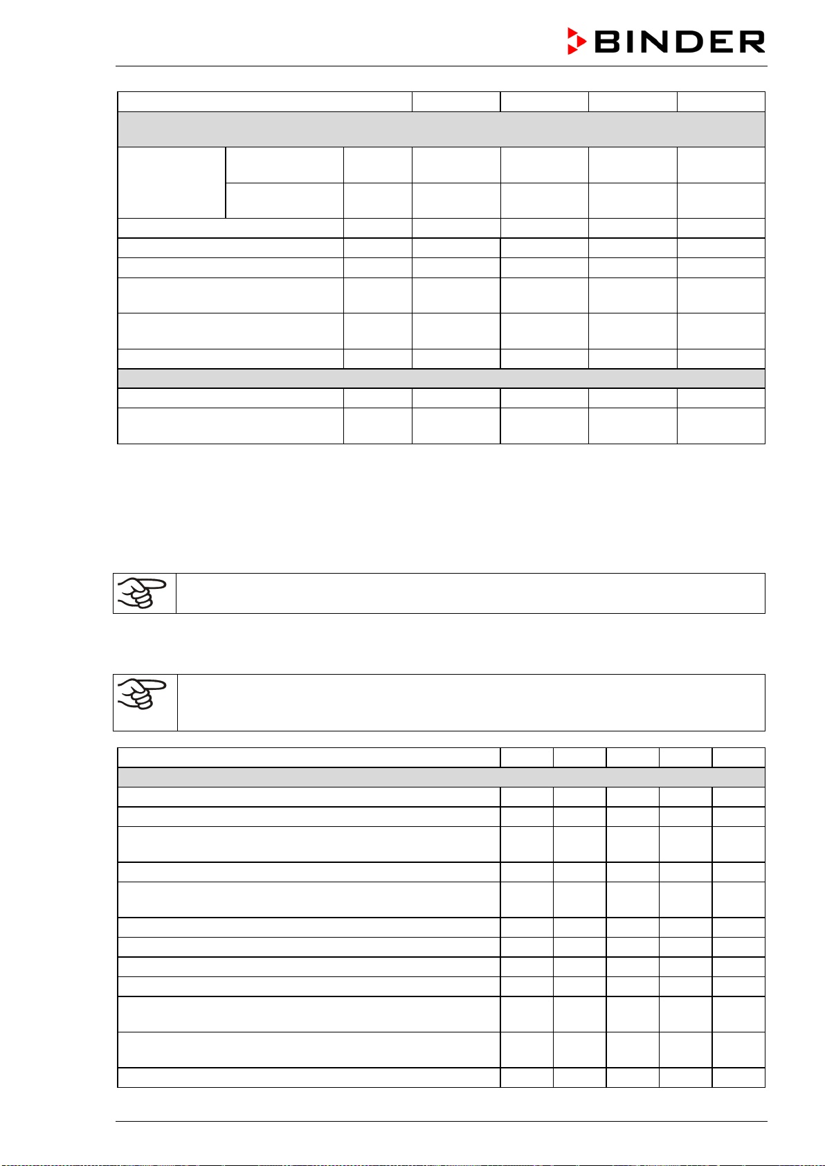
BD / BF / ED / FD / FED (E3.1) 03/2019 page 78/106
Chamber size
FED 56
FED 115
FED 260
FED 720
Different electrical data for FED-UL constructed for the USA and Canada
(model versions FED056UL-120V, FED115UL-120V, FED260UL-240V, FED720UL-208V)
Nominal voltage
(+/-10%)
at 50 Hz power
frequency
V 120 120 240 208
at 60 Hz power
frequency
V 120 120 240 208
Current type
1N~
1N~
2~
3N~
Nominal power
kW
1.20
1.40
2.50
4.50
Power plug of the power cable
NEMA
5-15P
5-15P
6-20P
L21-20P
Chamber fuse (external)
5x20 mm / 250V / time-lag (T)
A 12.5 12.5 --- ---
Miniature circuit breaker (combina-
tion element, external)
A --- --- 16 ---
Miniature circuit breaker (internal)
A
---
---
---
16
Environment-specific data
Noise level (mean value)
dB (A)
43
43
43
43
Energy consumption at 150 °C /
302 °F
Wh/h
300 340 420 800
*** Data not yet determined
All technical data is specified for unloaded chambers with standard equipment at an ambient temperature
of +22 °C +/- 3°C / 71.6 °F +/- 5.4 °F and a power supply voltage fluctuation of +/-10%. Technical data is
determined in accordance to BINDER Factory Standard Part 2:2015 and DIN 12880:2007.
All indications are average values, typical for chambers produced in series. We reserve the right
to change technical specifications at any time.
If the chamber is fully loaded, the specified heating up times may vary according to the load.
16.9 Equipment and options (extract)
To operate the chamber, use only original BINDER accessories or accessories / components
from third-party suppliers authorized by BINDER. The user is responsible for any risk arising
from using unauthorized accessories.
BD
BF
ED
FD
FED
Standard equipment
Microprocessor temperature controller
√
√
√
√
√
One timer function: Delayed Off
√
√
√
Three timer functions: Delayed On, Delayed Off and
Temperature dependent Delayed Off
√ √
Adjustable ramp function
√
√
√
√
√
Temperature safety controller class 3.1 acc. to DIN
12880:2007
√ √
Temperature safety controller class 2 acc. to DIN 12880:2007
√
√
√
Inner glass door
√
√
USB interface to read out the measured values
√
√
√
√
√
Communication interface Ethernet
√
Exhaust duct, internal diameter 50 mm / 1.97 inches, with
adjustable ventilation slide
√ √ √ √ √
Adjustable air change by means of rear exhaust duct (50
mm)
√ √ √ √ √
2 racks, chrome-plated
√
√
√
√
√
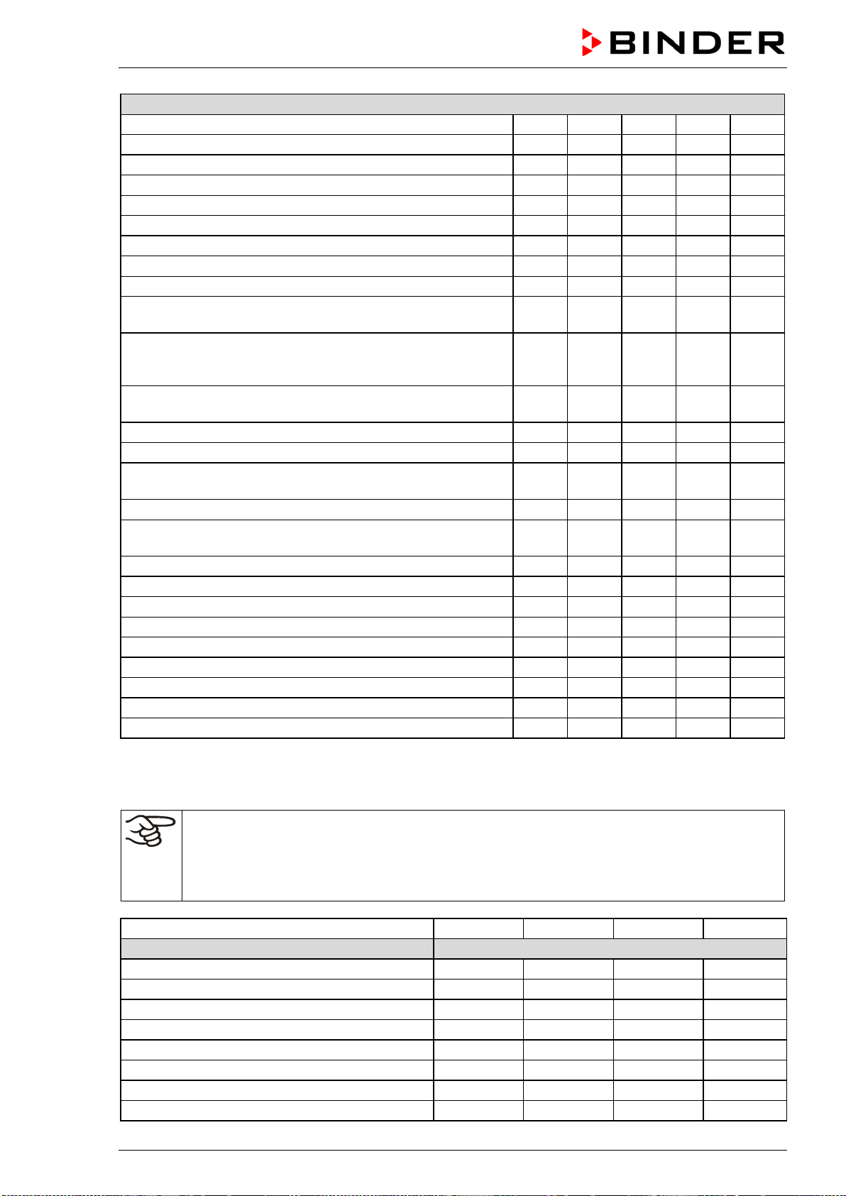
BD / BF / ED / FD / FED (E3.1) 03/2019 page 79/106
Options / accessories
Rack, chrome-plated or stainless steel
√
√
√
√
√
Perforated rack, stainless steel
√
√
√
√
√
Heavy load rack, stainless steel
√
√
√
√
√
Access ports with various diameters, with silicone plug
√
√
√
√
√
Door with window
√
√
√
Interior lightning
√
√
√
√
√
Communication interface Ethernet
√
√
√
√
Battery backed real-time clock
√
√
√
√
√
Rubber pads for safe stacking (4 pieces)
√
√
√
√
√
Object temperature display with additional Pt100 temperature
sensor
√ √ √ √ √
Disconnectable water protected internal socket (CA3GD) for
line voltage inside the chamber, IP type of protection 67, 230
V 1N ~ 50-60 Hz. Max. load 500 W
√ √
Analog output 4-20 mA for temperature with 6 pole DIN sock-
et, DIN plug included
√ √ √ √ √
HEPA Fresh air filter, class H 14 (DIN EN 1822:2009)
√
√
Mostly gas-tight version
√
√
√
Inert gas connection (gas inlet and outlet), with mostly gas-
tight version
√ √ √
Disconnectable audible over-temperature alarm
√
√
√
√
√
FKM door gasket (temperature resistant up to 200 °C / 392 °F
max.)
√ √ √
Data Logger Kit T 220
√
√
Data Logger Kit T 350
√
√
√
Measurement of air change rate acc. to ASTM D5374
√
√
√
Factory calibration certificate
√
√
√
√
√
Extension to factory calibration certificate (additional values)
√
√
√
√
√
Measuring protocol acc. to DIN 12880:2007
√
√
√
√
√
Qualification folder
√
√
√
√
√
Neutral cleaning agent (liquid concentrate)
√
√
√
√
√
Stable table on wheels with castors and locking brakes
√
√
√
√
√
16.10 Accessories and spare parts (extract)
BINDER GmbH is responsible for the safety features of the chamber only, provided skilled
electricians or qualified personnel authorized by BINDER perform all maintenance and repair,
and if components relating to chamber safety are replaced in the event of failure with original
spare parts. The user is responsible for any risks arising from using unauthorized accesso-
ries/components.
Chamber size
56
115
260
720
Description
Art. No.
Rack, chrome-plated BD, ED
6004-0174
6004-0175
6004-0177
6004-0179
Rack, chrome-plated BF, FD, FED
6004-0166
6004-0167
6004-0169
6004-0171
Rack, stainless steel BD, ED
6004-0158
6004-0159
6004-0161
6004-0163
Rack, stainless steel BF, FD, FED
6004-0150
6004-0151
6004-0153
6004-0155
Perforated rack, stainless steel BD, ED
6004-0190
6004-0191
6004-0193
6004-0195
Perforated rack, stainless steel BF, FD, FED
6004-0182
6004-0183
6004-0185
6004-0187
Rack, heavy load, stainless steel BD, ED
6004-0201
6004-0202
6004-0203
6004-0205
Rack, heavy load, stainless steel BF, FD, FED
6004-0198
6004-0199
6004-0200
6004-0204

BD / BF / ED / FD / FED (E3.1) 03/2019 page 80/106
Chamber size
56
115
260
720
Description
Art. No.
Door gasket, silicone
6005-0254
6005-0255
6005-0258
6005-0260
Door gasket made of FKM (temperature resistant
up to 200 °C / 392 °F max.)
6005-0265 6005-0266 6005-0268 6005-270
Stable table on wheels with castors and locking
brakes
9051-0005 9051-0005 9051-0006 ---
Chamber fuse 5x20mm 250V 6,3 A time lag (T)
5006-0092
5006-0092
---
---
Chamber fuse 5x20mm 250V 8,0 A time lag (T)
---
---
5006-0093
---
Chamber fuse 5x20mm 250V 12,5 A time lag (T)
5006-0096
5006-0096 5006-0096
---
External
housing with HEPA Fresh air filter, class
H 14 (DIN EN 1822:2009)
8012-1050 8012-1051 8012-1052 ***
Description
Art. No.
HEPA fresh air filter (replacement) class H 14 (DIN EN 1822:2009)
6014-0003
Rubber pads for safe stacking (4 pieces)
8012-0001
Data Logger kit T 220
8012-0715
Data Logger kit T 350
8012-0714
Data Logger software
8012-0821
Neutral cleaning agent, 1 kg
1002-0016
Chamber type
BD
BF
ED
FD
FED
Validation service
Art.-No.
Qualification folder IQ-OQ
8012-0870
8012-0871
8012-0761
8012-0792
8012-0855
Qualification folder IQ-OQ-PQ
8012-0958
8012-0959
8012-0942
8012-0943
8012-0944
Execution of IQ-OQ
DL400100
DL400100
DL400100
DL400100
DL400100
Execution of IQ-OQ-PQ
DL440500
DL440500
DL440500
DL440500
DL440500
Chamber type
BD
BF
ED
FD
FED
Calibration service
Art.-No.
Calibration of temperature including certifi-
cate (1 measuring point)
DL300101
DL300101
DL300101 DL300101
DL300101
Spatial temperature measurement including
certificate (9 measuring points)
DL300109
DL300109
DL300109 DL300109
DL300109
Spatial temperature measurement including
certificate (18 measuring points)
DL300118
DL300118
DL300118 DL300118
DL300118
Spatial temperature measurement including
certificate (27 measuring points)
DL300127
DL300127
DL300127 DL300127
DL300127
Measurement of air ventilation acc. to ASTM
D 5374, including certificate
-- -- DL330000 DL330000
DL330000
For information on components not listed here, please contact BINDER Service.
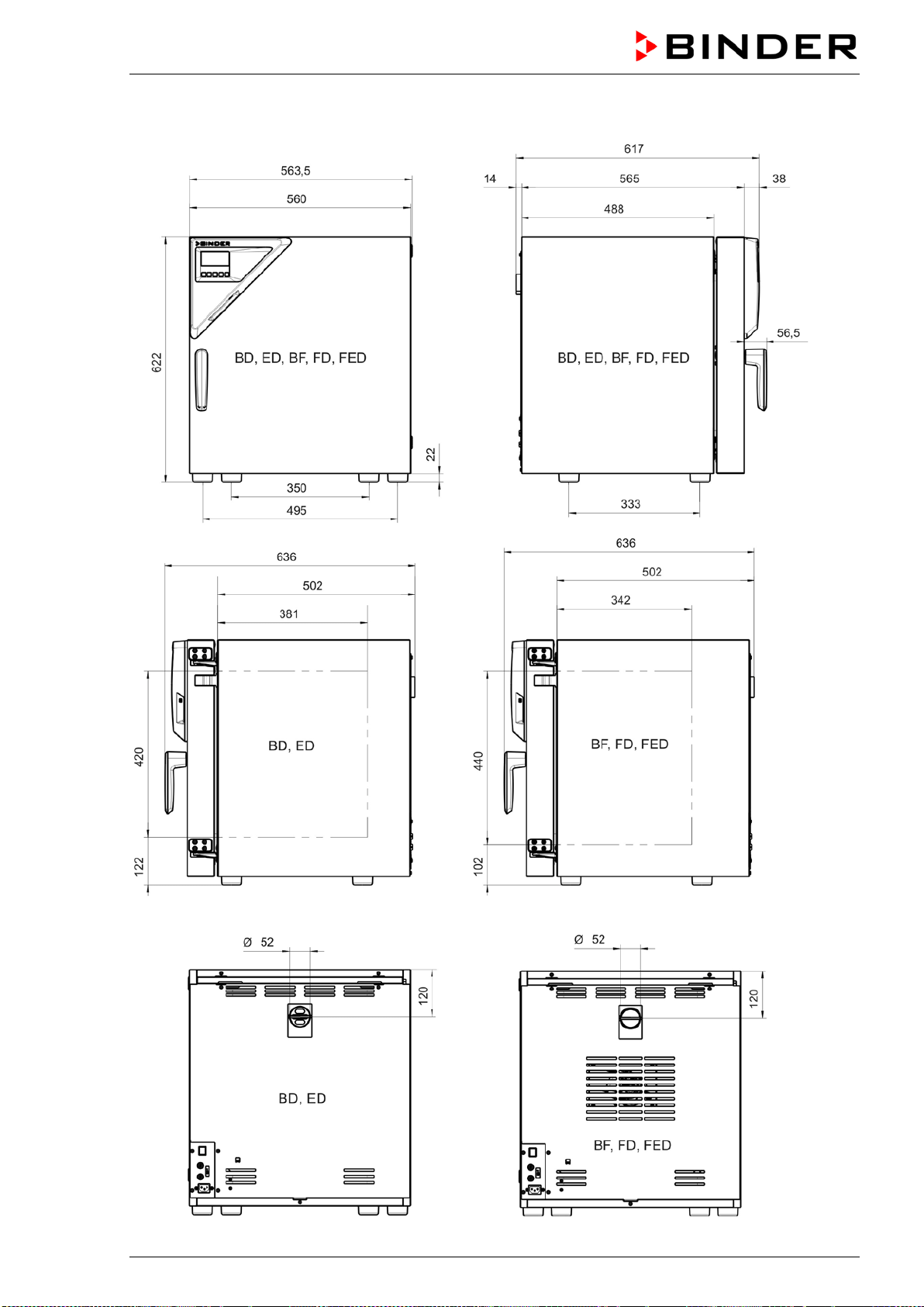
BD / BF / ED / FD / FED (E3.1) 03/2019 page 81/106
16.11 Dimensions size 56
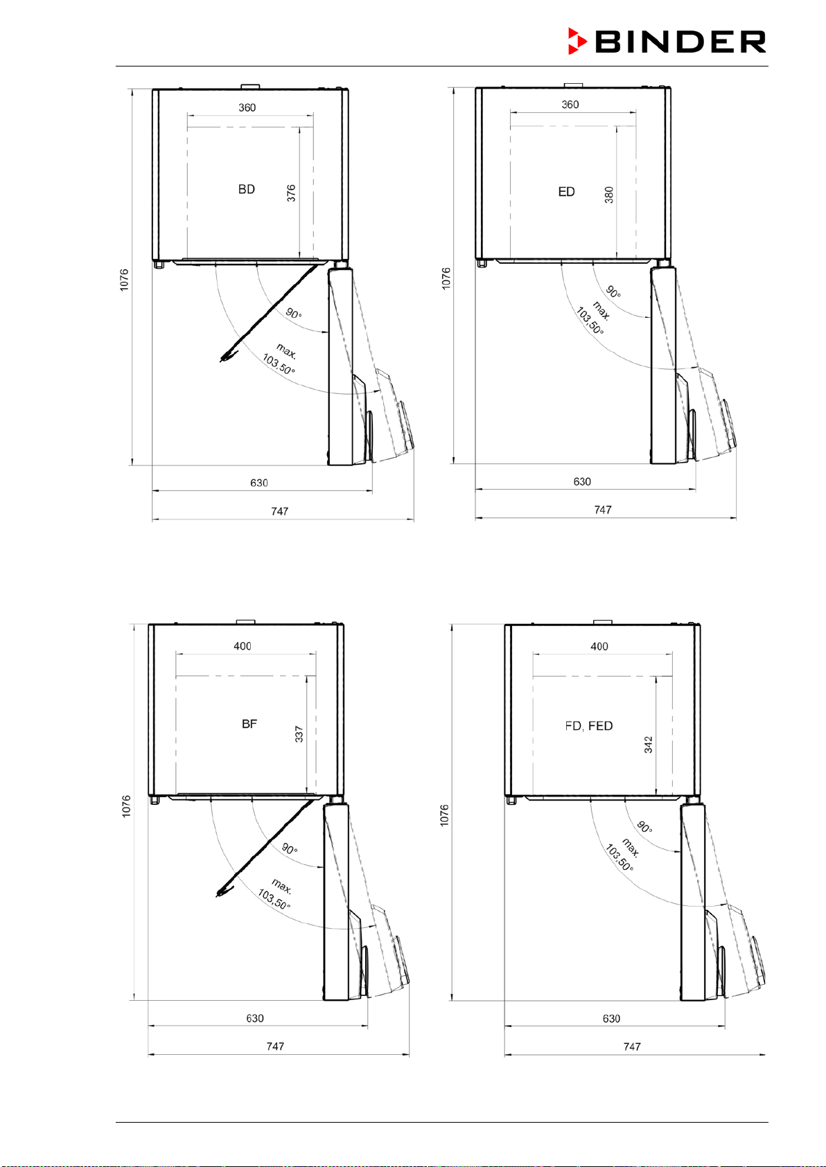
BD / BF / ED / FD / FED (E3.1) 03/2019 page 82/106
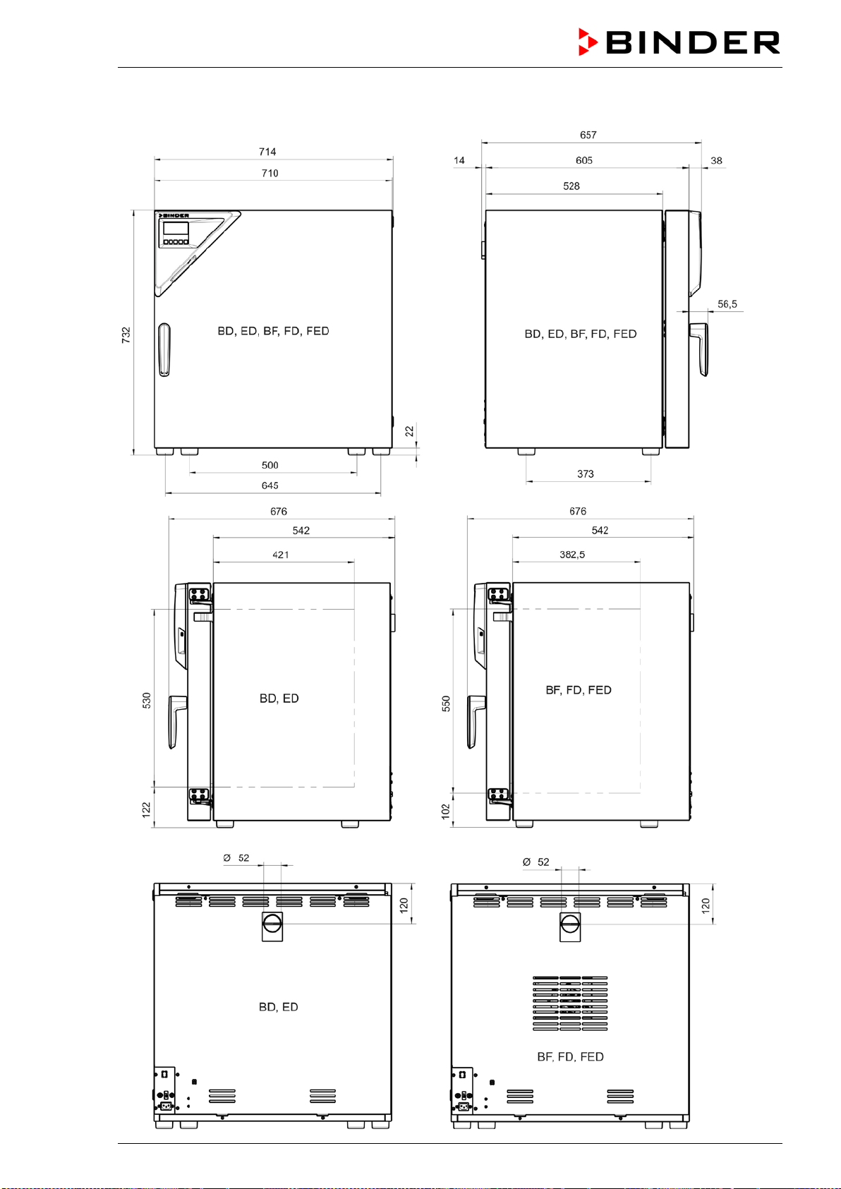
BD / BF / ED / FD / FED (E3.1) 03/2019 page 83/106
16.12 Dimensions size 115
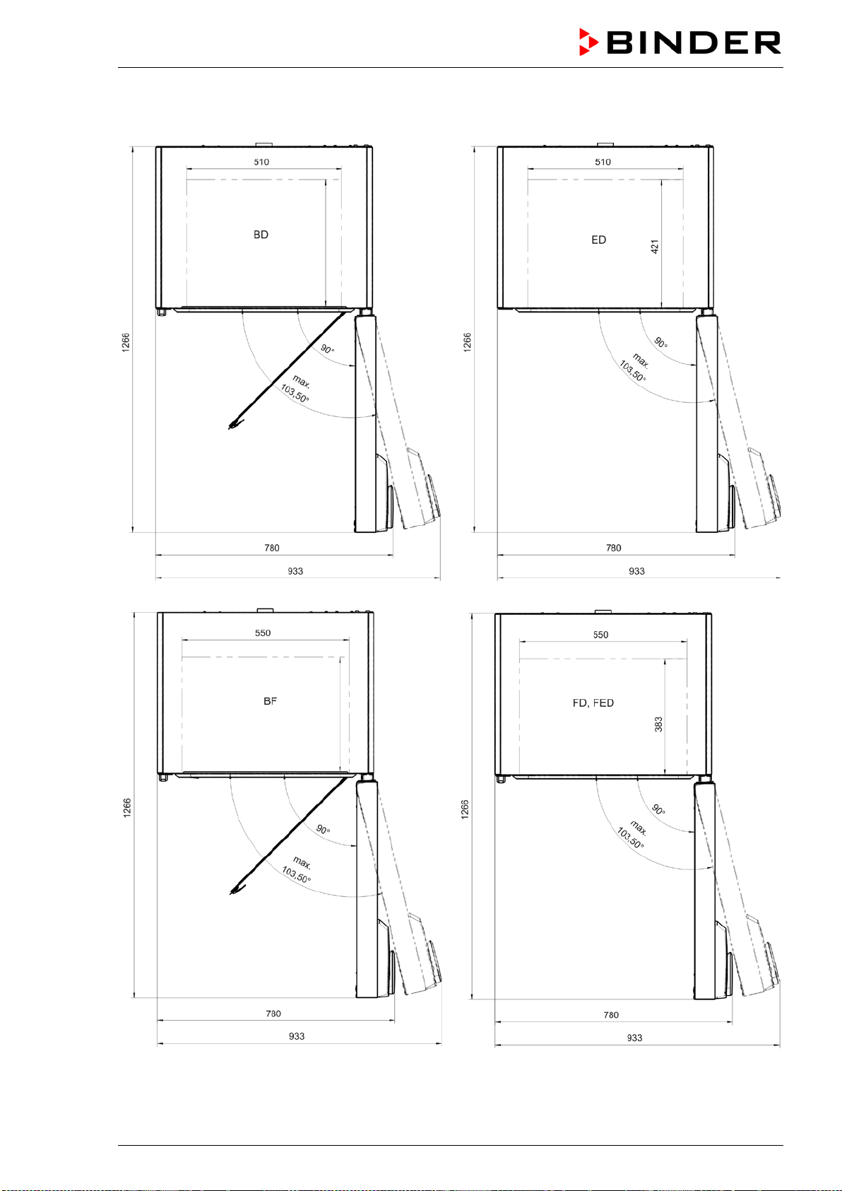
BD / BF / ED / FD / FED (E3.1) 03/2019 page 84/106
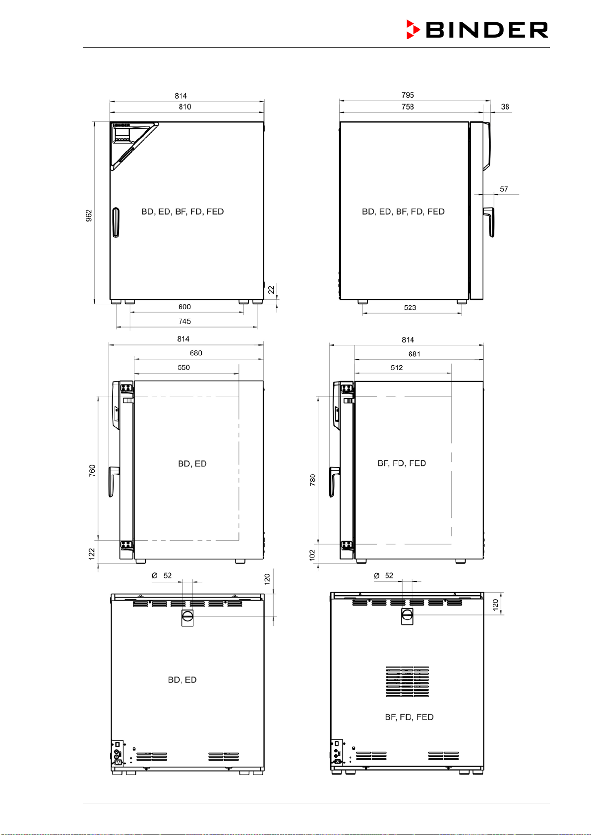
BD / BF / ED / FD / FED (E3.1) 03/2019 page 85/106
16.13 Dimensions size 260
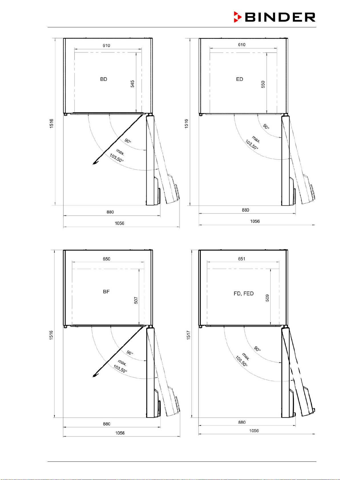
BD / BF / ED / FD / FED (E3.1) 03/2019 page 86/106
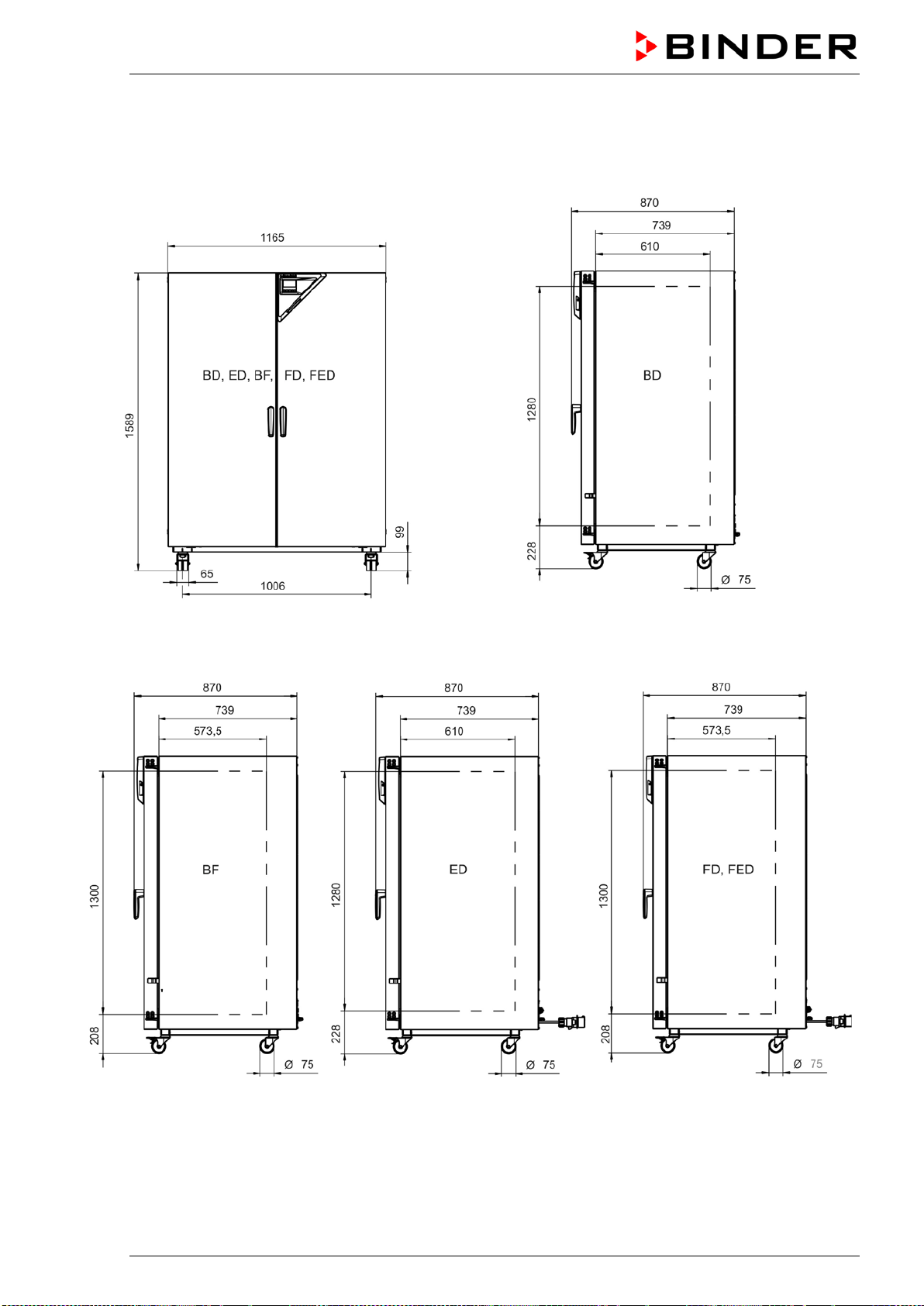
BD / BF / ED / FD / FED (E3.1) 03/2019 page 87/106
16.14 Dimensions size 720
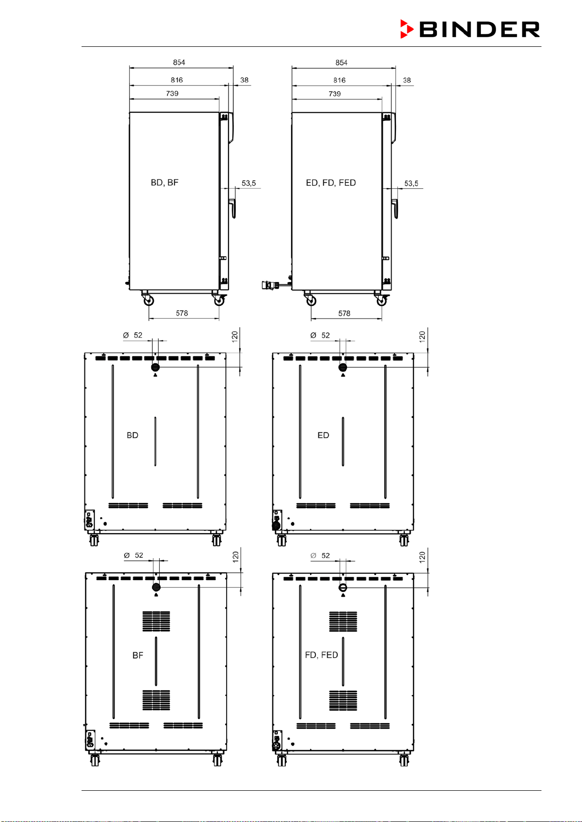
BD / BF / ED / FD / FED (E3.1) 03/2019 page 88/106

BD / BF / ED / FD / FED (E3.1) 03/2019 page 89/106
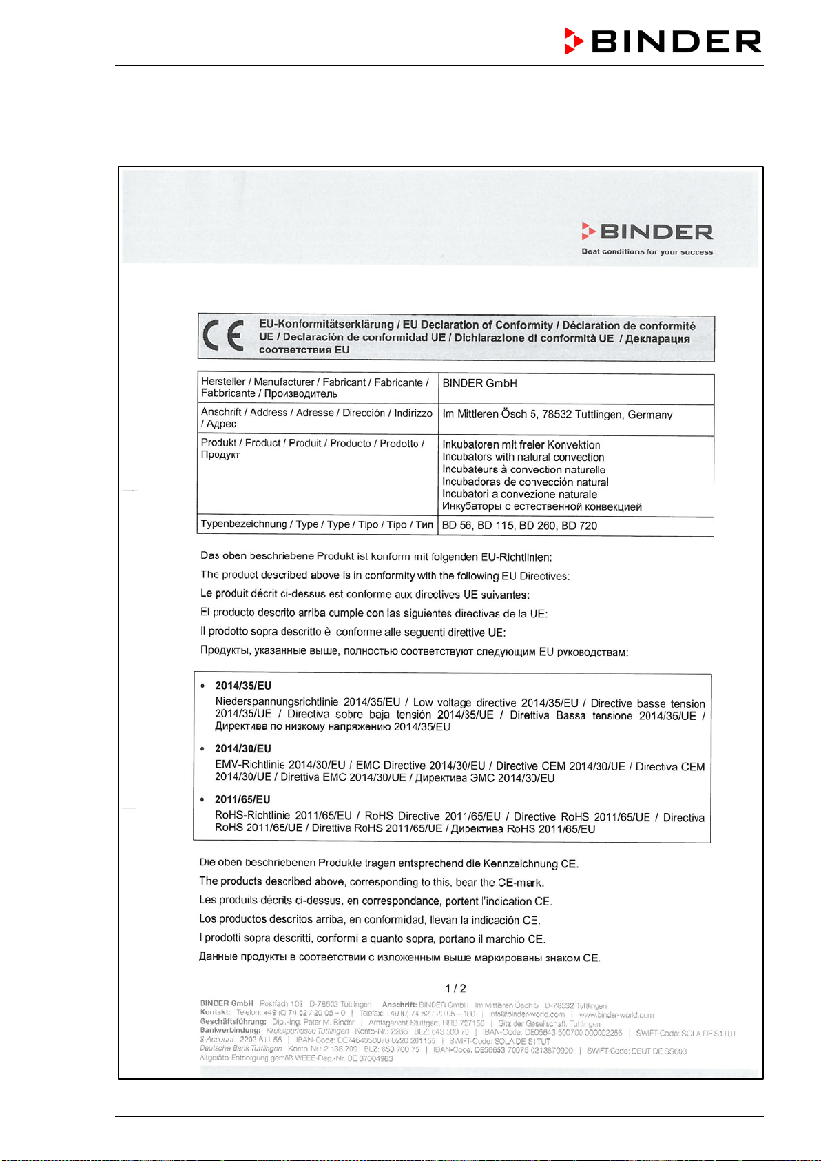
BD / BF / ED / FD / FED (E3.1) 03/2019 page 90/106
17. Certificates and declarations of conformity
17.1 EU Declaration of Conformity for BD

BD / BF / ED / FD / FED (E3.1) 03/2019 page 91/106
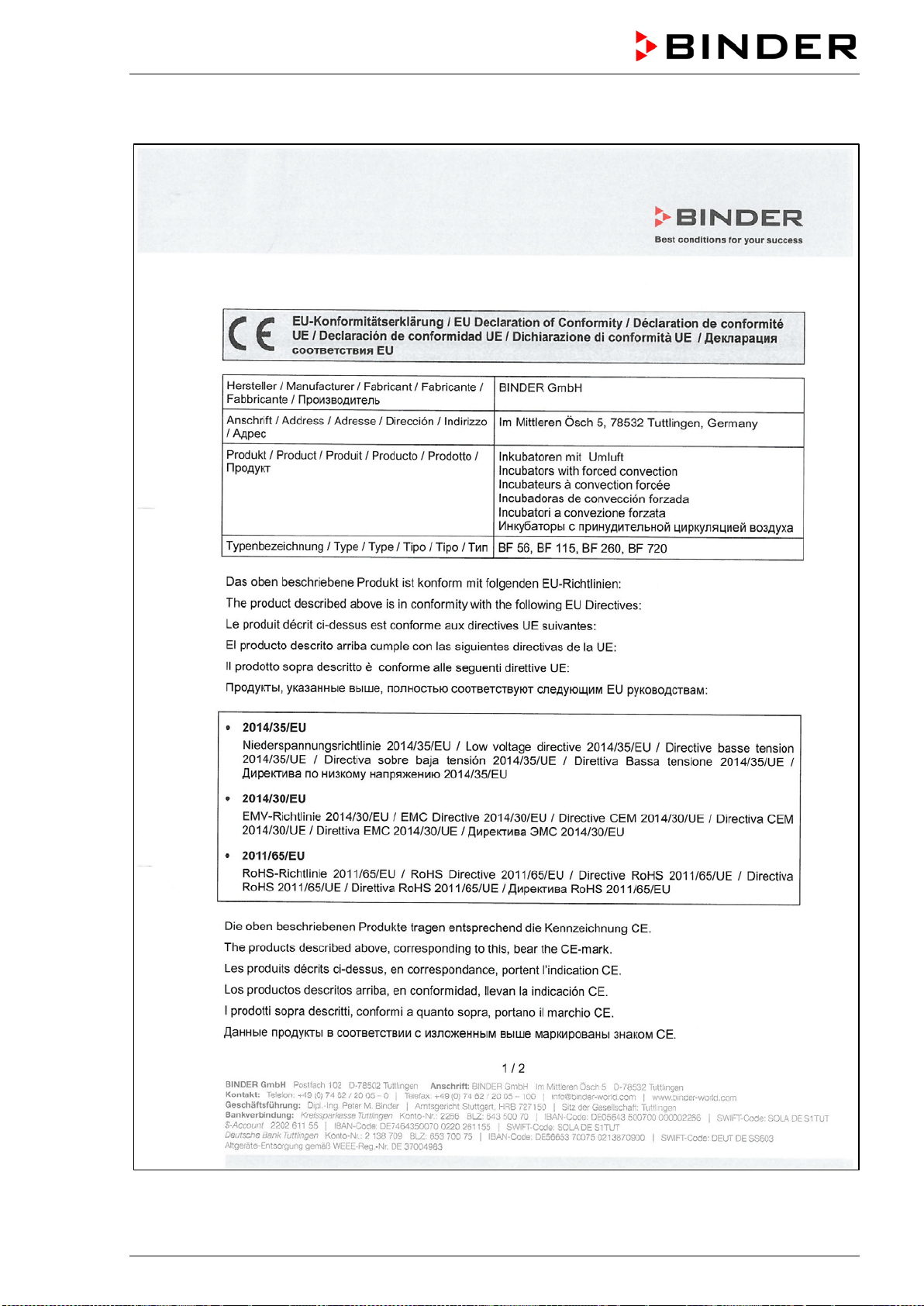
BD / BF / ED / FD / FED (E3.1) 03/2019 page 92/106
17.2 EU Declaration of Conformity for BF
BD / BF / ED / FD / FED (E3.1) 03/2019 page 93/106
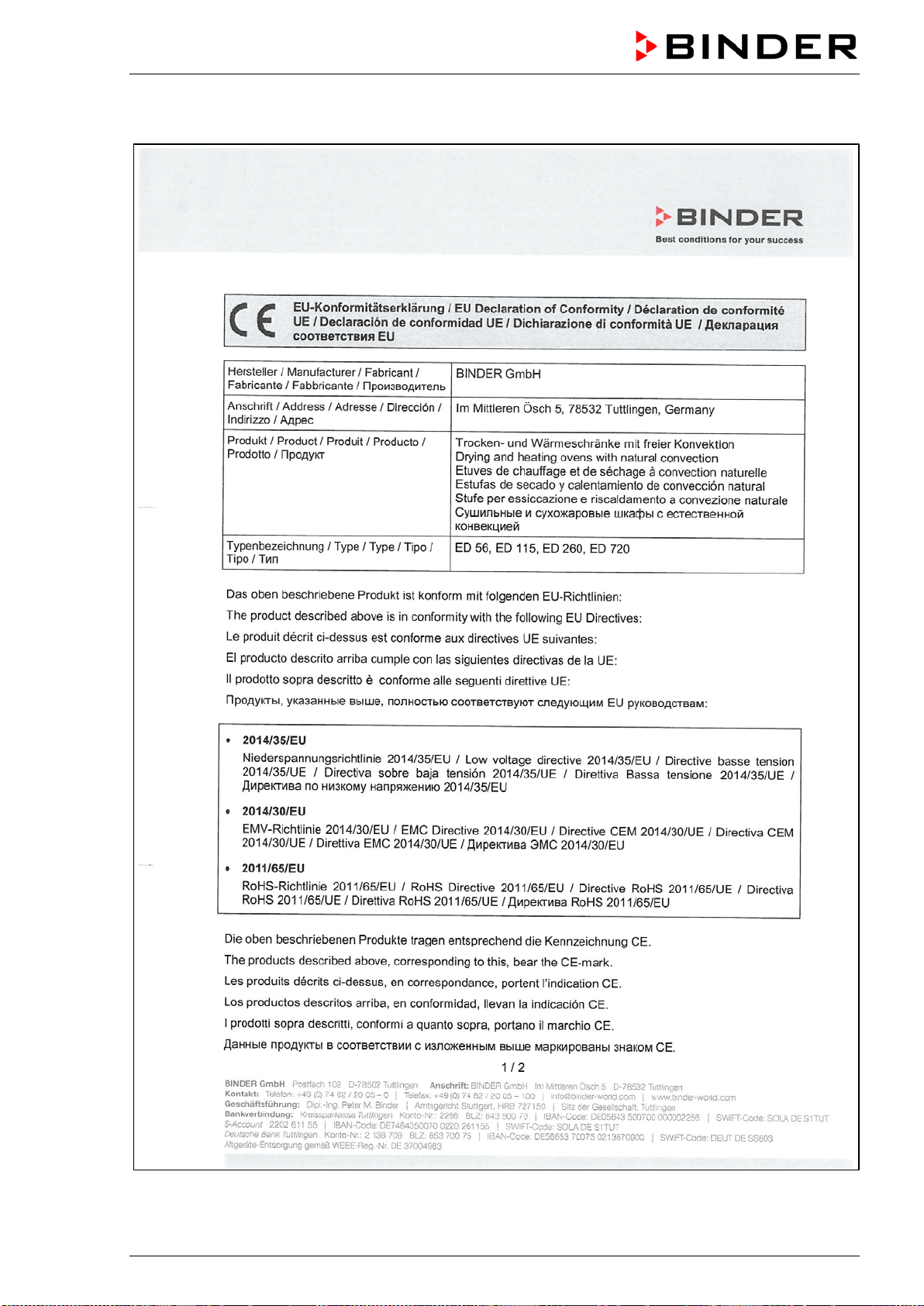
BD / BF / ED / FD / FED (E3.1) 03/2019 page 94/106
17.3 EU Declaration of Conformity for ED

BD / BF / ED / FD / FED (E3.1) 03/2019 page 95/106
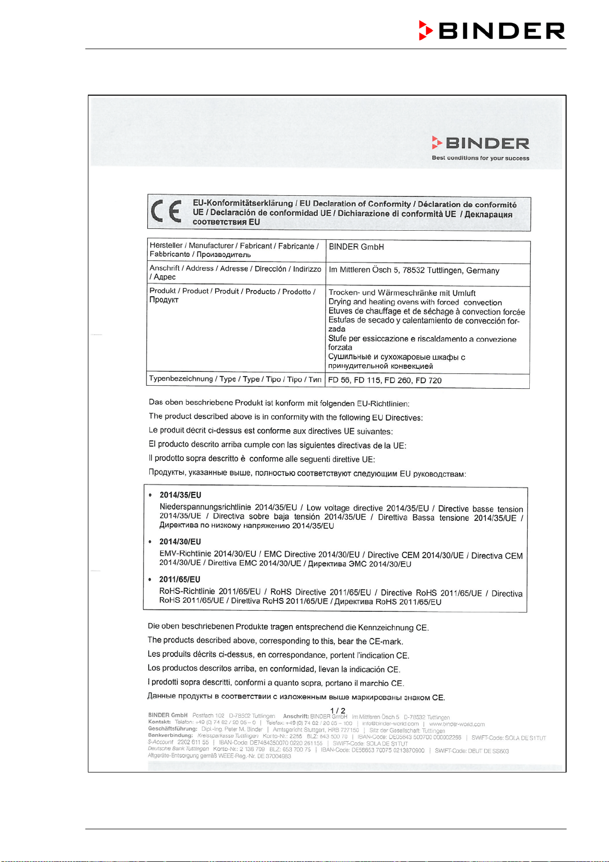
BD / BF / ED / FD / FED (E3.1) 03/2019 page 96/106
17.4 EU Declaration of Conformity for FD

BD / BF / ED / FD / FED (E3.1) 03/2019 page 97/106

BD / BF / ED / FD / FED (E3.1) 03/2019 page 98/106
17.5 EU Declaration of Conformity for FED
BD / BF / ED / FD / FED (E3.1) 03/2019 page 99/106
BD / BF / ED / FD / FED (E3.1) 03/2019 page 100/106
18. Product registration
BD / BF / ED / FD / FED (E3.1) 03/2019 page 101/106
19. Contamination clearance certificate
19.1 For chambers located outside the USA and Canada
Declaration with regard to safety and health
Erklärung zur Sicherheit und gesundheitlichen Unbedenklichkeit
The German Ordinance on Hazardous Substances (GefStofV), and the regulations regarding safety at
the workplace, require that this form be filled out for all products that are returned to us, so that the safety
and health of our employees can be warranted.
Die Sicherheit und Gesundheit unserer Mitarbeiter, die Gefahrstoffverordnung GefStofV und die Vorschriften zur
Sicherheit am Arbeitsplatz machen es erforderlich, dass dieses Formblatt für alle Produkte, die an uns zurückge-
schickt wird.
In the absence of a completely filled out form, a repair is not possible.
Ohne Vorliegen des vollständig ausgefüllten Formblattes ist eine Reparatur nicht möglich.
• A completely filled out form should be transmitted by Fax (+49 (0) 7462 2005 93555) or by letter in
advance to us, so that this information is available before the equipment/component part arrives. A
second copy of this form should accompany the equipment/component part. Eventually the carrier
should be informed.
Eine vollständig ausgefüllte Kopie dieses Formblattes soll per Telefax (Nr. +49 (0) 7462 2005 93555) oder Brief
vorab an uns gesandt werden, so dass die Information vorliegt, bevor das Gerät/Bauteil eintrifft. Eine weitere Ko-
pie soll dem Gerät/Bauteil beigefügt sein. Ggf. ist auch die Spedition zu informieren.
•
Incomplete information or non-conformity with this procedure will inevitably lead to substantial delays
in processing. We hope you will have understanding for this measure, which lies outside of our area of
influence, and that you will help us to speed up this procedure.
Unvollständige Angaben oder Nichteinhalten dieses Ablaufs führen zwangsläufig zu beträchtlichen Verzögerun-
gen in der Abwicklung. Bitte haben Sie Verständnis für Maßnahmen, die außerhalb unserer Einflussmöglichkeiten
liegen und helfen Sie mit, den Ablauf beschleunigen.
•
Please fill out this form completely.
Bitte unbedingt vollständig ausfüllen!
1. Chamber/ component part / type: / Gerät / Bauteil / Typ:
2. Serial No./ Serien-Nr.:
3. Details about utilized substances / biological substances / Einzelheiten über die eingesetzten
Substanzen/biologische Materialien:
3.1 Designations / Bezeichnungen:
a) ____________________________________________________________________________
b) ____________________________________________________________________________
c) ____________________________________________________________________________
3.2 Safety measures required for handling these substances / Vorsichtsmaßnahmen beim Um-
gang mit diesen Stoffen:
a) ____________________________________________________________________________
b) ____________________________________________________________________________
c) ____________________________________________________________________________

BD / BF / ED / FD / FED (E3.1) 03/2019 page 102/106
3.3 Measures to be taken in case of skin contact or release into the atmosphere / Maßnahmen
bei Personenkontakt oder Freisetzung:
a) ____________________________________________________________________________
b) ____________________________________________________________________________
c) ____________________________________________________________________________
d) ____________________________________________________________________________
3.4 Other important information that must be taken into account / Weitere zu beachtende und
wichtige Informationen:
a) ____________________________________________________________________________
b) ____________________________________________________________________________
c) ____________________________________________________________________________
4. Declaration on the risk of these substances (please checkmark the applicable items) /
Erklärung zur Gefährlichkeit der Stoffe (bitte Zutreffendes ankreuzen) :
4.1 For non toxic, non radioactive, biologically harmless materials / für nicht giftige, nicht radio-
aktive, biologisch ungefährliche Stoffe:
We herewith guarantee that the above-mentioned chamber / component part… /
Wir versichern,
dass o.g. Gerät/Bauteil...
Has not been exposed to or contains any toxic or otherwise hazardous substances /
weder giftige noch
sonstige gefährliche Stoffe enthält
oder solche anhaften.
That eventually generated reaction products are non-toxic and also do not represent a hazard /
auch
evtl. entstandene Reaktionsprodukte weder giftig sind noch sonst eine Gefährdung darstellen.
Eventual residues of hazardous substances have been removed /
evtl. Rückstände von Gefahrstoffen
entfernt wurden.
4.2 For toxic, radioactive, biologically harmful or hazardous substances, or any other ha-
zardous materials / für giftige, rad
ioaktive, biologisch bedenkliche bzw. gefährliche Stoffe oder
anderweitig gefährliche Stoffe.
We herewith guarantee that … /
Wir versichern, dass …
The hazardous substances, which have come into contact with the above-mentioned equip-
ment/component part, have been completely listed under item 3.1 and that all information in this re-
gard is complete /
die gefährlichen Stoffe, die mit dem o.g. Gerät/Bauteil in Kontakt kamen, in 3.1 aufgelistet
sind und alle Angaben vollständig sind.
That the chamber /component part has not been in contact with radioactivity /
das Gerät/Bauteil nicht mit
Radioaktivität in Berührung kam
5. Kind of transport / transporter / Transportweg/Spediteur:
Transport by (means and name of transport company, etc.) Versendung durch (Name Spediteur o.ä.)
___________________________________________________________________________________
Date of dispatch to BINDER GmbH / Tag der Absendung an BINDER GmbH:
___________________________________________________________________________________
BD / BF / ED / FD / FED (E3.1) 03/2019 page 103/106
We herewith declare that the following measures have been taken / Wir erklären, dass folgende
Maßnahmen getroffen wurden:
Hazardous substances were removed from the chamber / component part, so that no hazard exists for
corresponding persons in the handling or repair of these items /
das Gerät/Bauteil wurde von Gefahrstof-
fen befreit, so dass bei Handhabung/Reparaturen für die betreffenden Person keinerlei Gefährdung besteht
The chamber was securely packaged and properly identified /
das Gerät wurde sicher verpackt und voll-
ständig gekennzeichnet.
Information about the hazardousness of the shipment (if required) has been provided to the transpor-
ter /
der Spediteur wurde (falls vorgeschrieben) über die Gefährlichkeit der Sendung informiert.
We herewith commit ourselves and guarantee that we will indemnify BINDER GmbH for all damages that
are a consequence of incomplete or incorrect information provided by us, and that we will exempt
BINDER GmbH from eventual damage claims by third parties./
W
ir versichern, dass wir gegenüber BINDER
für jeden Schaden, der durch unvollständige und unrichtige Angaben entsteht, haften und BINDER gegen eventuell
entstehende Schadenansprüche Dritter freistellen.
We are aware that, in accordance with Article 823 of the German Civil Code (BGB), we are directly liable
with regard to third parties, in this instance especially the employees of BINDER GmbH, who have been
entrusted with the handling / repair of the chamber / component. /
Es ist uns bekannt, dass wir gegenüber
Dritten –
hier insbesondere mit der Handhabung/Reparatur des Geräts/des Bauteils betraute Mitarbeiter der Firma
BINDER - gemäß §823 BGB direkt haften
Name: _______________________________________________________________________
Position: _______________________________________________________________________
Date /
Datum: _______________________________________________________________________
Signature / Unterschrift: ______________________________________________________________
Company stamp /
Firmenstempel:
Equipment that is returned to the factory for repair must be accompanied by a completely filled
out contamination clearance certificate. For service and maintenance works on site, such a
contamination clearance certificate must be submitted to the service technician before the
start of the works. No repair or maintenance of the equipment is possible, without a properly
filled out contamination clearance certificate.

BD / BF / ED / FD / FED (E3.1) 03/2019 page 104/106
19.2 For chambers located in the USA and Canada
Product Return Authorization Request
Please complete this form and the Customer Decontamination Declaration (next 2 pages) and attach the
required pictures. E-mail to: IDL_SalesOrderProcessing_USA@binder-world.com
After we have received and reviewed the complete information we will decide on the issue of a RMA
number. Please be aware that size specifications, voltage specifications as well as performance specifi-
cations are available on the internet at www.binder-world.us at any time.
Take notice of shipping laws and regulations.
Please fill:
Reason for return request Duplicate order
Duplicate shipment
Demo
Page one completed by sales
Power Plug / Voltage 115V / 230 V / 208 V / 240V
Size does not fit space
Transport Damage
Shock watch tripped? (pictures)
Other (specify below)
_____________________
Is there a replacement PO? Yes No
If yes -> PO #
If yes -> Date PO placed
Purchase order number
BINDER model number
BINDER serial number
Date chamber was received
Was the chamber unboxed? Yes No
Was the chamber plugged
in?
Yes No
Was the chamber in opera-
tion?
Yes No
Pictures of chamber at-
tached?
Pictures of Packaging at-
tached?
Yes No
Yes No
Pictures have to be attached!
Customer Contact Information Distributor Contact Information
Name
Company
Address
Phone
E-mail
BD / BF / ED / FD / FED (E3.1) 03/2019 page 105/106
Customer (End User) Decontamination Declaration
Health and Hazard Safety declaration
To protect the health of our employees and the safety at the workplace, we require that this form is com-
pleted by the user for all products and parts that are returned to us. (Distributors or Service Organizations
cannot sign this form)
NO RMA number will be issued without a completed form. Products or parts returned to our
NY warehouse without a RMA number will be refused at the dock.
A second copy of the completed form must be attached to the outside of the shipping box.
1. Chamber/ component part / type
:
2. Serial No.
3. List any exposure to hazardous liquids, gasses or substances and radioactive material
3.1 List with MSDS sheets attached where available or needed
(if there is not enough space available below, please attach a page):
a) ____________________________________________________________________________
b) ____________________________________________________________________________
c) ____________________________________________________________________________
3.2 Safety measures required for handling the list under 3.1
a) ____________________________________________________________________________
b) ____________________________________________________________________________
c) ____________________________________________________________________________
3.3 Measures to be taken in case of skin contact or release into the atmosphere
:
a) ____________________________________________________________________________
b) ____________________________________________________________________________
c) ____________________________________________________________________________
d) ____________________________________________________________________________
3.4 Other important information that must be considered
:
a) ____________________________________________________________________________
b) ____________________________________________________________________________
c) ____________________________________________________________________________
BD / BF / ED / FD / FED (E3.1) 03/2019 page 106/106
4. Declaration of Decontamination
For toxic, radioactive, biologically and chemically harmful or hazardous substances, or any other
hazardous materials.
We hereby guarantee that
4.1 Any hazardous substances, which have come into contact with the above-mentioned equipment /
component part, have been completely listed under item 3.1 and that all information in this regard is
complete
.
4.2 That the chamber /component part has not been in contact with radioactivity
4.3 Any Hazardous substances were removed from the chamber / component part, so that no hazard
exists for a persons in the shipping, handling or repair of these returned chamber
4.4 The chamber was securely packaged in the original undamaged packaging and properly identified
on the outside of the packaging material with the chamber designation, the RMA number and a
copy of this declaration.
4.5 Shipping laws and regulations have not been violated.
I hereby commit and guarantee that we will indemnify BINDER Inc. for all damages that are a
consequence of incomplete or incorrect information provided by us, and that we will indemnify
and hold harmless BINDER Inc. from eventual damage claims by third parties.
Name: _______________________________________________________________________
Position: _______________________________________________________________________
Company: _______________________________________________________________________
Address: _______________________________________________________________________
Phone #: _______________________________________________________________________
Email: _______________________________________________________________________
Date: _______________________________________________________________________
Signature: _______________________________________________________________________
Equipment returned to the NY warehouse for repair must be accompanied by a completed
customer decontamination declaration. For service and maintenance works on site, such a
customer decontamination declaration must be submitted to the service technician before the
start of work. No repair or maintenance of the equipment is possible without a completed form.