Loading ...
Loading ...
Loading ...
6 | Technical Characteristics and Dimensions
6 720 608 992 (2011/12)
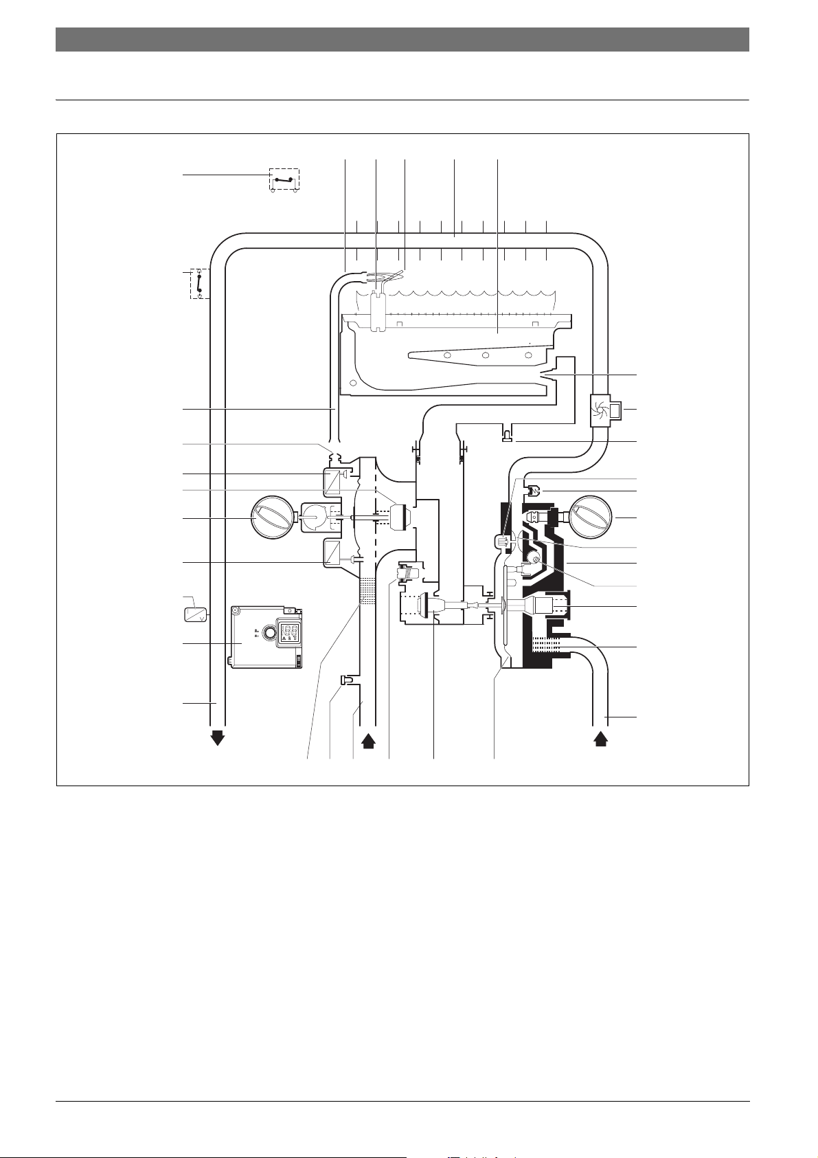
2.6 Functional diagram of the heater
Fig. 2 Functional diagram
1 Pilot burner
2 Ignition Electrode
3 Ionisation probe
4 Heat exchanger
5 Main burner
6 Injector
7a Burner pressure test point
7b Gas inlet pressure test point
8 Slow ignition valve
9 Venturi
10 Temperature/volume selector
11 Water valve
12 Plunger
13 Water flow regulator
14 Water filter
15 Hydrogenerator
16 Cold water pipe
17 Diaphragm
18 Main gas valve
19 Maximum gas adjusting screw
20 Gas supply pipe
21 Gas filter
22 Hot water pipe
23 Ignition unit
24 Temperature sensor
25 Servo valve
26 Power selector
27 Gas valve
28 Pilot valve
29 Pilot injector
30 Pilot gas pipe
31 Overtemperature switch
32 Flue gas safety device
33 Relief Valve/Drain screw
12
3
4
5
6
8
9
10
15
7a
11
12
13
14
16
171819207b21
23
22
25
24
26
27
28
29
30
31
32
33
6720608992-05.1V
Loading ...
Loading ...
Loading ...