Loading ...
Loading ...
Loading ...
Commissioning | 15
6 720 608 992 (2011/12)
6 Commissioning
6.1 Inlet pressure adjustment
Burner pressures have been adjusted in the factory,
however adjustment may be required upon installation.
Attach a manometer to the inlet pressure test point
located on the gas inlet pipe.
Inlet gas pressure should be adjusted at the appliance
regulator to 1.13 kPa for Natural Gas and 2.75 kPa for LP
gas.
These measurements must be set while the unit is
operating.
6.2 Burner pressure adjustment
Accessing the adjusting screw
B Remove the front cover from the heater (see 4.3).
Connecting the manometer
B loosen the burner test point captive screw (Fig. 16).
B Connect the manometer to the burner pressure
measuring point.
Fig. 16 Pressure measurement point
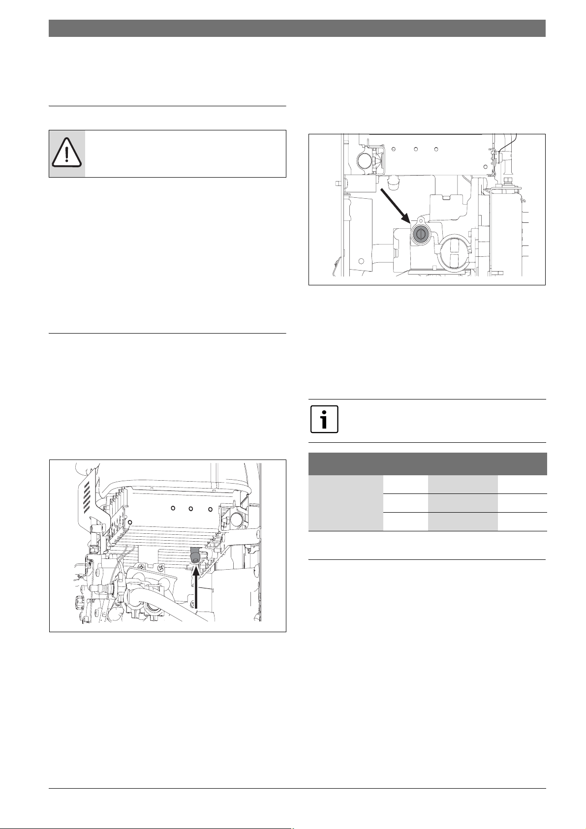
Maximum gas flow adjustment
B Remove the seal from the adjusting screw (Fig. 17).
B Turn on the heater with the gas selector set to the left
(maximum position).
Fig. 17 Maximum gas flow adjusting screw
B Open various hot water taps.
B Using the adjusting screw (Fig. 17), regulate the gas
pressure until the values indicated in the table 6 are
achieved.
B Seal the adjusting screw once again.
Minimum gas flow adjustment
6.3 Conversion to a different type of gas
Only use original conversion parts.
The conversion must only be performed by a qualified
technician. Original conversion kits are supplied with
assembly instructions.
DANGER:
The following procedures must only be
performed by a qualified technician.
6720607418-01.3V
The minimum gas flow adjustment is
performed automatically after the
adjustment of the maximum gas flow.
Natural gas H LP gas
MAX Burner
Pressure
(kPa)
GWH10 0.69 2.00
GWH13
0.66 1.90
GWH16
0.44 2.20
Table 6 Burner pressure
6720607418-02.2V
Loading ...
Loading ...
Loading ...