User Manual Viking VUBV515GSS 15" Beverage Center (VUBV)
Installation
Side-by-Side Installation
OTHER SITE REQUIREMENTS
Side-by-Side Installation
Units must operate from separate, properly grounded electrical receptacles placed according to each unit’s electrical specifi cations requirements.
Cutout width for a side-by-side installation is the total of the widths listed under Cutout Dimensions in each unit’s Installation Guide.
Each door can be opened individually (one at a time) without interference.

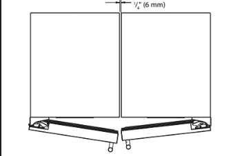
However, to ensure unobstructed door swing (opening both doors at the same time), 1/4” (6.4 mm) of space needs to be maintained between the units.
Hinge-by-Hinge Installation (Mullion)
When installing two units hinge-by-hinge, 13/16” (22 mm) is required for integrated models. Additional space may be needed for any knobs, pulls or handles installed. 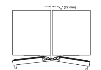
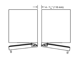
Stainless steel models which include the standard stainless handle will require 4-9/16” (116 mm) to allow both doors to open to 90° at the same time.
Anti-Tip Bracket
Use one of the methods below to secure the unit
CABINET/COUNTER ANTI-TIP INSTALLATION (For built-in applications)
1. Slide unit out so screws on front of unit are easily accessible.
2. Remove the two screws from the front of the unit.
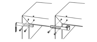
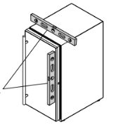
3. Bend bracket along one of the perforations to allow attachment to the desired adjoining surface.
4. Gently push unit into position. Be careful not to entangle the electrical cord or water line, if applicable.
5. Check to be sure the unit is level from front to back and side to side. Make any necessary adjustments. The unit’s top surface should be approximately 1⁄8” (3 mm) below the countertop.
6. Secure bracket to adjoining surface.
FLOOR MOUNTED ANTI-TIP INSTALLATION (For free-standing applications)
1. Locate two anti-tip brackets included with the kit.
2. Place the unit into the area where it will be installed. Check the door, sides, and top for a proper fi t. Also test to make sure the door opens and closes freely.
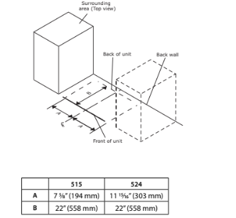
3. Remove grille and place a mark on the fl oor at the front of the unit. Also place a mark on the fl oor in the center of the unit.
4. Remove the unit. Using a square, extend center line “B” see chart below). This line serves as the back edge for the anti-tip brackets. From the center line, measure “A” to the left and right. This line is the outer edge of each bracket.
5. Place the anti-tip brackets on the fl oor against the line drawn for the outer edge. Mark spots for the screw holes.
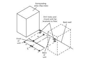
6. Use a 1/8” drill to make two starter holes and fasten the anti-tip brackets to the fl oor using the screws provided.
7. Place the unit back into position, making sure the feet engage the anti-tip brackets properly. Check the alignment of the lines made on the fl oor in step 3 with the position of the front feet to ensure proper positioning.
LEVELING INFORMATION
1. Use a level to confi rm the unit is level. Level should be placed along top edge and side edge as shown.
2. If the unit is not level, adjust the legs on the corners of the unit as necessary.

3. Confi rm the unit is level after each adjustment and repeat the previous steps as needed.
INSTALLATION TIP
If the room fl oor is higher than the fl oor in the cutout opening, adjust the rear legs to achieve a total unit rear height of 1⁄8” (3 mm) less than opening’s rear height. Shorten the unit height in the front by adjusting the front legs. This allows the unit to be gently tipped into the opening. Readjust the front legs to level the unit after it is correctly positioned in the opening.
1. Plug in the power/electrical cord.
2. Gently push the unit into position. Be careful not to entangle the cord or water and drain lines, if applicable.
3. Re-check the leveling, from front to back and side to side. Make any necessary adjustments. The unit’s top surface should be approximately 1⁄8” (3 mm) below the countertop.
4. Install the anti-tip bracket.
5. Remove interior packing material and wipe out the inside of the unit with a clean, water-dampened cloth.
Door Adjustments
DOOR ALIGNMENT AND ADJUSTMENT
Align and adjust the door if it is not level or not sealing properly. If the door is not sealed, the unit may not cool properly, or excessive frost or condensation may form in the interior.
NOTICE
Properly aligned, the door’s gasket should be fi rmly in contact with the cabinet all the way around the door (no gaps). Carefully examine the door’s gasket to ensure that it is fi rmly in contact with the cabinet. Also make sure the door gasket is not pinched on the hinge side of the door.

Do not attempt to use the door to raise or pivot your unit. This would put excessive stress on the hinge system.
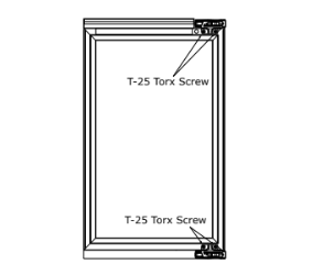
Alignment and Adjustment Procedure
- Open door and remove gasket near the hinges.
- Using a T-25 Torx bit, loosen each pair of Torx head screws both the upper and lower hinge plates.
- Square and align door as necessary.
- Tighten Torx head screws on hinge.
- Reinstall gasket into the channel starting at the corner.
REVERSING THE DOOR
1. Open door.
2. Using T-25 Torx bit loosen screw #1 and remove screw #2 on top and bottom hinge. Slide and remove the door from the unit.

Note: One hinge includes a metal spacer. Spacer must be used with that hinge when reversing the door.
3. Remove caps from screw heads on opposite side (2 on top and on bottom). Using #2 Phillips bit, remove the 4 underlying screws. Reinstall the screws and caps on the opposite side.
4. Partially install screw #1 in the outer most holes on top and bottom. Rotate door 180o, align hinge over screw #1 and slide/seat into position. Reinstall screw #2 on top and bottom. Tighten both screws and install hinge cover.
Align and adjust the door:
Align and adjust the door (see DOOR ALIGNMENT AND ADJUSTMENT).
Operating Instructions
First Use
Initial startup requires no adjustments. When plugged in, the unit will begin operating under the factory default settings. If the unit was turned off during installation, simply press and the unit will immediately switch on. To turn the unit off , press .
If the temperature displayed is diff erent than selected, the unit is progressing towards the selected temperature. Time to reach set point varies based upon ambient temperature, temperature of product loaded, door openings, etc. Viking recommends allowing the unit to reach set points before loading.
NOTICE: Temperature displayed refl ects actual temperature inside unit.
Control Operation

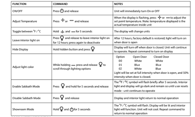
CONTROL FUNCTION GUIDE
DOOR ALERT NOTIFICATION
When the door is left open for more than 5 minutes:
- A tone will sound for several seconds every minute
- will appear in display
- Closed door to silence alert and reset
Interior Adjustments
All 5 Series models feature side mounted rack supports with adjustment positions.
All Beverage Centers ship with 2 wine racks and 2 Storage bins - Remove and reposition as desired.
WINE RACK ADJUSTMENT
Wine Rack Removal
1. Fully extend empty rack
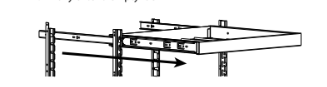
2. Firmly grasp both sides of rack and lift front end of rack slightly (about 1⁄4 ”) to center the pin in the slot

3. Pull rack towards you until all pins are clear of the slots. If only repositioning the rack, do not remove completely go to “Rack Installation” Step 2.
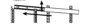
4. Slightly tilt one side. Gently pull rack towards you to remove rack from unit.

Note: Take care when removing rack to avoid scratching interior of unit.
5. Once removed, retract the slides.
Note: The slides on the rack have a thin coating which is used to block moisture and provide lubrication. Use care when handling.
Wine Rack Installation
1. Insert empty rack into unit with one side tilted slightly downward until back pin is between front and rear rail supports.
2. Tilt rack back to horizontal and line up 2 back pins with back slots.
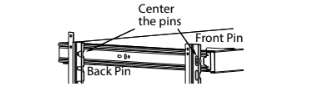
3. Line up 2 back pins with 2 back slots and 2 front pins with 2 front slots.
4. Continue inserting rack until all four pins are fully inserted. Front of rack will set down slightly into the front slots and be locked into position.
Common Food and Wine Matches
A Toast to Wine Truths
Like the grapes themselves, many wine myths have been cultivated over the centuries.
Myth 1: Most wines taste better when aged.
Truth: In fact, less than 5% of wines produced today are meant to be aged. Most wines are crafted to be consumed within the fi rst one to two years.
Myth 2: Wines should be uncorked and decanted allowing them to “breathe.”
Truth: To breathe or not breathe? While it is better to allow a young tannic Red to breathe in a glass or decanter to soften the tannins, an old Red reaches a stage in its life where it should be enjoyed soon after opening. Allow an old Red to breathe for a short time to dissipate any off odors. Most white wines can be served, ideally, 10-15 minutes after opening.
Myth 3: When age worthy wines peak, they must be consumed almost immediately.
Truth: Most great wines reach a plateau period rather than a peak. Great Bordeaux’s may have as much as a 10-year plateau before fading.
Myth 4: Wine color does not change with aging.
Truth: As red wines age they get lighter in color while whites get darker.
The Cork: A Mystery on Its Own
Cork Presentation. The ritual of the presentation of the cork has a rich and fascinating history dating back to the late s. A phylloxera (root louse) devastation to the vineyards severely limited the supply of great wines. Restaurateurs would remove labels on inferior wines and replace them with labels from superior wines. This made it necessary for patrons to protect themselves by checking the branding on the cork to ensure that what they ordered was, in fact, what they were served.
When presented with a cork today, feel it to check for its integrity, read and match the branding on the cork to the bottle and set it aside. There is little to be learned from the cork. The proof is in the wine.
Corked” wines. If you’ve ever had a wine that smelled or tasted of mold, you’ve experienced a wine that may have been “corked.” Today, between fi ve and eight percent of wines are tainted with Trichloroanisole (TCA). This substance, found naturally in plants and trees, is imparted to the wine through the cork. Corked wines are a major concern for winemakers as it destroys millions of cases per year and puts reputations at stake. Amazing as it may seem, twist-off caps may off er a better alternative; many great wineries in California, Australia and New Zealand are pioneering the trend.
Maintenance
Cleaning
Stainless Models
Stainless door panels, handles and frames can discolor when exposed to chlorine gas, pool chemicals, saltwater or cleaners with bleach.
Keep your stainless unit looking new by cleaning with a good quality all-in-one stainless steel cleaner and polish monthly. For best results use Claire® Stainless Steel Polish and Cleaner. Comparable products are acceptable. Frequent cleaning will remove surface contamination that could lead to rust. Some installations may require cleaning weekly.
Do not clean with steel wool pads.
Do not use stainless steel cleaners or polishes on any glass surfaces.
Clean any glass surfaces with a non-chlorine glass cleaner.
Do not use cleaners not specifi cally intended for stainless steel on stainless steel surfaces (this includes glass, tile, and counter cleaners).
If any surface discoloring or rusting appears, clean it quickly with Bon-Ami® or Barkeepers Friend Cleanser® and a nonabrasive cloth. Always clean with the grain. Always fi nish with Claire® Stainless Steel Polish and Cleaner or comparable product to prevent further problems.
Using abrasive pads such as ScotchBriteTM will cause the graining in the stainless steel to become blurred.
Rust not cleaned up promptly can penetrate the surface of the stainless steel and complete removal of the rust may not be possible.
Integrated Models
To clean integrated panels, use household cleaner per the cabinet manufacturer’s recommendations.
INTERIOR CLEANING
Disconnect power to the unit.
Clean the interior and all removed components using a mild nonabrasive detergent and warm solution applied with a soft sponge or non-abrasive cloth.
Rinse the interior using a soft sponge and clean water.
Do not use any solvent-based or abrasive cleaners. These types of cleaners may transfer taste and/or odor to the interior products and damage or discolor the interior.
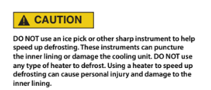
DEFROSTING
Under normal conditions this unit does not require manual defrosting. Minor frost on the rear wall or visible through the evaporator plate vents is normal and will melt during each cycle.
If there is excessive build-up of 1/4” (6 mm) or more, manually defrost the unit.
Ensure the door is closing and sealing properly.
High ambient temperature and excessive humidity can also produce frost.
NOTICE
The drain pan was not designed to capture the water created when manually defrosting. To prevent water from overfl owing the drain pan and possibly damaging water sensitive fl ooring, the unit must be removed from cabinetry.
To defrost:
- Disconnect power to the unit.
- Remove all products from the interior
- Prop the door in an open position (2 in. [50 mm] minimum).
- Allow the frost to melt naturally.
- After the frost melts completely, clean the interior and all removed components. (See INTERIOR CLEANING).
- When the interior is dry, reconnect power and turn unit on.
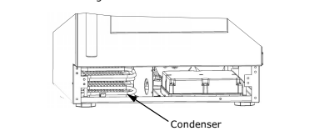
Cleaning Condenser
INTERVAL - EVERY SIX MONTHS
To maintain operational effi ciency, keep the front grille free of dust and lint, and clean the condenser when necessary.
Depending on environmental conditions, more or less frequent cleaning may be necessary.

NOTICE
DO NOT use any type of cleaner on the condenser unit. Condenser may be cleaned using a vacuum, soft brush, or compressed air.
1. Remove the grille. See GRILLE INSTALLATION).
2. Clean the condenser coil using a soft brush or vacuum cleaner.
3. Install the grille.
Extended Non-Use
VACATION/HOLIDAY, PROLONGED SHUTDOWN
The following steps are recommended for periods of extended non-use:
- Remove all consumable content from the unit.
- Disconnect the power cord from its outlet/socket and leave it disconnected until the unit is returned to service.
- If any ice is visible inside the unit, allow ice to thaw naturally.
- Clean and dry the interior of the unit. Ensure all water has been removed from the unit.
- The door must remain open to prevent formation of mold and mildew. Open door a minimum of 2” (50 mm) to provide the necessary ventilation.
WINTERIZATION
If the unit will be exposed to temperatures of 40oF (5oC) or less, the steps above must be followed.
For questions regarding winterization, please call Viking Preferred Service at (888) 845-4641.
Troubleshooting
BEFORE CALLING FOR SERVICE
If you think your product is malfunctioning, read the CONTROL OPERATION section to clearly understand the function of the control.
If the problem persists, read the NORMAL OPERATING SOUNDS and TROUBLESHOOTING GUIDE sections below to help you quickly identify common problems and possible causes and remedies. Most often, this will resolve the problem without the need to call for service.
IF SERVICE IS REQUIRED
If you do not understand a troubleshooting remedy, or your product needs service, contact Viking Preferred Service directly at (888) 845-4641.
When you call, you will need your product Model and Serial Numbers. This information appears on the Model and Serial number plate located on the upper right or rear wall of the interior of your product.
NORMAL OPERATING SOUNDS
All models incorporate rigid foam insulated cabinets to provide high thermal effi ciency and maximum sound reduction for its internal working components. Despite this technology, your model may make sounds that are unfamiliar.
Normal operating sounds may be more noticeable because of the unit’s environment. Hard surfaces such as cabinets, wood, vinyl or tiled fl oors and paneled walls have a tendency to refl ect normal appliance operating noises.
Listed below are common refrigeration components with a brief description of the normal operating sounds they make. NOTE: Your product may not contain all the components listed.
- Compressor: The compressor makes a hum or pulsing sound that may be heard when it operates.
- Evaporator: Refrigerant fl owing through an evaporator may sound like boiling liquid.
- Condenser Fan: Air moving through a condenser may be heard.
- Automatic Defrost Drain Pan: Water may be heard dripping or running into the drain pan when the unit is in the defrost cycle.
TROUBLESHOOTING GUIDE

Troubleshooting - What to check when problems occur:
1. Interior Light Does Not Illuminate
- If the unit is cooling, it may be in Sabbath mode.
2. Light Remains on When Door Is Closed.
- Turn off light switch if equipped.
- Adjust light actuator bracket on bottom of door.
3. Unit Develops Frost on Internal Surfaces.
- Ensure the door is closing and sealing properly.
4. Unit Develops Condensation on External Surfaces.
- The unit is exposed to excessive humidity.
- Moisture will dissipate as humidity levels decrease.
5. Product is Not Cold Enough
- Air temperature does not indicate product temperature. See CHECKING PRODUCT TEMPERATURE below.
- Adjust the temperature to a cooler set point.
- Ensure unit is not located in excessive ambient temperatures or in direct sunlight.
- Ensure the door is closing and sealing properly.
- Ensure the interior light has not remained on too long.
- Ensure nothing is blocking the front grille, found at the bottom of the unit.
- Ensure the condenser coil is clean and free of any dirt or lint build-up.
CHECKING PRODUCT TEMPERATURE

To check the actual product temperature in the unit:
- Partially fi ll a plastic (nonbreakable) bottle with water.
- Insert an accurate thermometer.
- Tighten the bottle cap securely.
- Place the bottle in the desired area for 24 hours.
- Avoid opening the unit during the testing period.
- After 24 hours, check the temperature of the water. If required, adjust the temperature control in a small increment (see CONTROL OPERATION).
Causes which aff ect the internal temperatures of the cabinet include:
- Temperature setting.
- Ambient temperature where installed.
- Installation in direct sunlight or near a heat source.
- The number of door openings and the time the door is open.
- The time the internal light is illuminated. (This mainly aff ects product on the top rack or shelf.)
- Obstruction of front grille or condenser.