Loading ...
Loading ...
Loading ...
wolfappliance.com
|
9
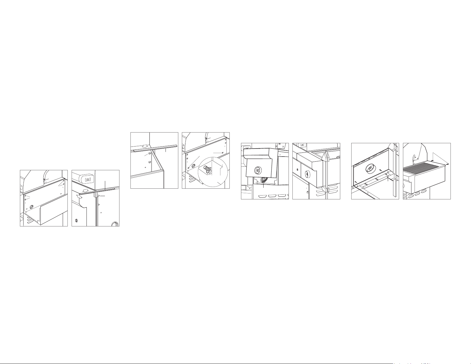
Side Burner Installation
INSTALL SIDE BURNER SHROUD
1 Side burner is placed inside shroud for shipping. Lift out
to remove side burner from shroud.
2 Hang shroud by hand-starting four 10-32 machine
screws provided through upper slots of shroud, into
upper holes of cart. Do not fully tighten screws until
shroud is properly aligned. Refer to the illustration below.
3 Place alignment tool provided with lip placed in the gap
between the grill and shroud as shown in the illustration
below.
4 To align front of shroud, push alignment tool back until
center block of tool is ush against front vertical ange
of shroud.
5 Align front of shroud (up and down) with alignment tool
until top of tool is ush with top surface of grill bullnose.
Align shroud (front to back) with tool until front of tool is
ush with front of bullnose. Tighten upper screw. Refer
to the illustration below.
SCREWS
SCREWS
ALIGNMENT
TOOL
SURFACES
FLUSH
UPPER
SCREW
Hang shroud. Align front of shroud.
6 To align back of shroud, place alignment tool at rear of
shroud. Align rear of shroud (up and down) with tool until
top of tool is ush with top surface of grill. Tighten upper
screw. Refer to the illustration below. Verify with align-
ment tool that front of shroud did not move, realign if
necessary.
7 Remove alignment tool and tighten two remaining
screws to slots just below the upper screws.
8 Install two
5
/16 x
3
/8 hex drive shoulder screws provided
into lower holes of shroud and through cart. Place two
1
/4–20 hex nuts from inside of cart and tighten. Refer to
the illustration below.
ALIGNMENT
TOOL
SURFACES
FLUSH
UPPER
SCREW
SHOULDER
SCREWS
HEX NUT
(INSIDE CART)
Align back of shroud. Secure shroud.
INSTALLATION
For natural gas installations, the gas line connection must
be made before installing the side burner.
INSTALL SIDE BURNER
1 Place side burner into shroud as shown in the illustration
below. Guide exible gas line and wire harness into cart
access hole. Verify alignment of unit prior to securing
side burner to shroud. If side burner does not align prop-
erly, remove, loosen screws and check shroud alignment
with tool. Reposition side burner until properly aligned.
2 Place a bar clamp with protected ends behind bullnose
on re box and under shroud. Do not include any part
of bullnose within bar clamp. Refer to the illustration
below.
3 Compress bar clamp until hole in bullnose aligns with
threaded hole in shroud. Alignment and placement of
this screw is very important to side burner alignment.
Refer to the illustration below.
4 Attach side burner to shroud by rst placing 8-32 hex
cap screw provided into right side of front underside of
bullnose and into shroud. Then, place left side hex cap
screw. Tighten screws and remove bar clamp.
5 At rear of unit, push side burner toward grill to establish
proper gap at rear. Loosen rear cart screws and shift
grill if necessary to achieve proper gap. Install two 8-18
pan head screws provided through shroud and into rear
of side burner as shown in the illustration below. Verify
proper alignment.
ACCESS HOLE
Position side burner. Position bar clamp.
HOLES
ALIGN
REAR
SCREWS
Hole alignment. Secure side burner.
Note - Cart and Side Burner not available in Australia - Built In models only
Loading ...
Loading ...
Loading ...