Loading ...
Loading ...
Loading ...
8
INSTALLATION
BRÛLEUR LATÉRAL BGC131/132 À CHARIOT MODÈLES CAD130
ÉTAPE 1
Retirez le couvercle, la grille et le ramasse-gouttes du brûleur latéral.
ÉTAPE 2
Fixez les deux prévues 10-24 x 1 vis à tête hexagonale pour les trous supérieurs du panneau latéral. Ne serrez pas
encore complètement elles. Laissez un «espace huitième sous la tête de boulon, comme illustré sur la figure.
ETAPE 3
Utilisez ces deux boulons pour fixer le brûleur latéral dans les trous de serrure comme indiqué sur la figure.
ADDENDUM – SIDE BURNER INSTALLATION
MODELS: BGB131/BGB132
This addendum supplements the Use and Care and Installation Guide (238044 Rev. B). If you
have a Cart Access Drawers (CAD-30) and wish to install the BGB131/132 on the cart, use the
following instructions and hardware as an addendum to page 5 and to replace pages 6 and 7.
Page 5:
Contents Qty. Part No.
2 211338
2 211328
Hex head bolt
10-24 x 1
Hex head bolt
1/4-20 x 3/4
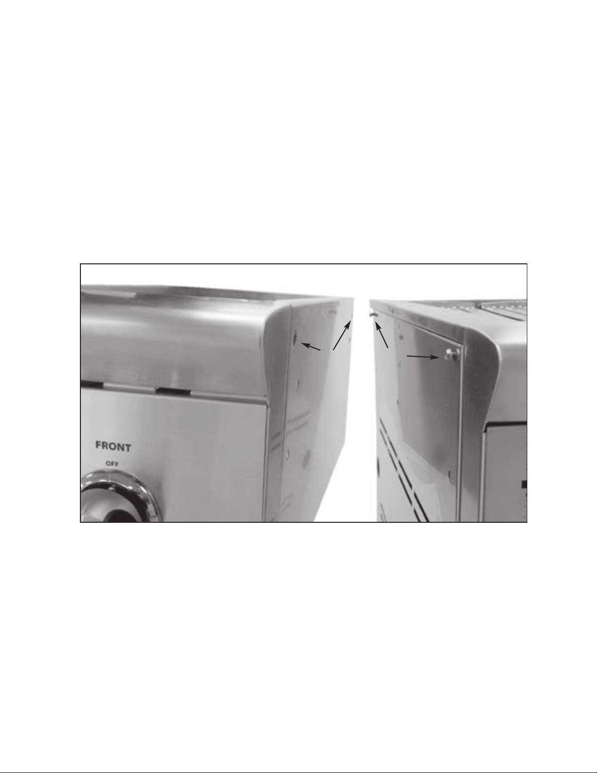
Fig.01
Keyholes
Bolts
(211338)
Tools Required
5/16 Wrench
7/16 Wrench
Pages 6 and 7:
STEP 1
Remove the cover, grate, and drip pan from the side burner.
STEP 2
Attach the two provided 10-24 x 1 hex head bolts (211338) to the upper holes of the side panel. Do
not completely tighten them yet. Leave an 1/8” space under the bolt head as shown on Fig. 01.
STEP 3
Use these two bolts to attach the side burner through the keyholes as shown on Fig. 01.
Continued on back
FIG. 03
Loading ...
Loading ...
Loading ...