Loading ...
Loading ...
Loading ...
13
INSTALLATION
GAS HOOKUP
LP TANK REQUIREMENTS
n
A dented or rusty LP gas cylinder may be hazardous and should be
checked by your LP supplier. Never use a cylinder with a damaged
valve.
n
The LP gas cylinder must be constructed and marked in
accordance with the specifications for LP gas cylinders of the U.S.
Department of Transportation (DOT) and designed for use with a
Type 1 system only.
n
Do not change the regulator/hose assembly from that
supplied with the unit or attempt to use a Type 1 equipped
regulator/hose assembly with a standard 510 POL tank/valve as-
sembly. The cylinder must be provided with a shut-off valve termi-
nating in an LP gas supply cylinder valve outlet specified, as
applicable, for connection Type 1.
n
If the appliance is stored indoors, the cylinder must be disconnect-
ed and removed from the appliance.
n
Cylinders must be stored outdoors in a well ventilated area out of the reach of children.
n
Gas cylinder supply must be turned off when not in use.
NATURAL GAS HOOKUP (continued)
To hook-up the fittings supplied with the side burner, assemble as shown in Fig.06. Use joint compound on
male threads only.
Do not use joint compound on the flare end of the 1/2” NPT to 3/8”
flare adapter. Ensure that the regulator arrow points in the direction of
gas flow-towards the unit, away from the supply.
Do not forget to place the installer-supplied gas valve in an accessible
location.
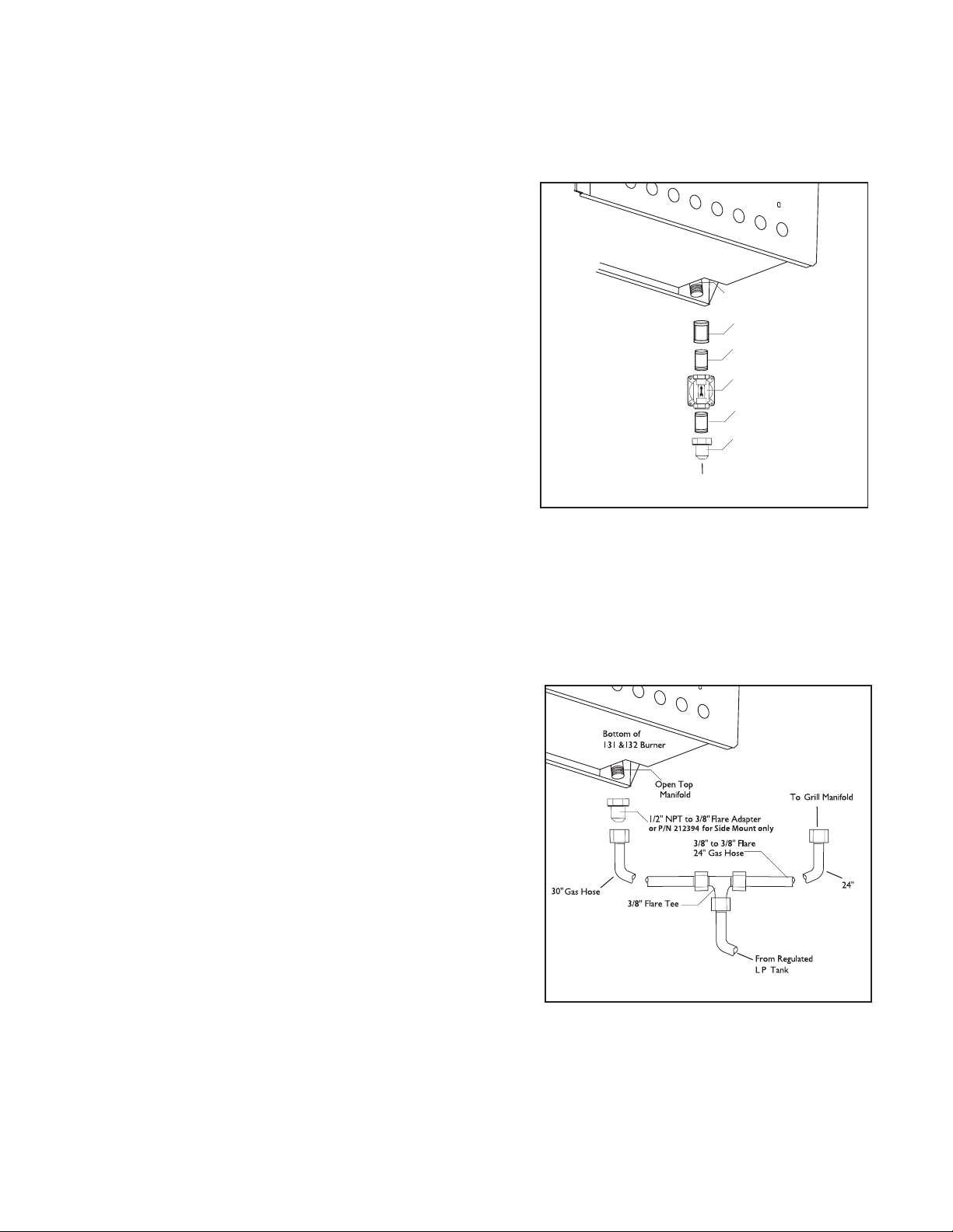
LP GAS HOOKUP
CONNECTION: 1/2” NPT female with 3/8” flare adapter
(included). Use 90º elbow 1/2” NPT with 3/8” flare
(P/N 212394) for side mount models only when installing on the cart.
Use sealer on 1/2” NPT threads only.
OPERATING PRESSURE: 11.0” W.C. side burner uses the LP regulator
from adjoining grill.
SUPPLY PRESSURE: 12” to 14” W.C.
Apply joint compound to the threaded end of the side burner gas
inlet and tighten the adapter to the pipe. Assemble the 24” and
30” hoses to the 3/8” flare tee, as shown in Fig.07. Tighten the regulator hose to the remaining fitting of the 3/8”
flare tee.
Open Top
Manifold
Bottom of
131 &132 Burner
1/2" Coupling
1/2" NPT x 2.0”
Nipple
1/2" NPT to 3/8"
Flare Adapter
Regulator
To Gas Supply
1/2" NPT x 2.0”
Nipple
FIG. 06 Natural Gas
FIG. 07 LP Gas
Loading ...
Loading ...
Loading ...