
XVM-F65WL 2-645-713-11(1)
XVM-F65WL 2-645-713-11(1)
XVM-F65WL 2-645-713-11(1)
XVM-F65WL 2-645-713-11(1)
Installation
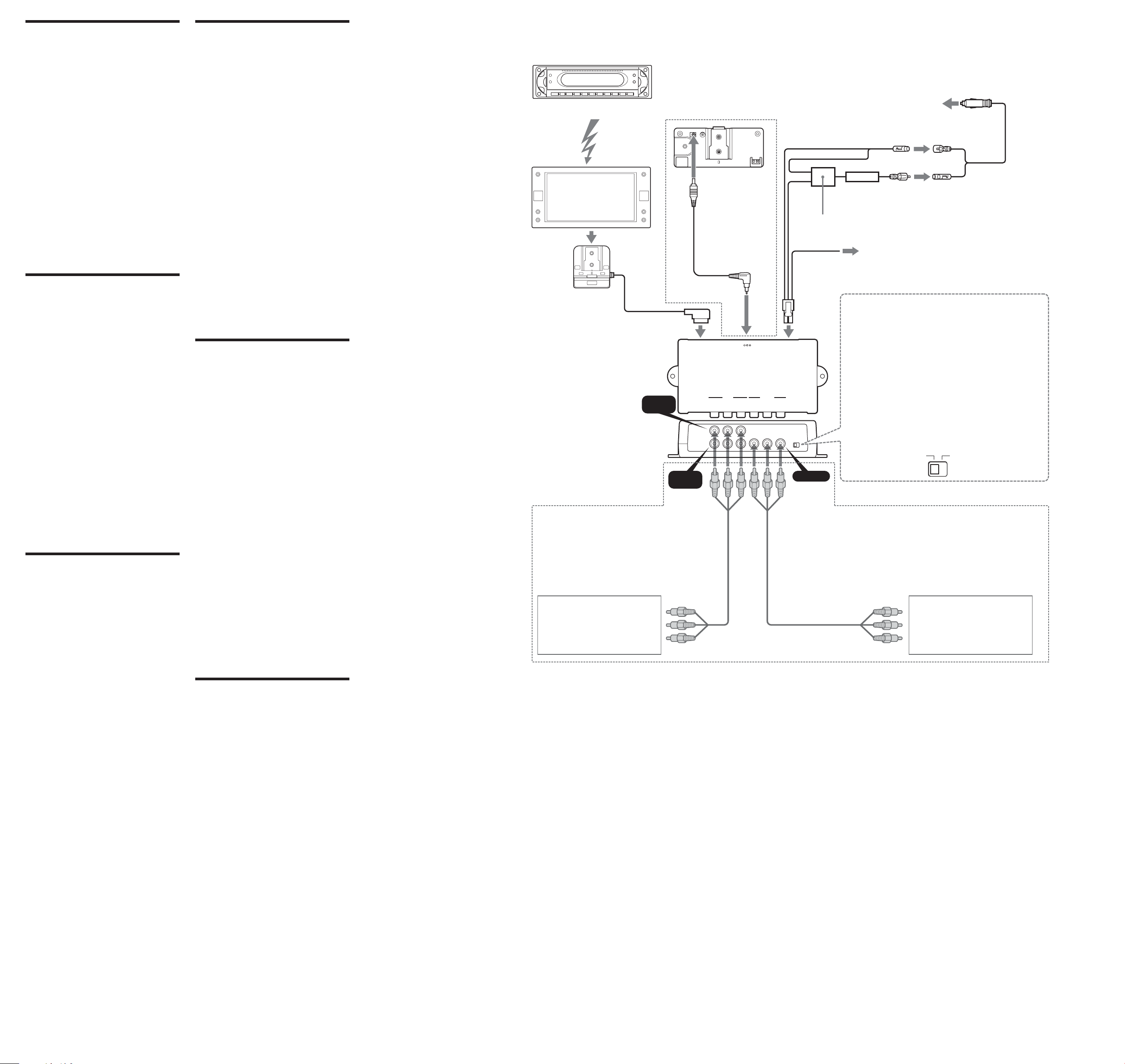
Installation diagram A
Refer to the installation diagram and ask a
qualified technician for the installation of the
unit.
Be sure to securely fasten all equipment to
the car chassis, etc., to prevent them from
moving while your car is in motion.
Note
All equipment other than one Mobile Monitor and
one Connection Box is optional.
Before installing the
monitor
• This monitor is designed for safe operation
during driving.
• Be sure to install the unit in a suitable position.
Improper installation can cause a serious
accident.
• Be sure not to install the unit where it will
interfere with the airbag system.
Caution on installation
Do not install the unit:
— in a hot place, subject to direct sunlight, near
a heater or in a car with the windows closed
(especially in summer) or in an extremely
cold place.
— in a place subject to excessive dust, moisture.
— in a place which could harm the passenger.
— in a place which could distract the driver.
— on a door or the ceiling.
Notes
• Clean the mounting surface well with the
cleaning cloth.
• When tightening the screws, make sure that the
nearby wiring does not get caught.
Installing the monitor
on the headrest B
The monitor can be installed behind the
headrest by using the supplied headrest
installation kit.
Seat types on which you can
mount the installation kit
•A seat with 2 headrest rods of diameter 10 mm
to 15 mm.
•A seat with rods spaced between 42 mm and
192 mm.
Note
Depending on the seat type, it may not be possible
to mount this unit.
C
1 Remove the headrest from the seat
by pressing the notch.
2 Adjust the rod spacing A and depth
positioning B of the installation kit
depending on your headrest.
Select either the 12 mm or 15 mm holes
depending on the diameter of the rod.
3 Insert the rods into the holes of the
installation kit and replace the
headrest to the seat. Tighten the
screws.
4 Loosen the knob C and adjust the
angle of the part that holds the
cradle.
Once adjusted, tighten the knob
firmly.
5 Install the cradle onto the
installation kit, and tighten the
screw on the bottom using things
like a coin.
6 Slide the monitor on the cradle until
you hear the click sound.
Note
The backside of the installation cradle 2 should be
pressed against the headrest for the stable
installation.
Removing the monitor
from the cradle D
Slide the monitor upwards while pressing the
button on the cradle.
Ø10 mm - 15 mm
B
A
A
6
C
12 mm
15 mm
Front
Avant
42 mm - 192 mm
Tweeter Left
Haut-parleur d’aiguës gauche
MEX-R5
Tweeter Right
Haut-parleur d’aiguës droit
Front Right speaker
Enceinte avant droite
Installation kit
Kit d’installation
Rear Right speaker
Enceinte arrière droite
Subwoofer
Haut-parleur d’extrême grave
2
4
6
Installation
Schéma d’installation
A
Consultez le schéma d’installation et demandez
à un technicien qualifié d’installer l’appareil.
Fixez fermement tous les équipements au
châssis de la voiture etc. pour éviter leur
déplacement quand la voiture roule.
Remarque
Tous les équipements autres qu’un moniteur
mobile et une boîte de raccordement sont en option.
Avant l’installation du
moniteur
• Ce moniteur est conçu pour un
fonctionnement sûr pendant la conduite.
• Installez-le à une position convenable. Une
installation incorrecte pourrait provoquer un
accident grave.
• Installez l’appareil à un emplacement où il ne
gênera pas l’airbag.
Précautions pour l’installation
N’installez pas l’appareil:
—À un emplacement chaud, en plein soleil,
près d’un chauffage ou dans une voiture à
fenêtres fermées (en particulier en été) ou à
un endroit extrêmement froid.
—À un endroit soumis à une poussière et/ou
humidité excessives
—À un endroit où il pourrait blesser le
passager.
—À un endroit où il pourrait distraire le
conducteur.
— Sur une portière ou au plafond.
Remarques
• Nettoyez bien la surface de montage avec le
chiffon de nettoyage.
• Au serrage des vis, vérifiez que le câblage à
proximité n’est pas coincé.
Installation du
moniteur sur l’appuie-
tête B
Le moniteur peut être installé derrière l’appuie-
tête en utilisant le kit d’installation d’appuie-tête
fourni.
Types de sièges sur lesquels le
kit d’installation peut se monter
• Un siège avec 2 tiges d’appuie-tête d’un
diamètre de 10 mm à 15 mm.
• Un siège avec tiges espacées de 42 mm à
192 mm.
Remarque
Le montage de l’appareil peut être impossible selon
le type de siège.
C
1 Retirez l’appuie-tête du siège en
appuyant sur l’encoche.
2 Ajustez l’espacement des tiges A et
le positionnement en profondeur B
du kit d’installation selon votre
appuie-tête.
Sélectionnez des trous de 12 mm ou 15 mm
selon le diamètre de la tige.
3 Insérez les tiges dans les trous du kit
d’installation et replacez l’appuie-
tête sur le siège. Serrez les vis.
4 Desserrez le bouton C et ajustez
l’angle de la partie tenant le berceau.
Après l’ajustement, serrez
fermement le bouton.
5 Installez le berceau sur le kit
d’installation, et serrez la vis à la
base avec une pièce de monnaie ou
similaire.
6 Glissez le moniteur sur le berceau
jusqu’au déclic de mise en place.
Remarque
L’arrière du berceau d’installation 2 doit être
pressé contre le repose-tête pour obtenir une
installation stable.
Retrait du moniteur du
berceau D
Glissez le moniteur vers le haut en appuyant sur
le bouton du berceau.
Notch
Encoche
Front
Avant
Mobile Monitor
Moniteur mobile
Front Left speaker
Enceinte avant gauche
Rear Left speaker
Enceinte arrière gauche
Cradle
Berceau
2
A
B
C
D
1
3
5
Headrest
Appuie-tête
Press to release.
Appuyez pour libérer.
Mobile Monitor
Installation/connections
Installation/connexions
2005 Sony Corporation Printed in Korea
XVM-F65WL
Parts list
Nomenclature
3
6
The numbers in the list are keyed to those in the instructions.
Les numéros sur la liste correspondent à ceux dans le manuel.
Die Nummern in der Liste entsprechen denen in der Anleitung.
2-645-713-11(1)
2
5
4
1
01GB+EUR.p65 05.6.3, 5:36 PM1
XVM-F65WL 2-645-713-11(1)
XVM-F65WL 2-645-713-11(1)
XVM-F65WL 2-645-713-11(1)
XVM-F65WL 2-645-713-11(1)
MONITOR
(XVM)
DC OUT 9V
MAX 1A
INPUT
VIDEO 1
VIDEO 2
RGB
LOCATION
REAR/FRONT
OUTPUT
VLRVLR
POWER
DC 12V 3A
REAR FRONT
INPUT
VIDEO 1
OUTPUTINPUT
VIDEO 2
3
2
5
1
4
Warning
Do not disassemble or remodel the unit.
This can cause electric shock, personal injury or
fire. Do not connect any other system’s power
supply cord to the unit’s power supply cord
directly. If you are in any doubt about the safe
installation of this unit, please consult your
nearest Sony dealer.
Do not damage any pipes, tubes, fuel
tank or electric wiring system when
installing this unit.
This can cause fire. Before drilling any holes in
car panels for the installation of this unit, make
sure the installation will not damage any hidden
car parts.
Do not use any nuts or bolts connected
to the steering linkage, fuel supply or
braking systems.
This can cause fire or loss of control of the car.
Do not mount the monitor where it will
interfere with the airbag system.
This may cause the airbag to malfunction and
injury to the passenger in case of a crash.
Caution
• This unit is designed for negative earth 12 V
DC operation only.
• Do not get the wires under a screw, or caught
in moving parts (e.g. seat railing).
• Before making connections, turn the car
ignition off to avoid short circuits.
• Connect the red power input leads only after
all other leads have been connected.
• Be sure to connect the red power input lead to
the positive 12 V power terminal which is
energized when the ignition key is in the
accessory position.
After installing and connecting the unit, tape the
cords to tie them up in a bundle so it will not
interfere with normal driving operations. Be
sure that the steering, shift lever and brake
pedal do not get tangled in the cords.
It is very dangerous for the cords to become
tangled with the gearshift lever during
driving.
Notes
• Secure the connecting cords away from the seat
adjustment rails and the door frame.
• Make sure all other electric devices such as brake
lights and headlights are working properly after
installation is completed. Also check that the
indicators turn on and the horn works properly.
Fuse replacement
If the fuse blows, check the power connection
and replace the fuse. If the fuse blows again after
replacement, there may be an internal
malfunction.
Warning
Use a fuse with the specified amperage rating.
Use of a higher amperage fuse may cause
serious damage to the unit.
Notes
• Be sure to connect the power input cord after all
other cords have been connected.
• Be sure to insert each connector securely, as
vibration through driving may cause a poor
connection.
• When removing the cable, hold the connector to
avoid damages.
Avertissement
Ne démontez et ne trafiquez pas
l’appareil.
Cela pourrait provoquer une décharge
électrique, des blessures ou un incendie. Ne
connectez aucun cordon d’alimentation d’un
autre système directement au cordon
d’alimentation de cet appareil. Si vous avez des
doutes sur la sécurité de l’installation de
l’appareil, consultez le revendeur Sony le plus
proche.
N’endommagez pas les tuyaux, les
flexibles, le réservoir à carburant ou le
câblage électrique à l’installation de cet
appareil.
Cela pourrait provoquer un incendie. Avant de
percer des trous dans les panneaux intérieurs de
la voiture pour installer cet appareil, assurez-
vous de n’endommager aucune pièce
automobile cachée.
N’utilisez pas les écrous ou boulons
connectés à la tringlerie de direction,
aux systèmes l’alimentation en
carburant ou de freinage.
Cela pourrait provoquer un incendie ou une
perte de contrôle de la voiture.
Ne montez pas le moniteur à un em-
placement où il interférera avec l’airbag.
Cela pourrait provoquer un dysfonctionnement
et blesser le passager en cas de collision.
Précautions
• Cet appareil est conçu seulement pour le
fonctionnement sur 12 V CC à masse négative.
• Prenez garde que les fils ne soient pas coincés
sous une vis, ou happés une pièce mobile (par
ex. rails de siège).
• Lors des connexions, coupez la clé d’allumage
de la voiture pour éviter tout court-circuit.
• Connectez le conducteur d’entrée
d’alimentation rouge seulement une fois que
tous les autres conducteurs ont été raccordés.
• Connectez bien le conducteur d’entrée
d’alimentation rouge à la borne d’alimentation
12 V positive excitée quand la clé d’allumage
est en position accessoire.
Après l’installation et le raccordement de
l’appareil, attachez les cordons avec du ruban
adhésif en faisceau pour qu’ils ne gênent pas les
opérations de conduite normales. Vérifiez que
les cordons ne sont pas emmêlés avec le levier
de commande, le levier de vitesse et la pédale de
frein.
Il est très dangereux que les cordons
s’emmêlent avec le levier de vitesses pendant
la conduite.
Remarques
• Immobilisez les cordons de raccordement loin
des rails d’ajustement du siège et du cadre de
portière.
• Vérifiez que tous les autres dispositifs électriques
comme les feux de freinage et les phares
fonctionnent correctement après la fin de
l’installation. Vérifiez aussi que les indicateurs
s’allument et que le klaxon fonctionne
correctement.
Remplacement du
fusible
Si le fusible saute, vérifiez la connexion
d’alimentation et remplacez le fusible. Si le
fusible saute à nouveau, un dysfonctionnement
interne est possible.
Avertissement
Utilisez un fusible de l’ampérage spécifié.
L’emploi d’un fusible à ampérage plus élevé
peut sérieusement endommager l’appareil.
Remarques
• Connectez bien le cordon d’entrée d’alimentation
après le raccordement de tous les autres cordons.
• Insérez fermement tous les connecteurs, car la
vibration due à la conduite peut provoquer une
mauvaise connexion.
• Au retrait du câble, saisissez le connecteur pour
éviter les dommages.
Connections
Connexions
Fuse (4 A)
Fusible (4 A)
Red
Rouge
Black
Noir
Blue
Bleu
Cigar lighter adaptor (supplied)
Adaptateur d’allume-cigare (fourni)
To the cigar lighter socket
A la douille d’allume-cigare
To the parking brake switch cord
Au cordon du commutateur du frein de stationnement
Switch the location you mount the monitor
To use the monitor on dashboard:
Switch to “FRONT” and connect the blue cord to the parking
brake.
To use the monitor behind the headrest:
Switch to “REAR”.
Commutez l’emplacement de montage du moniteur
Pour utiliser le moniteur sur le tableau de bord:
Commutez à « FRONT » et connectez le cordon bleu au frein de
stationnement.
Pour utiliser le moniteur derrière le repose-tête:
Commutez à « REAR ».
RCA cable (not supplied)
Câble RCA (non fourni)
RCA cable (not supplied)
Câble RCA (non fourni)
From DVD player
Du lecteur DVD
Installation cradle
Berceau d’installation
LC filter
Filtre LC
XVM-F65WL
MV-100BAT
(optional)
MV-100BAT
(en option)
To charge the
rechargeable battery
Pour charger la pile
rechargeable
MEX-R5 (optional)
MEX-R5 (en option)
Battery
rechargeable
cable (Supplied)
Câble de pile
rechargeable
(en option)
To other monitor
A un autre moniteur
01GB+EUR.p65 05.6.3, 5:36 PM2