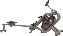
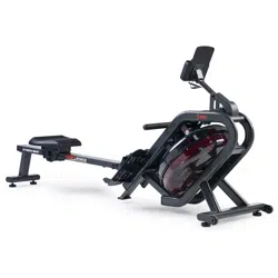
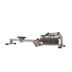
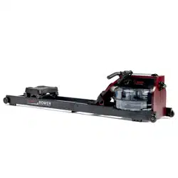
We value your experience using Sunny Health and Fitness products. For assistance with parts or troubleshooting, please contact us at [email protected] or 1-877-90SUNNY (877-907-8669).
STEP 1:
Remove the pre-assembled Limit Cushion (No. 12) and 2 Screws (No. 13) from the Slide Rail (No. 3) using Spanner (No. 99).
Slide the Seat (No. 30) to the Slide Rail (No. 3), make sure Seat (No. 30) through the position of Limit Cushion (No. 12). Then attach the Limit Cushion (No. 12) to the Slide Rail (No. 3) with 2 Screws (No. 13) that were just removed by using Spanner (No. 99).
Attach the Rear Support Tube (No. 4) to the Slide Rail (No. 3) with 4 Screws (No. 19) and 4 Flat Washers (No. 17) using Allen Wrench (No. 100)
STEP 2:
2-1: Attach the Slide Rail (No. 3) to the Main Frame (No. 1) with the 2 Bolts (No. 5 & 10) by using Allen Wrench (No. 101 & 100). Then tighten with Knob (No. 36) and Flat Washer (No. 37), and finally insert Spring Knob (No. 34).
2-2: Connect the 2 Sensor Wires (No. 40) with 2 Extension Wire (No. 29).
2-3: After connecting the 2 Sensor Wires (No. 40) with 2 Extension Wire (No. 29). The wires will be exposed. (Fig A)
2-4: Move all wires to the side of the plate A. (Fig B)
2-5: Attach the Protective Cover (No. 88) and Fixed Plate (No. 89) to the Main Frame (No. 1) with 4 Screws (No. 19) and 4 Flat Washers (No. 17) using Allen Wrench (No. 100).
Note: Do not cut any wires when attaching the Protective Cover (No. 88) and Fixed Plate (No. 89) to the Main Frame (No. 1).
STEP 3:
3-1: Remove the pre-assembled 2 Screws (No. 43) from the Main Frame (No. 1) using Spanner (No. 99). Attach the Bottle Holder (No. 44) to the Main Frame (No. 1) with 2 Screws (No. 43) that were just removed by using Spanner (No. 99).
3-2: Remove the pre-assembled 6 Screws (No. 41) from the back Meter (No. 39) using Spanner (No. 99).
3-3: Insert the Tablet Holder (No. 45) to the Meter (No. 39) with 2 Screws (No. 41) that were just removed by using Spanner (No. 99).
3-4: Connect 2 Extension Wires (No. 29) with wires of Meter (No. 39). Then attach the Meter (No. 39) to the Meter Plate (No. 7) with 4 Screws (No. 41) that were just removed by using Spanner (No. 99).
3-5: After attaching the Meter (No. 39) to the Meter Support Tube (No. 2). The 2 Extension Wires (No. 29) and wires of Meter (No. 39) will be exposed. (Fig A)
3-6: Push all wires into the upper Meter Support Tube (No. 2). The wires will be exposed out of hole A from the bottom Meter Support Tube (No. 2). Push all wires up into the Meter Support Tube (No. 2). (Fig B)
Note: Put all wires to the meter tube before attaching the Meter (No. 39) to Main Frame (No. 1).
The assembly is complete!
HOW TO FILL AND EMPTY THE TANK
Remove the Plug (No. 72) from the Upper Tank Cover (No. 73a).
To fill the tank with water, refer to Fig. A. Insert the Funnel (No. 11) into the tank, then use a cup or a bucket and Pumping Siphon (No. 42) to fill the tank. Use the water level gauge on the side of the tank to measure desired water level in the tank.
To empty the tank, refer to Fig. B. Place a bucket next to the rower and use the Pumping Siphon (No. 42) to pump out the water from the tank into the bucket.
Insert the Plug (No. 72) back into the Upper Tank Cover (No. 73a). Wipe off excess water around the area
NOTE:
Fill the tank only with tap water. Add 1 water purification tablet (1 packet is included). Never use pool chlorine or chlorine bleach. This will damage the tank and void the warranty.
Add a water purification tablet every 6 months or as needed. If water remains cloudy, replace the water in the tank.
Do not consume the tank water. Dispose the water after pumping it out from the tank.
WATER LEVEL
The water level gauge is on the side of the tank. There is a max level. Never fill over this limit. Filling the tank over this limit will void the warranty.
The resistance depends on the water level in the tank. The min level is the lowest resistance. The max level is the highest resistance.
BATTERY INSTALLATION & REPLACEMENT
BATTERY INSTALLATION:
Take out 2 AA batteries from meter box.
Press the buckle of battery cover on the back of the Meter (No. 39), then remove battery cover.
Install 2 AA batteries into the battery case on the back of the Meter (No. 39). Pay attention to the battery + and – poles before installing.
Press the buckle of battery cover, then put the battery cover back to the back of the Meter (No. 39).
The installation is complete!
BATTERY REPLACEMENT:
Press the buckle of battery cover on the back of the Meter (No. 39), then remove battery cover.
Remove the 2 old AA batteries in the battery case and install 2 new AA batteries into the battery case on the back of the Meter (No. 39). Pay attention to the battery + and – poles before installing.
Press the buckle of battery cover, then put the battery cover back to the back of the Meter (No. 39).
The replacement is complete!
NOTE: Always change both batteries at the same time. Do not mix battery types and do not mix old and new batteries. Dispose batteries according to your state and regional guidelines.
ADJUSTMENTS GUIDE
ADJUSTING THE BALANCE
Adjust the Hex Nuts (No. 32) on the Adjustable Foot Pads (No. 33) of the rower using Spanner (No. 99) if the rower is unbalanced during use.
CAUTION! Moving parts, such as the Seat (No. 30), can crush and cut. Keep hands clear of the Slide Rail (No. 3) during use!
MOVING THE ROWER
To move the rower, lift up the Rear Support Tube (No. 4) until the Rollers (No. 85) touch the ground. With the Rollers (No. 85) on the ground, you can transport the rower to the desired location with ease.
STORAGE
When not in use, you can save space by storing the rower vertically. Unscrew the Knob (No. 36) and Flat Washer (No. 37), and remove the Spring Knob (No. 34). (Fig B) Lower the Seat (No. 30) all the way down. Then fold the Slide Rail (No. 3) up. CAUTION: The Seat (No. 30) will slide down when folding the Slide Rail (No. 3).
Insert Knob (No. 36) and Flat Washer (No. 37) into the holes in the back of the Slide Rail (No. 3) and tighten. Then insert Spring Knob(No. 34). (Fig A) If not using the rower for more than a month, empty the tank before storing.
PEDAL ADJUSTMENT
The pedal strap is adjustable and can be personalized to fit the user’s foot size.
EXERCISE METER
Our computerized exercise meter on the Sunny Water Rowing Machine allows the user to tailor a personalized workout by monitoring their progress. During a workout, the exercise meter will alternately and repeatedly display the Time, Time/500M, SPM, Distance, Strokes, Total Strokes, Calories Burned, and Pulse.
BUTTONS
UP▲/DOWN ▼: Press these two buttons to scroll through the available selection. To adjust the function values upward and downward.
ENTER: To confirm your selection. During training, press this button to scan each display function.
START /STOP: To start and stop your selected workout program.
RESET: To return the meter back to the main menu. Press and hold for 3 seconds to reset values.
RECOVERY: To activate the RECOVERY PROGRAM that will automatically evaluate your fitness immediately after workout.
FUNCTIONS
TIME: Set target time (1 min ~ 99 min) by pressing UP and DOWN buttons, in 1 minute increments.
TIME/500M: Your average 500M time is automatically displayed.
SPM: Strokes per minute.
DISTANCE: Preset target distance (100 ~ 99900 meters) by pressing UP and DOWN buttons, in 100 meters increments.
STROKES: Set target stroke (10 ~ 9990 strokes) by pressing UP and DOWN buttons, in 10 strokes increments.
TOTAL STROKES: Accumulates total strokes from 0 to 9999.
CALORIES: Set target calories (10 ~ 9990 Cal) by pressing UP or DOWN buttons, in 10 Cal increments.
HRC/PULSE: Displays heart rate. In Manual Mode, set target pulse by pressing UP and DOWN buttons (30 ~ 240), in 1 BPM increments. HRC will display at the top of the meter. The meter will display your heart rate during training. When it reaches the target value, PULSE will flash, and the meter will beep until it is changed to another mode or you remove the chest strap. Pulse measurement function only works with 5.3 KHz chest strap heart rate monitors.
CALENDAR: The meter will display year, month, and day when meter is in sleep mode.
TEMPERATURE: The meter will display current room temperature when the meter is in sleep mode.
CLOCK: The meter will display current time when the meter is in sleep mode.
Note: Chest Strap Heart Rate Monitor is not included.
OPERATION
1. Install 2 PCS AA batteries (included) and meter will beep for 2 seconds (Fig.1). Then, the meter enters into the CLOCK & CALENDAR MODE (Fig.2).
2. The CLOCK will flash. Press UP button to set the hour. Press ENTER to confirm.
Press UP to set the minutes. Press ENTER to confirm. Continue press UP button to set the YEAR (in the STROKES window); MONTH (in the CALORIES window); DAY (in the PULSE window). Press ENTER to confirm when it is set.
After you confirm it, the ALARM will beep. Press ENTER to skip setting up the alarm. To set up the alarm, press UP button to turn on ALARM. An arrow will appear next to ALARM. Press ENTER. CLOCK window will flash. Press UP or DOWN buttons to set the alarm time. Press ENTER to confirm. Meter will go into the SPORT screen (Fig.3).
3. When you enter the SPORT screen, MANUAL and RACE will flash. Press UP or DOWN to select MANUAL or RACE. Press ENTER to confirm your selection.
(1) MANUAL (Fig.4): There are 2 options in MANUAL mode.
a. The meter can be set to countdown. When you select MANUAL, the value of TIME will start to flash. Press UP to set the value of TIME to countdown. Press ENTER to confirm it. Press ENTER to skip setting up the time COUNTDOWN and go to the next function. You can set the values for DISTANCE, STROKES, CALORIES, or PULSE. (Note: You can only set the value for one function to countdown. For example, if you have set the target value for TIME, then DISTANCE can’t be set.)
Press START button to start and the STOP icon will disappear. When the countdown reaches zero or you press STOP button, the meter will stop and display the average value.
b. The meter counts the value of your workout. Press START to start.
(2) RACE (Fig.5): Select RACE mode and L9 will flash. The TIME/500M will display 4:00. Then, press UP or DOWN to select L1 ~ L15. Press ENTER to confirm. Then, you can set the distance of the race (500 ~ 10000M) while the value of DISTANCE is blinking. Press ENTER, and the picture of the race will display on the screen.
The TIME/500M of the programs are as follows:
a. Press START button to start and STOP icon will disappear. USER and PC will display in the matrix (Fig.6). The meter will stop when either the user or meter has reached the race distance that was set. Then, the matrix displays “PC WIN” or “USER WIN” (Fig.7).
b. When the race is over, you can press START to start a race once again. Press RESET to leave the RACE screen.
(3) RECOVERY: This meter works with a 5.3 KHz chest strap heart rate monitor (not included). After exercising for a period of time, keep wearing the chest strap monitor and press RECOVERY button. All function displays will stop except “TIME” starts counting down from 00:60 to 00:00. Screen will display your heart rate recovery status with the F1, F2….to F6. F1 is outstanding. F6 is poor. User may keep exercising to improve the heart rate recovery status. (Press the RECOVERY button again to return the main display.)
ALARM: Alarm only works while the meter is in sleep mode. Alarm will not sound during exercise. Press and hold RESET to go to clock screen to set up ALARM.
SLEEP MODE: The meter will go into sleep mode after about 4 minutes of inactivity.
BATTERY: This meter uses 2 AA batteries, which are included. Changing the batteries will reset all values. If there is a problem with the display, try to change the batteries first. When changing the batteries, change both. Do not mix battery types. Do not mix old and new batteries. Dispose of old batteries according to your regional guidelines.