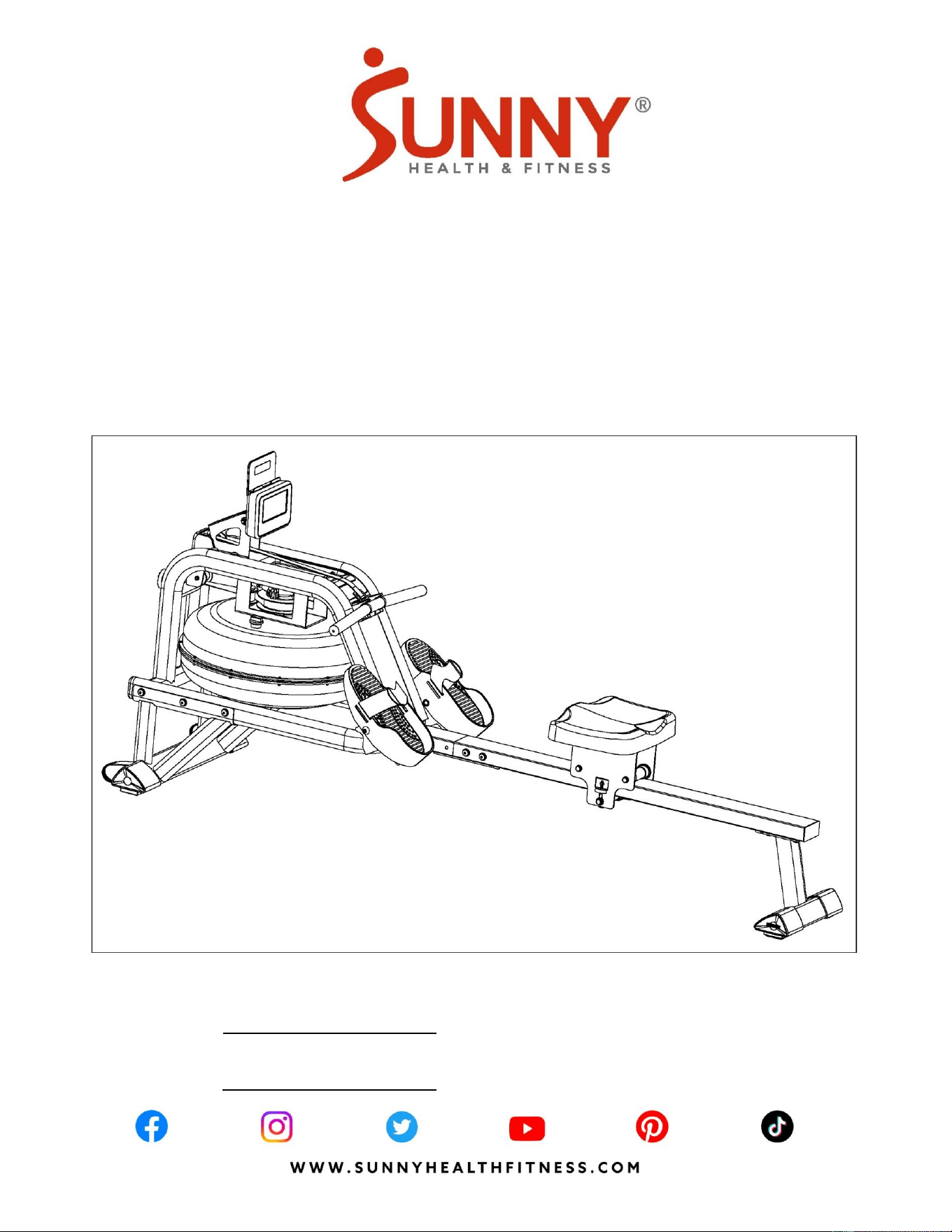
SMART OBSIDIAN SURGE 500 METER
WATER ROWING MACHINE
SF-RW5713 SMART
USER MANUAL
English, Pages 1~13 IMPORTANT! Please retain owner’s manual for maintenance and adjustment instructions. Your satisfaction
is very important to us, PLEASE DO NOT RETURN UNTIL YOU HAVE CONTACTED US:
support@sunnyhealthfitness.com or 1-877-90SUNNY (877-907-8669).
Español, Páginas 14~27 ¡IMPORTANTE! Conserve el manual del propietario para las instrucciones de mantenimiento y ajuste. Su
satisfacción es muy importante para nosotros, NO DEVUELVA HASTA HABERNOS CONTACTADO:
support@sunnyhealthfitness.com ó 1-877-90SUNNY (877-907-8669).

1
IMPORTANT SAFETY INFORMATION
We thank you for choosing our product. To ensure your safety and health, please use this
equipment correctly. It is important to read this entire manual before assembling and using the
equipment. Safe and effective use can only be achieved if the equipment is assembled, maintained,
and used properly. It is your responsibility to ensure that all users of the equipment are informed of
all warnings and precautions.
1. Before starting any exercise program, you should consult your physician to determine if you
have any medical or physical conditions that could put your health and safety at risk or prevent
you from using the equipment properly.Your physician’s advice is essential if you are taking
medication that affects your heart rate, blood pressure, or cholesterol level.
2. Be aware of your body’s signals. Incorrect or excessive exercise can damage your health. Stop
exercising if you experience any of the following symptoms: pain, tightness in your chest,
irregular heartbeat, shortness of breath, lightheadedness, dizziness, or feelings of nausea. If
you do experience any of these conditions, you should consult your physician before continuing
with your exercise program.
3. Keep children and pets away from the equipment. The equipment is designed for adult use
only.
4. Use the equipment on a solid, flat level surface with a protective cover for your floor or carpet.
To ensure safety, the equipment should have at least 2 feet (60 cm) of free space all around it.
5. Ensure that all nuts and bolts are securely tightened before using the equipment. The safety of
the equipment can only be maintained if it is regularly examined for damage and/or wear and
tear.
6. Always use the equipment as indicated. If you find any defective components while assembling
or checking the equipment, or if you hear any unusual noises coming from the equipment
during exercise, discontinue use of the equipment immediately and do not use until the problem
has been rectified.
7. Wear suitable clothing while using the equipment. Avoid wearing loose clothing that may
become entangled in the equipment.
8. Do not place fingers or objects into the moving parts of the equipment.
9. The maximum weight capacity of this unit is 300lbs (135kgs).
10. This equipment is not suitable for therapeutic use.
11. To avoid bodily injury and/or damage to the product or property, proper lifting and moving are
required.
12. Your product is intended for use in cool and dry conditions. You should avoid storage in
extreme cold, hot or damp areas as this may lead to corrosion and other related problems.
13. This equipment is designed for indoor and home use only; it is not intended for commercial use.
2
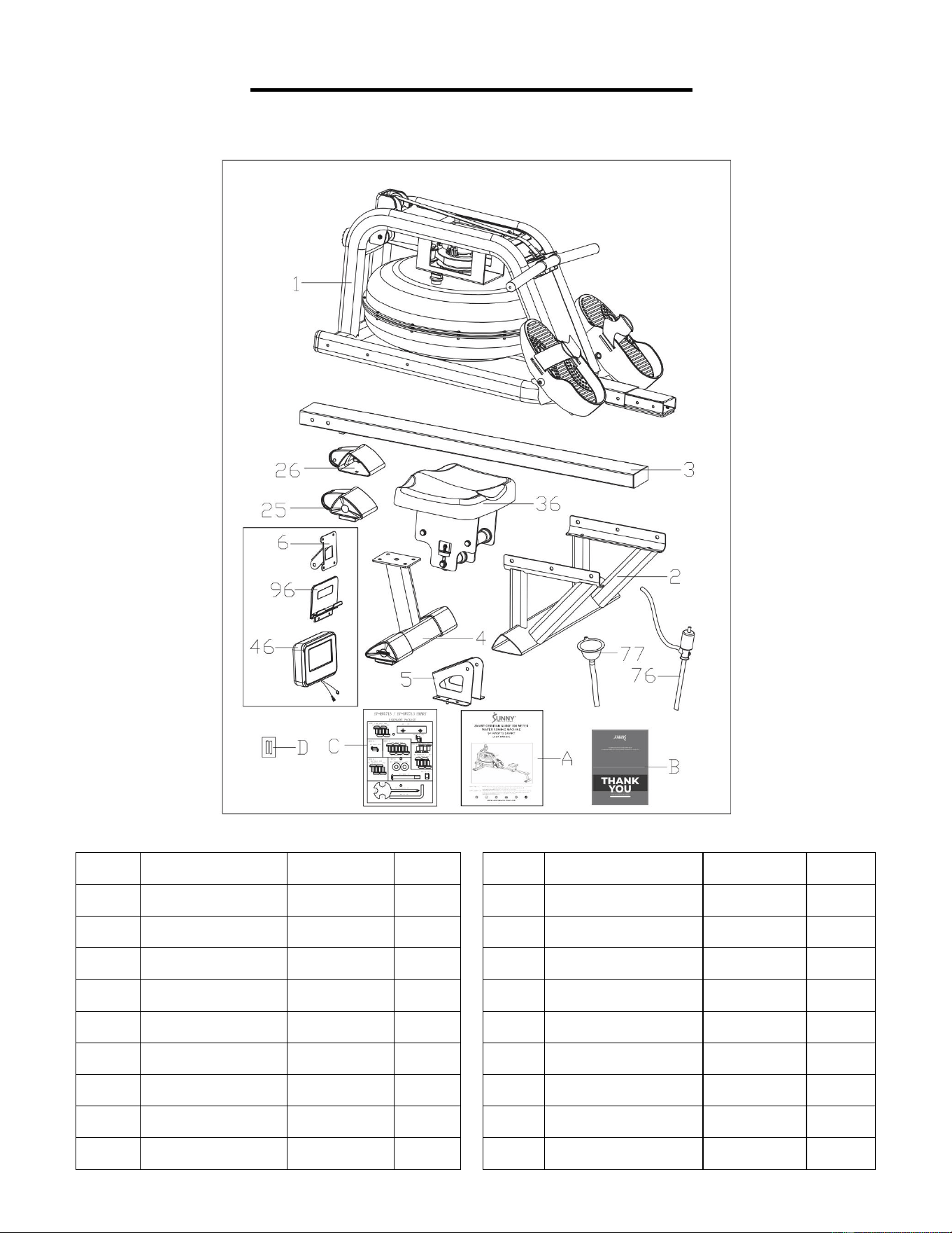
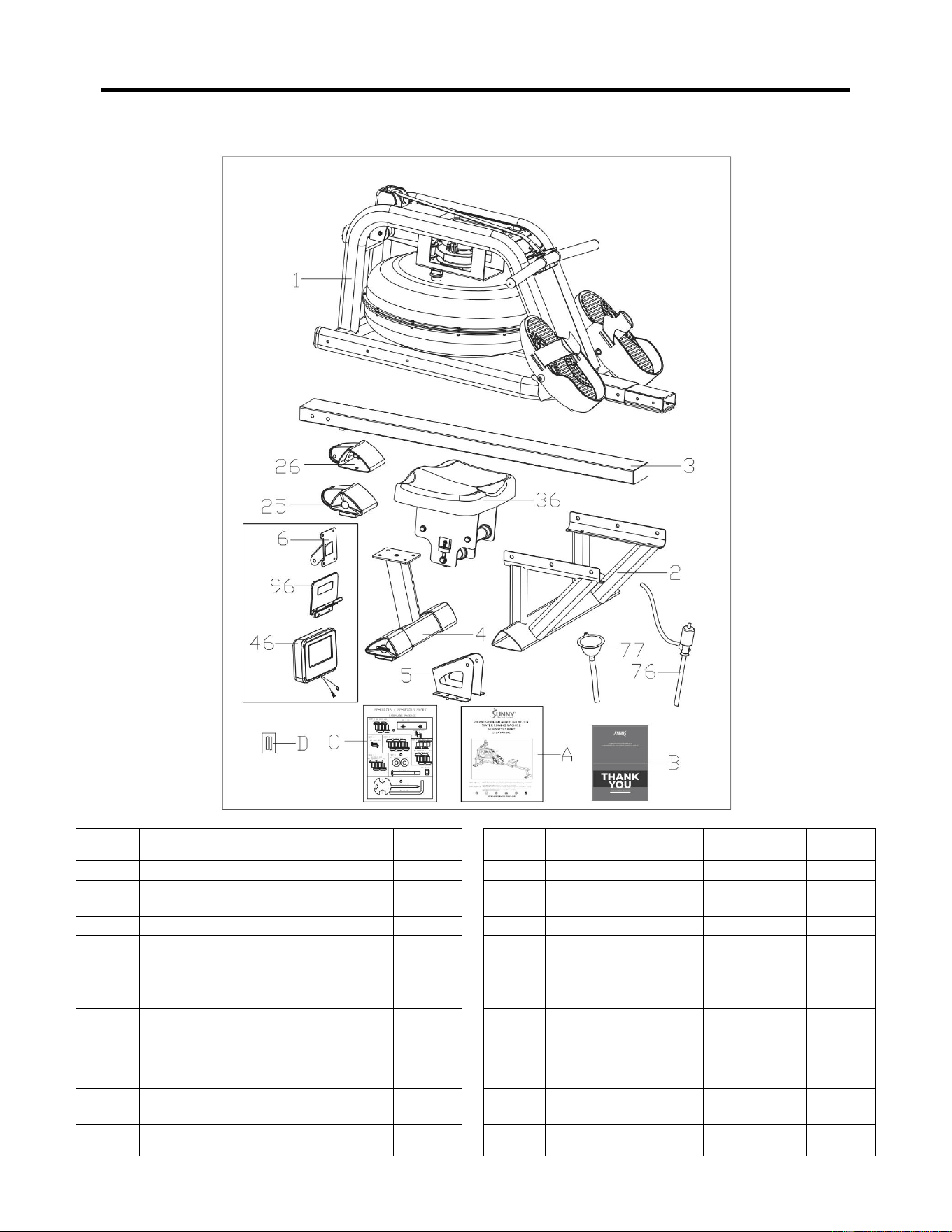
PRE-ASSEMBLY CHECK LIST
Before you start to assemble, please make sure all parts are included.
No.
Description
Spec.
Qty.
No.
Description
Spec.
Qty.
1
Main Frame
1
46
Meter
X-6422
1
2
Front Stabilizer
1
76
Pumping Siphon
1
3
Slide Rail
1
77
Funnel
1
4
Rear Stabilizer
1
96
Tablet Holder
1
5
Sensor Stand
1
A
Manual
1
6
Support Plate
1
B
Thank You Card
1
25
Left End Cap
1
C
Hardware Package
1
26
Right End Cap
1
D
Battery
AA
2
36
Seat
PU, Black
1
3
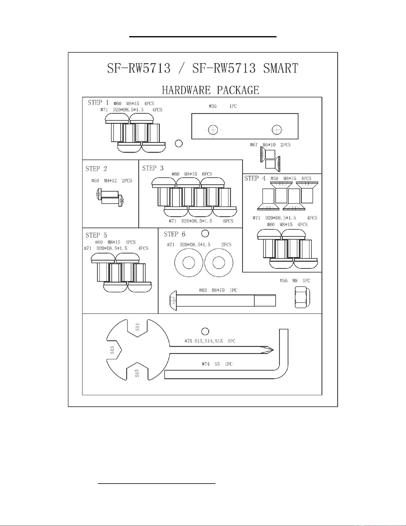
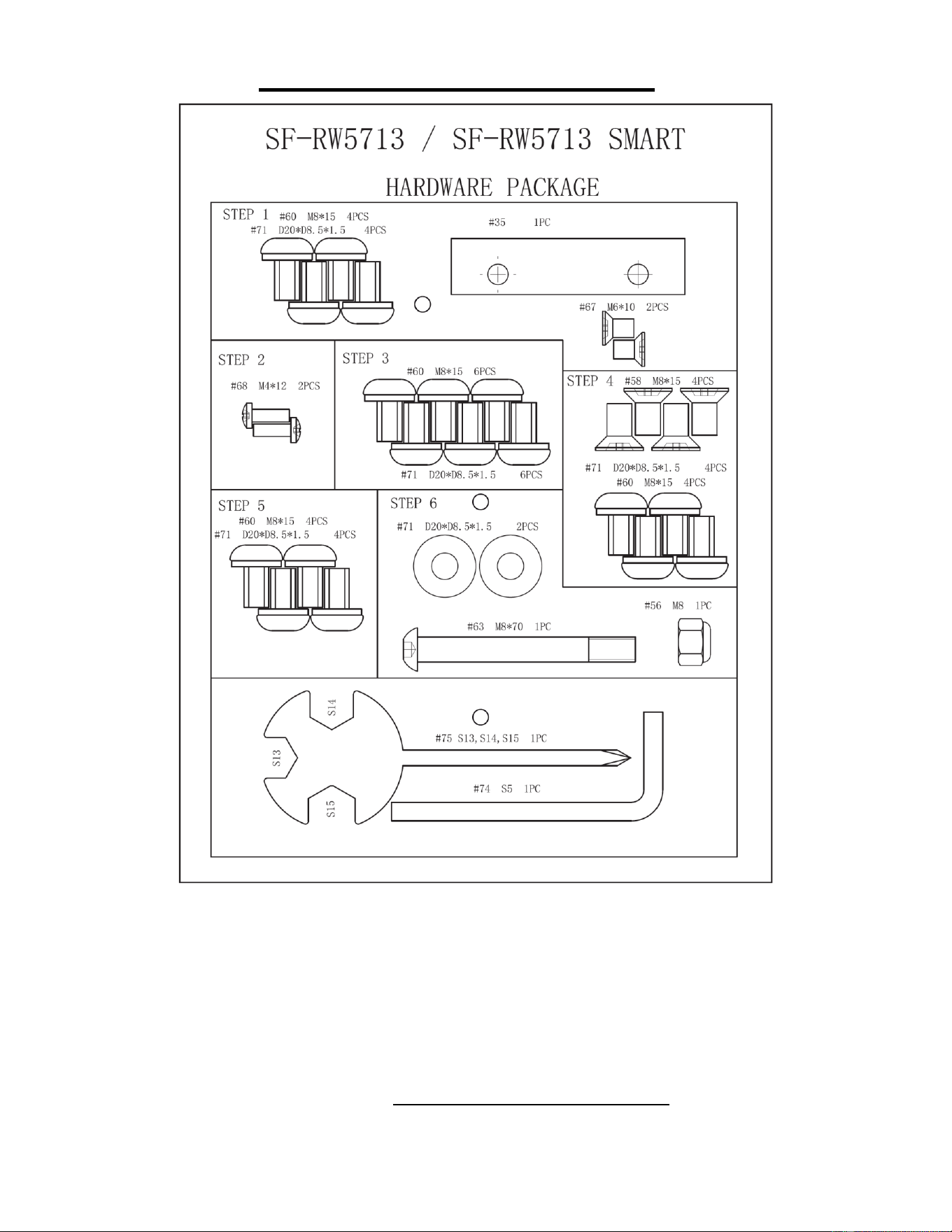
HARDWARE PACKAGE
Ordering Replacement Parts (U.S. and Canadian Customers only)
Please provide the following information in order for us to accurately identify the part(s) needed:
✓ The model number (found on cover of manual)
✓ The product name (found on cover of manual)
✓ The part number found on the “EXPLODED DIAGRAM” (pages 28~29) and “PARTS LIST”
(page 13)
4
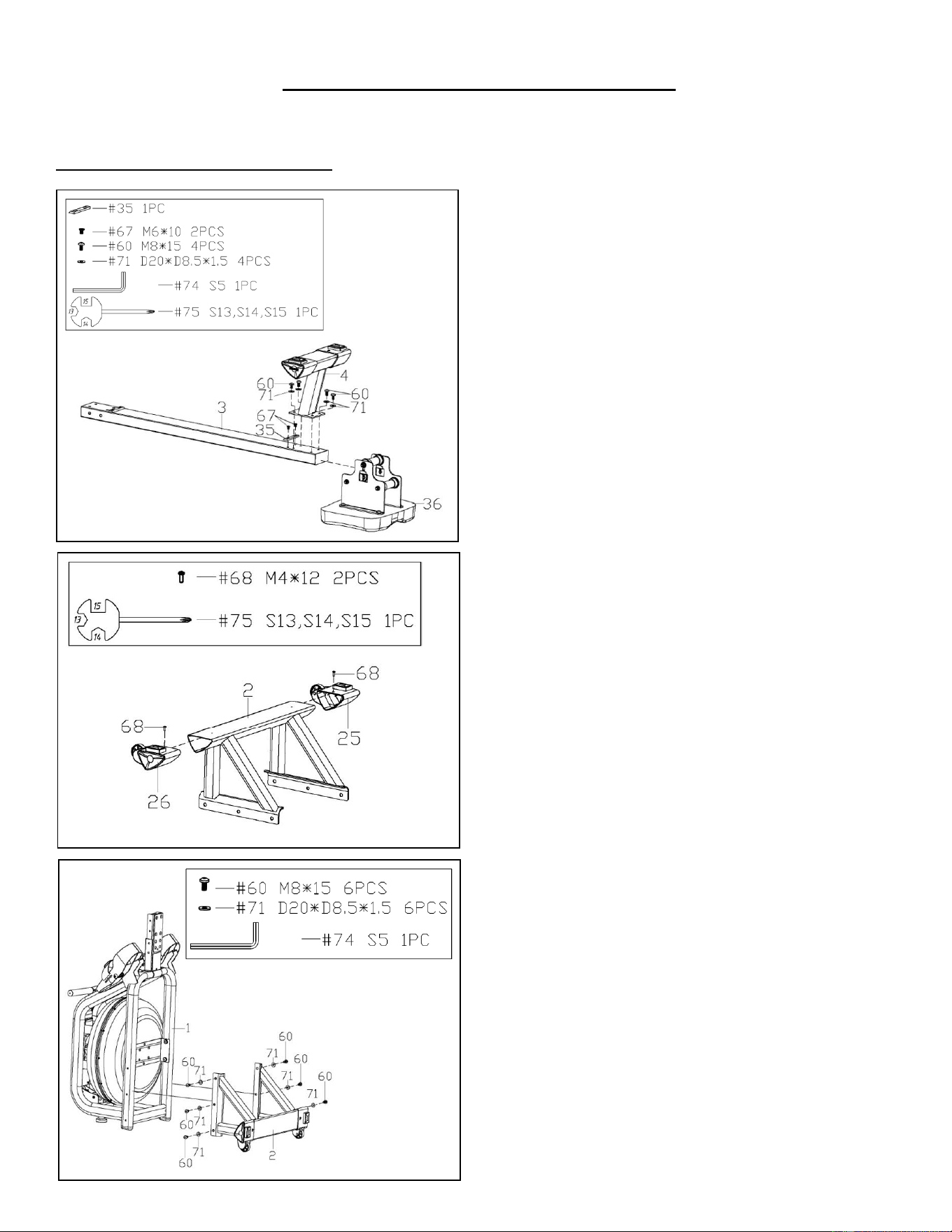
ASSEMBLY INSTRUCTIONS
We value your experience using Sunny Health and Fitness products. For assistance with parts or
troubleshooting, please contact us at [email protected] or 1-877-90SUNNY (877-
907-8669).
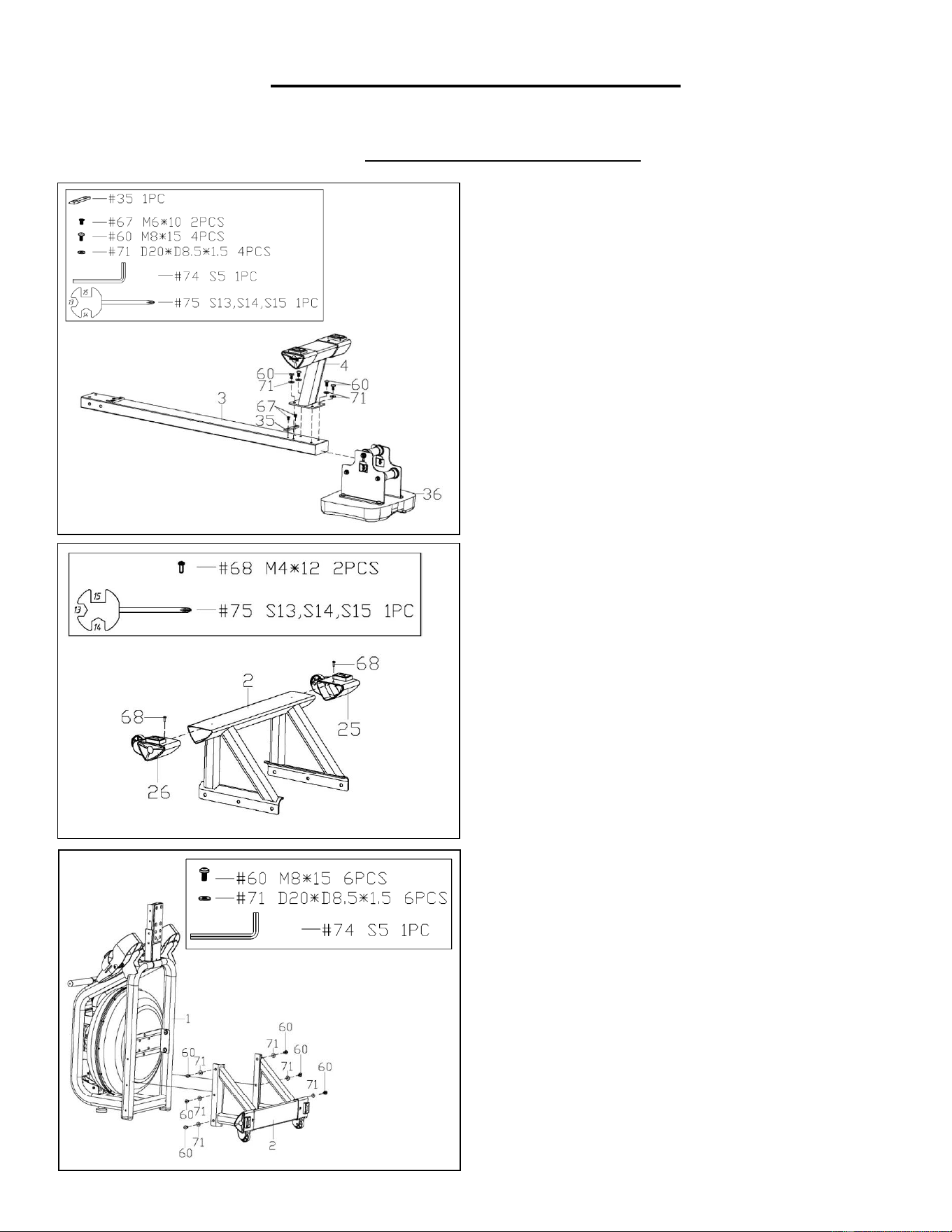
STEP 1:
NOTE: We recommend having 2 people to
assemble the product.
Turn over the Slide Rail (No. 3) and Seat (No.
36).
Slide the Seat (No. 36) onto the Slide Rail
(No. 3). Secure the Stopper (No. 35) with 2
Flat Cross Screws (No. 67). Tighten with
Spanner (No. 75). Then, attach the Rear
Stabilizer (No. 4) to the Slide Rail (No. 3) with
4 Washers (No. 71) and 4 Screws (No. 60).
Tighten with Allen Wrench (No. 74).
STEP 2:
Attach Left & Right End Caps (No. 25 & No.
26) to Front Stabilizer (No. 2). Then, tighten
with 2 Cross Screws (No. 68) using Spanner
(No. 75).
STEP 3:
Keep the Main Frame (No. 1) upright. Attach
Front Stabilizer (No. 2) to Main Frame (No. 1)
using 6 Washers (No. 71) and 6 Screws (No.
60). Insert all the 6 Screws (No. 60) partially
into the holes first, and then tighten with Allen
Wrench (No. 74).
5
We value your experience using Sunny Health and Fitness products. For assistance with parts or
troubleshooting, please contact us at [email protected] or 1-877-90SUNNY (877-
907-8669).
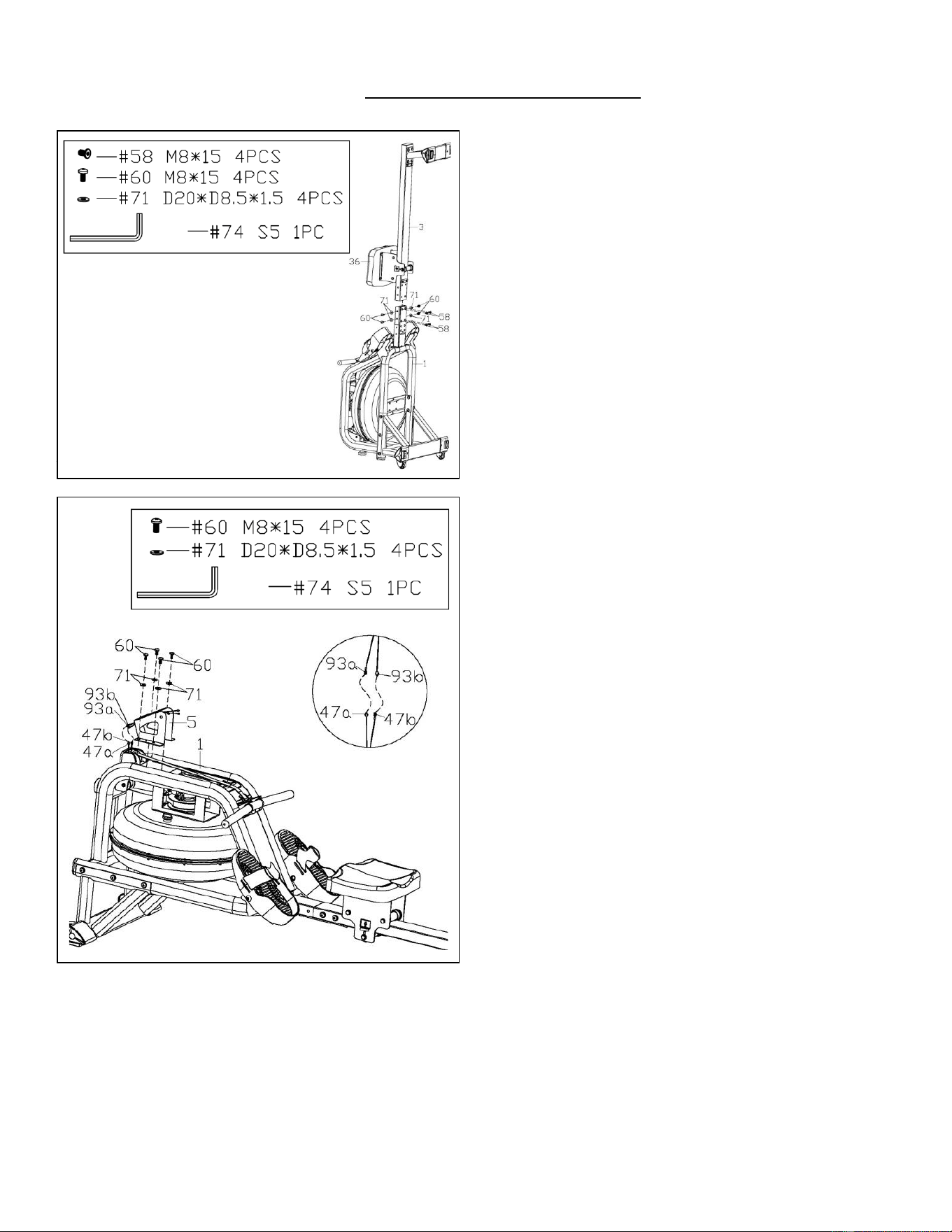
STEP 4:
NOTE: Move the Seat (No. 36) to the front of
the Slide Rail (No. 3) before assembly to
prevent it from gliding down during assembly.
Attach the Slide Rail (No. 3) to the Main
Frame (No. 1) using 4 Washers (No. 71), 4
Screws (No. 60), and 4 Flat Screws (No. 58).
Insert all 8 screws partially into the holes first,
and then tighten with Allen Wrench (No. 74).
STEP 5:
Connect the Inductor Wire A (No. 47a) to the
Sensor Wire A (No. 93a), connect the
Inductor Wire B (No. 47b) to the Sensor Wire
B (No. 93b).
Attach Sensor Stand (No. 5) to Main Frame
(No. 1) using 4 Washers (No. 71) and 4
Screws (No. 60). Tighten with Allen Wrench
(No. 74).
If you are sitting on the seat, the arrow sticker
on the Sensor Stand (No. 5) must be pointing
towards you. That means the Sensor Stand
(No. 5) is installed in the correct direction.

6
We value your experience using Sunny Health and Fitness products. For assistance with parts or
troubleshooting, please contact us at [email protected] or 1-877-90SUNNY (877-
907-8669).
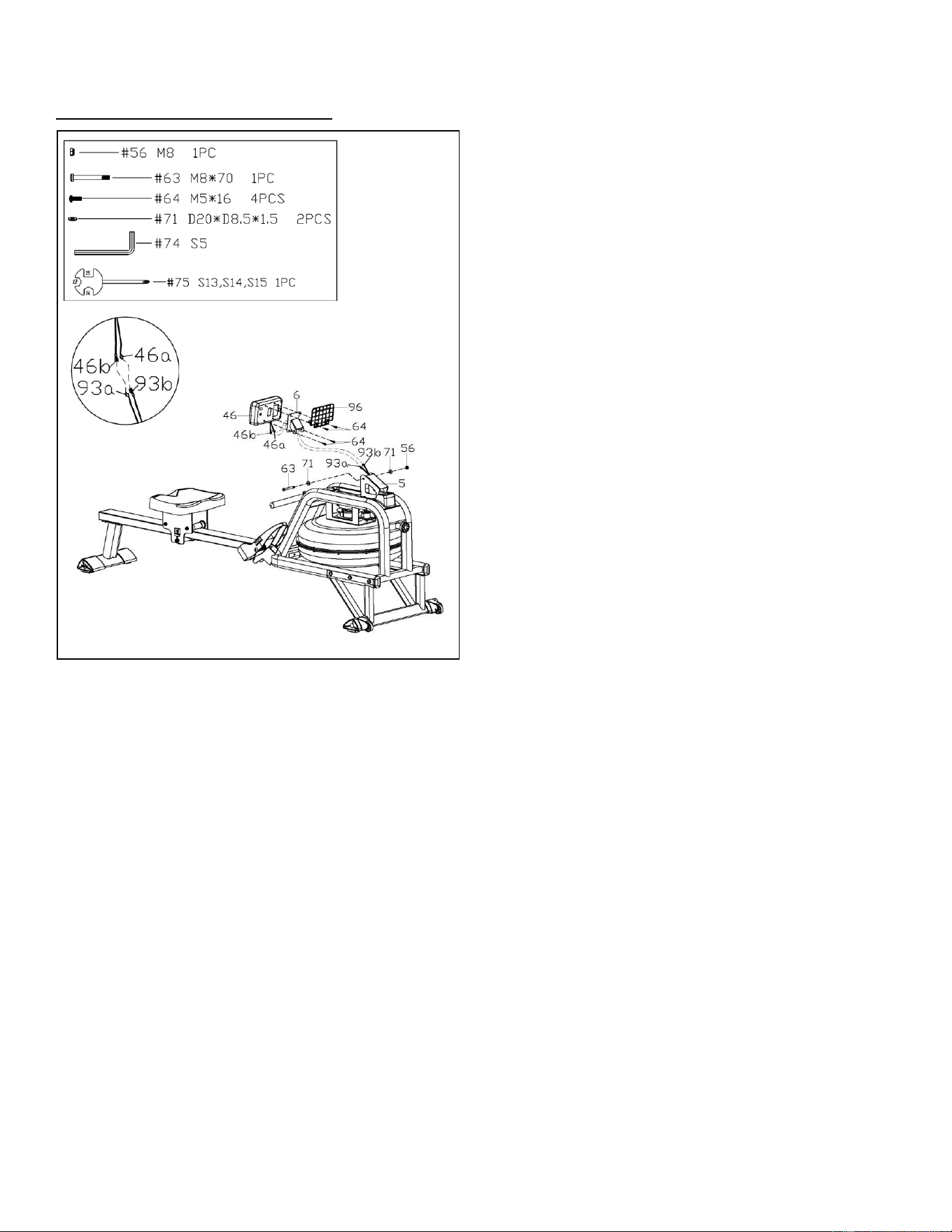
STEP 6:
Remove 4 Screws (No. 64) from the Meter
(No. 46) using Spanner (No. 75).
Pull the Meter Wire A (No. 46a) and Meter
Wire B (No. 46b) through the Support Plate
(No. 6), then lock the Meter (No. 46) and
Tablet Holder (No. 96) to the Support Plate
(No. 6) with 4 Screws (No. 64) that were just
removed. Tighten and secure with Spanner
(No. 75).
Connect the Sensor Wire A (No. 93a) to the
Meter Wire B (No. 46b), connect the Sensor
Wire B (No. 93b) to the Meter Wire A (No.
46a).
Attach Support Plate (No. 6) to Sensor Stand
(No. 5) using 1 Bolt (No. 63), 2 Washers (No.
71), and 1 Nylon Lock Nut (No. 56). Tighten
with Allen Wrench (No. 74) and Spanner (No.
75).
Make sure it is not too tight to adjust the angle
of Meter (No. 46).
The assembly is complete!
7
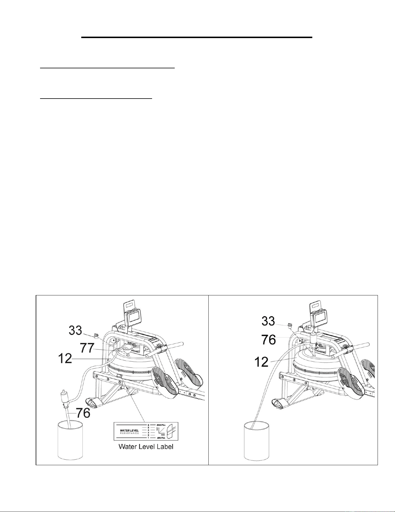
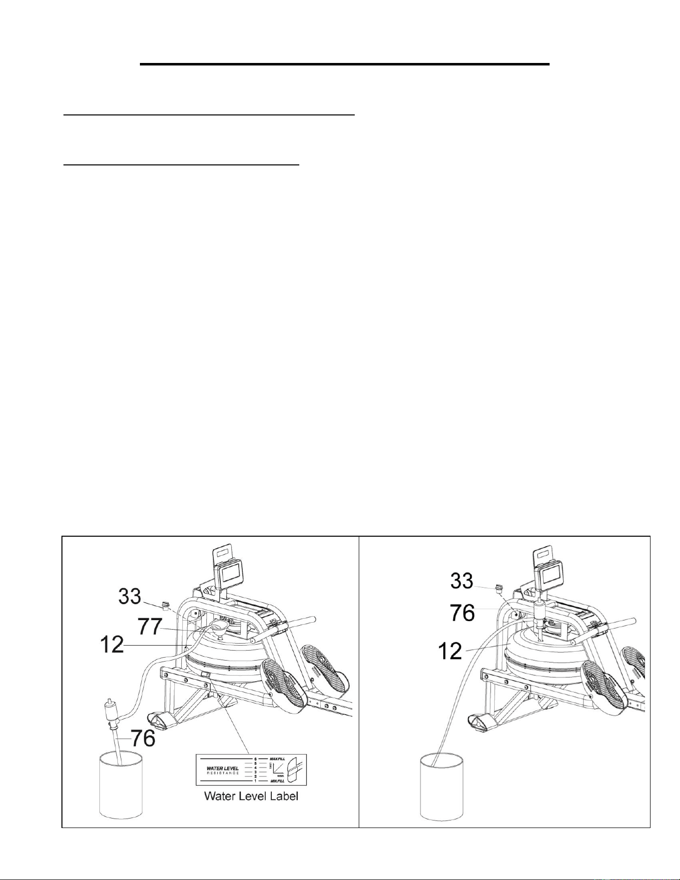
HOW TO FILL AND EMPTY THE TANK
1. Remove the Fill Plug (No. 33) from the Upper Tank Cover (No. 12).
2. To fill the tank with water, refer to Fig. A. Insert the Funnel (No. 77) into the tank, then use a cup
or the Pumping Siphon (No. 76) and a bucket to fill the tank. Use the water level gauge on the
side of the tank to measure desired water level in the tank.
3. To empty the tank, refer to Fig. B. Place a bucket next to the rower, and use the Pumping
Siphon (No. 76) to pump out the water from the tank into the bucket.
4. Insert the Fill Plug (No. 33) into the Upper Tank Cover (No. 12). Wipe excess water off the
frame.
NOTE:
• Fill the tank only with tap water. Add 1 water purification tablet (1 packet is included.). Never
use pool chlorine or chlorine bleach. This will damage the tank and void the warranty.
• Add a water purification tablet every 6 months or as needed. If water remains cloudy, replace the
water in the tank.
• Do not consume the tank water. Dispose of the water after pumping it out from the tank.
WATER LEVEL
• See Fig. A. The water level gauge is on the side of the tank. The maximum fill level is 6.
Never fill over this limit. Filling the tank over this limit will void the warranty.
• The resistance depends on the water level in the tank. Water level 1 is the lowest resistance.
Level 6 is the highest resistance.
Fig. B
Fig. A
8
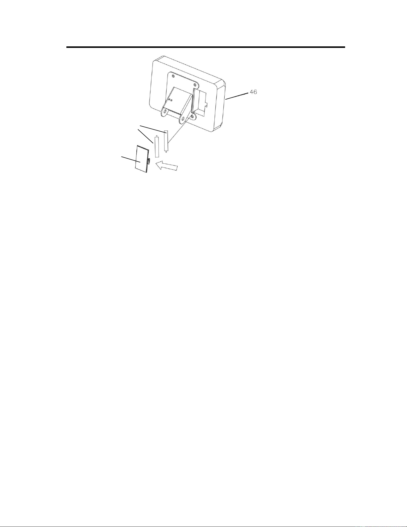
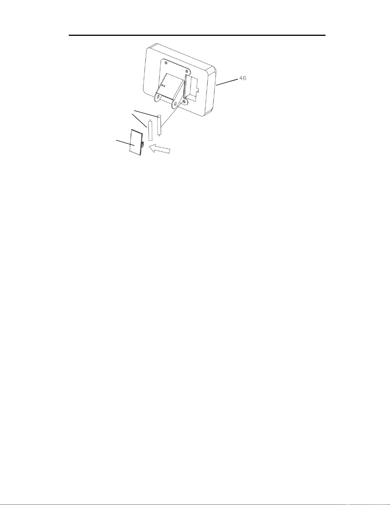
BATTERY INSTALLATION & REPLACEMENT
BATTERY INSTALLATION:
1. Take out 2 AA batteries from the meter box.
2. Press the buckle of battery cover on the back of the Meter (No. 46), then remove battery cover.
3. Install 2 AA batteries into the battery case on the back of the Meter (No. 46). Pay attention to the
battery + and – poles before installing.
4. Press the buckle of battery cover, then put the battery cover back to the back of the Meter (No.
46).
The installation is complete!
BATTERY REPLACEMENT:
1. Press the buckle of battery cover on the back of the Meter (No. 46), then remove battery cover.
2. Remove the 2 old AA batteries in the battery case and install 2 new AA batteries into the battery
case on the back of the Meter (No. 46). Pay attention to the battery + and – poles before installing.
3. Press the buckle of battery cover, then put the battery cover back to the back of the Meter (No.
46).
The replacement is complete!
NOTE: Always change both batteries at the same time. Do not mix battery types and do not mix old
and new batteries. Dispose batteries according to your state and regional guidelines.
Battery Cover
Battery
9
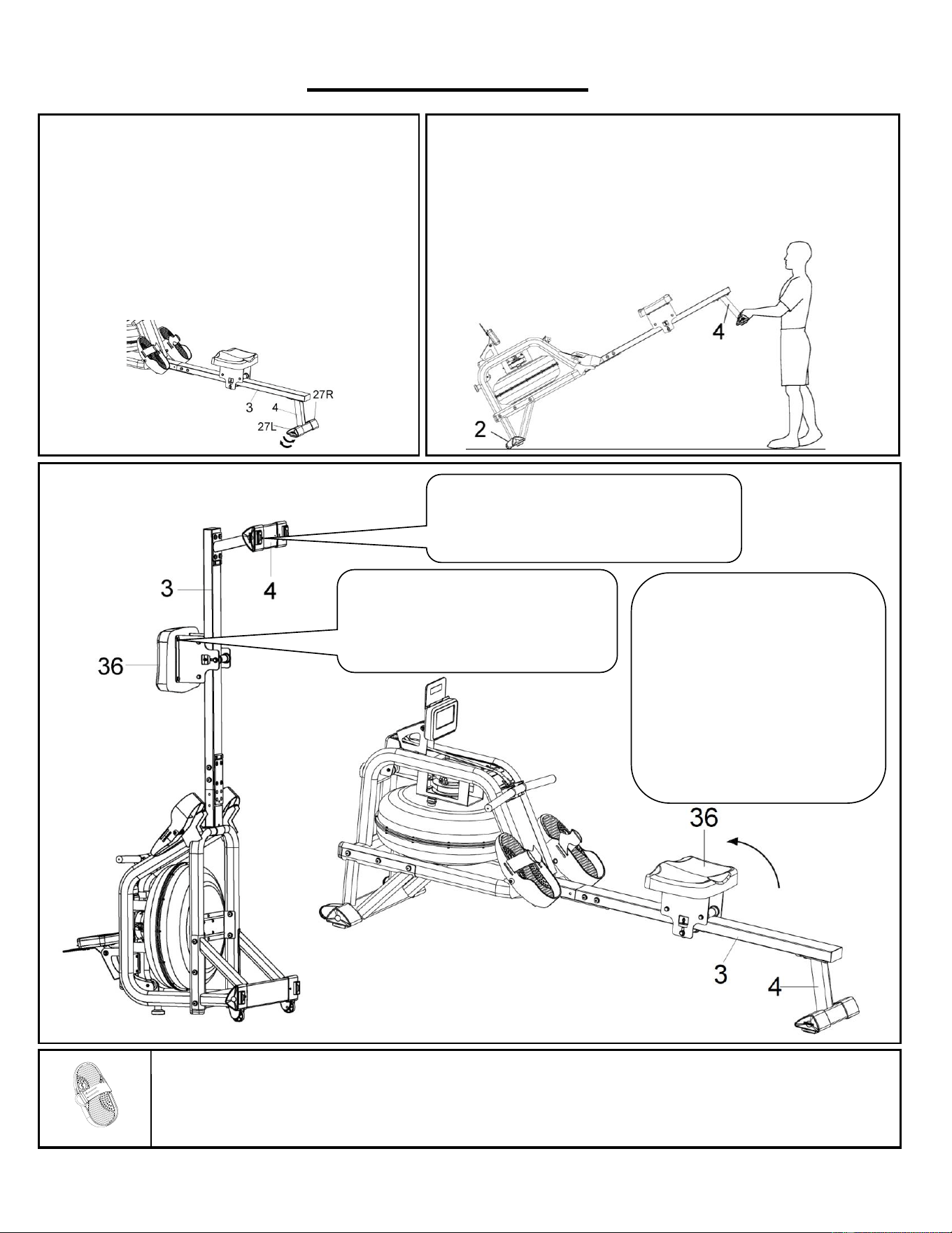
ADJUSTMENTS GUIDE
ADJUSTING THE BALANCE
Adjust the Left & Right Ajustable End Caps (No. 27L
& No. 27R) on the Rear Stabilizer (No. 4) of the rower
if the rower is unbalanced during use.
CAUTION!
Moving parts, such as the seat, can crush and cut.
Keep hands clear of the Slide Rail (No. 3) during use!
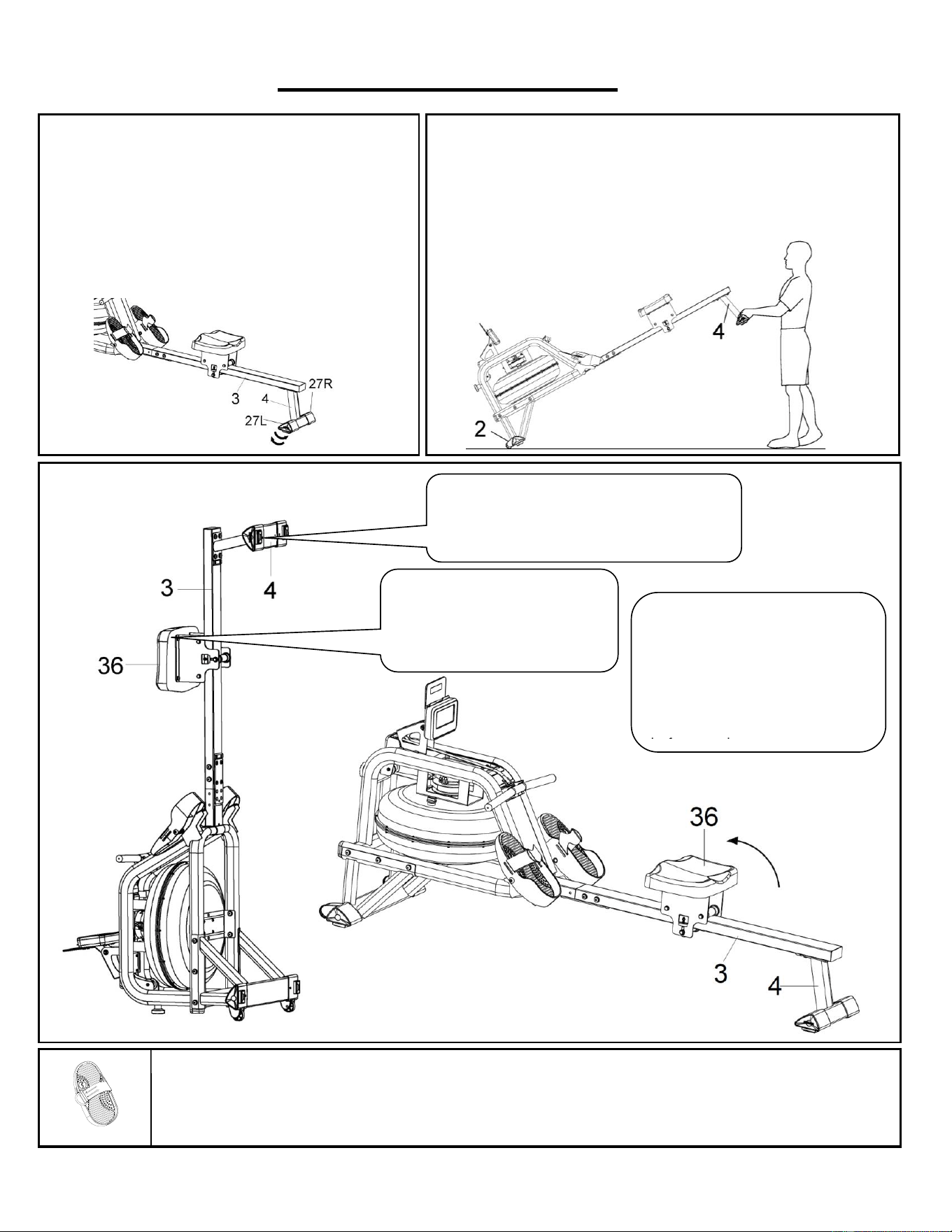
STORAGE
MOVING THE ROWER
To move the rower, lift up the Rear Stabilizer (No. 4) until the
transportation wheels on the Front Stabilizer (No. 2) touch the
ground. With the transportation wheels on the ground, you can
transport the rower to the desired location with ease.
PEDAL ADJUSTMENT
The pedal strap is adjustable and can be personalized to fit the user’s foot size.
CAUTION!
Move with caution when you raise the rower
up, as your head may touch the Rear
Stabilizer (No. 4)
CAUTION!
Move the Seat (No. 36) to the
front of Slide Rail (No. 3) first,
or it will glide down when raising
the rower up!
When not in use, you can
save space by storing the
rower vertically. Lift by the
Rear Stabilizer (No. 4) to
raise the rower to a vertical
position.
If not using the rower for more
than a month, empty the tank
before storing.

10
EXERCISE METER
Our computerized exercise meter on the Sunny Obsidian Surge 500 Meter Water Rowing Machine allows the user to
tailor a personalized workout by monitoring their progress. During a workout, the exercise meter will alternately and
repeatedly display the TIME, TIME/500M, SPM, DISTANCE, STROKES, TOTAL STROKES, CALORIES, and PULSE (all
the above).
FUNCTION BUTTONS
UP▲/ DOWN▼: Press these two buttons to scroll through the available selection.
To adjust the function value upward and downward.
ENTER: To confirm your selection.
During training, press the button to scan each display function.
START/STOP: To start and stop your selected workout program.
RESET: Press the stop button to stop the exercise, short press the RESET button to clear the exercise values (except
TOTAL STROKES).
Press and hold the RESET button for 2 seconds, the meter will reset and all exercise values will be cleared
(except TOTAL STROKES).
If you need to clear the TOTAL STROKES, you can reload the batteries.
RECOVERY: When the heart rate value is displayed on the meter, press the RECOVERY button to start/exit the heart
rate recovery function to evaluate the user's heart rate recovery status.
DISPLAY FUNCTIONS
TIME: (1) Display the time when the user rowed.
(2) In manual mode, set the target rowing time (Setting range 1:00-99:00, setting value ± 1:00).
TIME/500M: Your average 500 meter time will automatically be displayed and continuously updated.
SPM: Strokes per minute.
DISTANCE: (1) Displays the distance the user rowed.
(2) In manual mode, set the target rowing distance (Setting range 100-99900 meters, setting value ± 100
meters).
STROKES: (1) Displays the number of strokes the user rowed.
(2) In manual mode, set the target rowing strokes (Setting range 10-9990 strokes, setting value ± 10 strokes).
TOTAL STROKES: Display the total number of rowing strokes (display range 0-9999 strokes).
CALORIES: (1) Displays the number of calories consumed by the user.
(2) In manual mode, set the target calories consumption (Setting range 10-9990 cal, setting value ± 10 cal).
WATT: Display the user's exercise power.
PULSE: (1) Display the user's current heart rate value. The chest strap heart rate monitor must be worn before testing the
heart rate. Pulse measurement function only works with 5.3KHz chest strap heart rate monitors.
(2) In manual mode, set the target heart rate (Setting range 30-240 BPM, setting value ± 1 BPM).
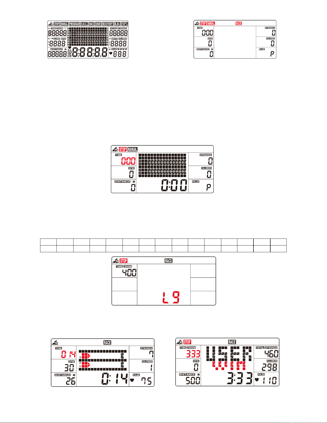
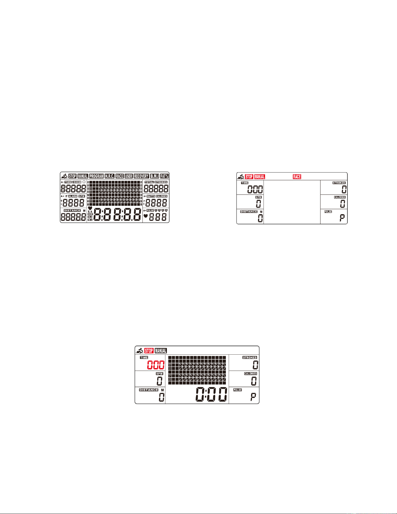
OPERATION
1. Install 2PCS AA batteries (included), meter will beep for 2 seconds, and full screen display for 2 seconds (Fig. 1).
(1) Clock will flash on the meter. Press UP or DOWN buttons to select the hour. Press ENTER button to confirm
your selection. Press UP or DOWN buttons to select the minute. Press ENTER to confirm.
(2) Year will flash on the meter. Press UP or DOWN buttons to select the year. Press ENTER to confirm.
(3) Month will flash on the meter. Press UP or DOWN buttons to select the month. Press ENTER to confirm.
(4) Day will flash on the meter. Press UP or DOWN buttons to select the day. Press ENTER to confirm.
(5) Alarm will display on the meter. If you want to set an alarm, Press UP or DOWN buttons to turn on/off the alarm.
If alarm is set to on, press ENTER, alarm clock will flash. Press UP or DOWN buttons to set your desired alarm.
(6) If no alarm is set, press ENTER, the meter will go into the SPORT screen (Fig. 2).
11
Fig. 1 Fig. 2
2. When you enter the SPORT screen, MANUAL & RACE will flash. Press UP or DOWN buttons to select MANUAL or
RACE. Press ENTER button to confirm your selection.
(1) MANUAL(Fig. 3):
A. Enter into the MANUAL mode, press UP button to set the flickering figure of the TIME. Press ENTER button to
confirm it. Then, you can press UP button to set DISTANCE→STROKES→CALORIES→PULSE→TIME
immediately. (If you have set the target value for TIME, then DISTANCE can’t be set, vice versa.)
B. Press START button to start, the STOP icon will disappear. Press ENTER button to select functions.
C. When the function you have selected counts down to zero or you press the STOP button, the meter will stop
and display the average value. (If the target heart rate value is set, when the user's heart rate value is higher
than the target heart rate value, the meter will give an alarm and the heart rate value will flash.)
Fig. 3
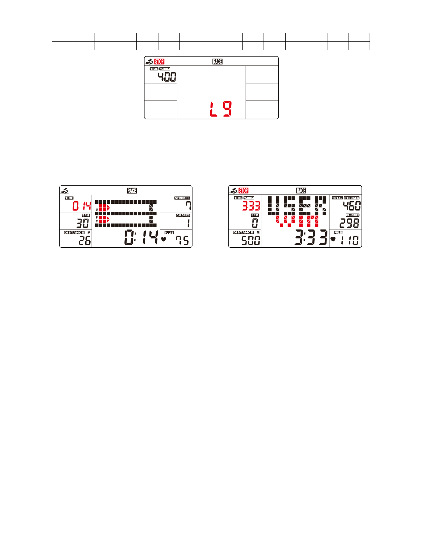
(2) RACE (Fig. 4):
A. Enter into the RACE mode and L9 will flash, the TIME/500M will display 4:00. Then, press UP or DOWN
buttons to select L1 ~ L15. Press ENTER button to confirm. Then, you can set the distance of the race
(500M~10000M) while the value of DISTANCE is blinking.
Press ENTER button and the picture of the race will display on the screen.
The TIME/500M of the programs are as follows:
L1
L2
L3
L4
L5
L6
L7
L8
L9
L10
L11
L12
L13
L14
L15
8:00
7:30
7:00
6:30
6:00
5:30
5:00
4:30
4:00
3:30
3:00
2:30
2:00
1:30
1:00
Fig. 4
B. Press START button to start and STOP will disappear. The USER & PC will display in the matrix (Fig. 5). The
meter will stop when either the user or meter has reached the race distance that was set. Then the matrix
displays “PC WIN” or “USER WIN”(Fig. 6).
Fig. 5 Fig. 6

12
(3) RECOVERY:
1. The meter works with a 5.3 KHz chest strap heart rate monitor (not included). After exercising for a period of
time, keep wearing chest strap monitor and press “RECOVERY” button. All function displays will stop except
“TIME” starts counting down from 00:60 to 00:00.
2. Screen will display your heart rate recovery status with the F1,F2….to F6. F1 is outstanding, F6 is the poor.
User may keep exercising to improve the heart rate recovery status. (Press the RECOVERY button again to
return the main display.)
(4) H.R.C:
A. Enter into the MANUAL mode and press “ENTER” button until the value of PULSE is blinking.
B. Press “UP” and “DOWN” buttons to set exercise pulse. The setting values of 30-240 BPM.
C. The meter alarm and the value of the PULSE is blinking when heart rate is above the SET value.
SLEEP MODE
If no signal is received for 4 minutes and the button is not pressed, the meter will automatically turn off and enter into
sleep mode. Start exercising or press any button and the meter will restart.
BATTERY
This meter uses 2 AA batteries, which are included. Changing the batteries will reset all values.
If there is a problem with the display, try changing the batteries first. When changing the batteries, change both. Do not
mix battery types. Do not mix old and new batteries. Dispose old batteries according to your regional guidelines.
APP CONNECTION:
Connect Smart Equipment to SunnyFit App:
1. Scan to download SunnyFit from the app store:
2. Ensure that the Bluetooth function is turned on from your mobile device.
3. If this is your first time using the SunnyFit app, follow the in-app instructions to register for your free SunnyFit
account and log in.
4. Begin any workout activity that matches your smart equipment, then follow the onscreen prompts to search for
and connect to your smart equipment.
5. When connected, your stats and records will be displayed at the end of your course/session, and recorded in your
account profile!
Troubleshooting:
•
If you are having trouble connecting your smart equipment, visit www.sunnyfit.com/guide or scan the QR code
below:
•
If you require additional support, please contact [email protected].

13
PARTS LIST
No.
Description
Spec.
Qty.
No.
Description
Spec.
Qty.
1
Main Frame
1
48
Sensor Holder
Nylon, Black
1
2
Front Stabilizer
1
49
Magnet
Ø10*5
1
3
Slide Rail
1
50
Casing Pipe for
Mesh Belt Wheel
Ø10*Ø6.2*40
3
4
Rear Stabilizer
1
51
Nylon Lock Nut
M6*H6*S10
10
5
Sensor Stand
1
52
Wave Washer
D10*Ø15*0.3
3
6
Support Plate
1
53
Raw Cotton
Ø96.9*Ø60*20
1
7
Tank Plate
1
54
Axle for Volute
Spring
PA66+20% Fibre
1
8
Connecting Plate
1
55
Screw
M6*15
12
9
Handlebar
1
56
Nylon Lock Nut
M8
6
10
Seat Carriage
SPHC,T=4.0
2
57
Stainless Steel Axle
Ø20*163*M8
1
11
Impeller
1
58
Flat Screw
M8*15
8
12
Upper Tank Cover
PC
1
59
Washer
D8*Ø20*2
1
13
Lower Tank Cover
PC
1
60
Screw
M8*15
30
14
Mesh Belt Disc
1
61
Screw
M3*20
12
15
Mesh Belt Wheel
115*110*34.5
1
62
Nylon Lock Nut
M3
12
16
Screw
M8*60*20 S5
2
63
Bolt
M8*70
1
17
Handlebar Seat
HIPS, Black
1
64
Screw
M5*16
4
18
Roller
POM, Black
3
65
Bolt
M8*125
3
19
Spacer
ABS, Black
3
66
N/A
-
20
Mesh Belt Wheel
POM, Black
3
67
Flat Cross Screw
M6*10
4
21
Volute Spring
T0.5*22*5080
1
68
Cross Screw
M4*12
2
22
PC Board
Ø90*Ø25.2*0.5
1
69
Washer
D8*D24*2
1
23
Left Pedal
PP, Black
1
70
Bolt
M12*135
2
24
Right Pedal
PP, Black
1
71
Washer
D20*D8.5*1.5
34
25
Left End Cap
1
72
Washer
D16*D8.5*1.5
4
26
Right End Cap
1
73
Silicone Pad
80*80*3
2
27L
Left Adjustable
End Cap
1
74
Allen Wrench
S5
1
27R
Right Adjustable
End Cap
1
75
Spanner
S13, S14,S15
1
28
Rail End Cap
PP,Black
1
76
Pumping Siphon
1
29
Oval Plug
PP, Black
2
77
Funnel
1
30
Rubber Sealing
Ring
Ø500*Ø488*7.5
1
78
Lower Tank Plate
1
31
Rubber Sealing
Ring
Ø50*Ø19.5*6
1
79
Hex Nut
M12
2
32
Bearing
6905
1
80
Screw
M8*25
1
33
Fill Plug
Rubber, Black
1
81
C Clip
D10
6
34
N/A
-
82
Stainless Washer
M3
24
35
Stopper
Rubber, Black
2
83
Cross Screw
M6*15
2
36
Seat
PU, Black
1
84
Upper Sealing Ring
Rubber
1
37
Pedal Strap
PP, Black
2
85
Spacer
Ø25*Ø20.2*10
1
38
Mesh Belt
Nylon, Black
1
86
Bolt
M6*55*15*S10
3
39
Screw
M6*35*15*S5
5
87
Protect Cover
532.5*119*166.7
1
40
Bearing
6000
6
88
Foot Pad
Ø52*40*M10
1
41
One-way Bearing
1
89
Adjusting U Seat
30*9*1.5
2
42
Screw
ST4.2*16
7
90
Adjusting Screw
M6*40*Ø10*2.5
2
43
Bearing
608ZZ
6
91
Screw
M8*25*S6
1
44
Alloy Wrap
Copper base
with oil
6
92
Outer PC Board
1
45
Bearing
6904
3
93a
Sensor Wire A
150mm
1
46
Meter
X-6422
1
93b
Sensor Wire B
150mm
1
46a
Meter Wire A
100mm
1
94
Rotating Fixing Seat
1
46b
Meter Wire B
100mm
1
95
Hex Nut
M10
1
47a
Inductor Wire A
400mm
1
96
Tablet Holder
1
47b
Inductor Wire B
400mm
1

14
INFORMACIÓN IMPORTANTE DE SEGURIDAD
Gracias por haber elegido nuestro producto. Para garantizar su seguridad y salud, utilice este
equipo correctamente. Es importante que lea todo el manual antes de instalar y usar el equipo.
Solo se puede garantizar el uso seguro y eficaz del equipo si se instala, mantiene y utiliza
correctamente. Es su responsabilidad asegurarse de que todos los usuarios de los equipos
conozcan todas las advertencias y precauciones.
1. Antes de comenzar algún programa de ejercicios, deberá consultar con su médico para
determinar si tiene alguna condición médica o física que pudiera poner en riesgo su salud y
seguridad o que pudiera impedir que utilice correctamente el equipo. Es importante que reciba
las recomendaciones de su médico en caso de que esté tomando algún medicamento que
pudiera afectar su ritmo cardíaco, presión arterial o nivel de colesterol.
2. Esté atento a las señales que le envía su cuerpo. Ejercitarse de manera incorrecta o excesiva
puede dañar su salud. Deje de hacer ejercicio si experimenta alguno de los siguientes
síntomas: dolor, opresión en el pecho, latidos cardíacos irregulares, falta de aire, sensación de
desmayo, mareos o sensación de náuseas. Si presenta alguna de esas condiciones, deberá
consultar con su médico antes de continuar con su programa de ejercicios.
3. Mantenga el equipo lejos del alcance de niños y mascotas. El equipo está diseñado para el uso
exclusivo de adultos.
4. Utilice el equipo en una superficie plana y sólida con una cubierta protectora para su piso o
alfombra. Para garantizar su seguridad, el equipo debe tener por lo menos 2 pies (60 cm) de
espacio libre a su alrededor.
5. Asegúrese de que todas las tuercas y pernos estén bien ajustados antes de usar el equipo.
Solo puede conservarse la seguridad del equipo si se inspecciona regularmente para detectar
daños o desgaste.
6. Siempre utilice el equipo como se indica. Si encuentra algún componente defectuoso mientras
instala o revisa el equipo, o si escucha ruidos extraños que provienen de este mientras se
ejercita, deje de utilizarlo inmediatamente y no lo utilice hasta que el problema se haya
corregido.
7. Use ropa adecuada cuando utilice el equipo. Evite usar ropa suelta que pueda enredarse en el
equipo.
8. No coloque los dedos u objetos en las piezas móviles del equipo.
9. La capacidad de peso máximo de esta unidad es de 300 libras (135 kgs).
10. Este equipo no es adecuado para uso terapéutico.
11. Muévase con cuidado cuando levante y mueva el equipo. Siempre utilice la técnica de
levantamiento adecuada y pida ayuda en caso de que sea necesario.
12. Su producto está diseñado para usarse en un lugar fresco y seco. Debe evitar tenerlo en
lugares extremadamente fríos, calientes o húmedos, ya que podría provocar corrosión y otros
problemas afines.
13. Este equipo está diseñado solo para uso interior; no es para uso comercial.
15
LISTA DE COMPROBACIÓN PREVIA AL MONTAJE
Antes de empezar a montar, asegúrese de que todas las piezas están incluidas.
n.°
DESCRIPCIÓN
ESPEC
CANT
n.°
DESCRIPCIÓN
ESPEC
CANT
1
Marco Principal
1
46
Medidor
X-6422
1
2
Estabilizador
Delantero
1
76
Sifón de Bombeo
1
3
Riel Deslizante
1
77
Embudo
1
4
Estabilizador
Trasero
1
96
Soporte para
Tabletas
1
5
Soporte del
Sensor
1
A
Manual
1
6
Placa de Soporte
1
B
Tarjeta de
Agradecimiento
1
25
Tapa del Extremo
Izquierdo
1
C
Paquete de
Hardware
1
26
Tapa del Extremo
Derecho
1
D
Batería
AA
2
36
Asiento
PU, Negro
1
16
PAQUETE DE HARDWARE
Pedido de piezas de repuesto (sólo para clientes de EE.UU. y Canadá)
Proporcione la siguiente información para que podamos identificar con precisión la(s) pieza(s)
necesaria(s):
✓ El número de modelo (se encuentra en la portada del manual)
✓ Nombre del producto (en la portada del manual)
✓ El número de pieza que se encuentra en el "DIAGRAMA EXPLÍCITO" (páginas 28~29) y en la
"LISTA DE PIEZAS" (página 27)
Póngase en contacto con nosotros en [email protected] o en el 1-877-90SUNNY
(877-907-8669).
17
INSTRUCCIONES DE MONTAJE
Valoramos su experiencia con los productos Sunny Health and Fitness. Para obtener ayuda con las
piezas o la resolución de problemas, póngase en contacto con nosotros en
[email protected] o en el 1-877-90SUNNY (877-907-8669).
PASO 1:
NOTA: Recomendamos que sean 2 personas
que armen el producto.
Gire el Riel Deslizante (n.° 3) y el Asiento (n.°
36) como se muestra en la foto.
Deslice el Asiento (n.° 36) en el Riel
Deslizante (n.° 3). Asegure el Tapón (n.° 35)
con 2 Tornillos de Cabeza de Cruz Plana (n.°
67). Ajuste con una Llave Inglesa (n.° 75).
Luego, conecte el Estabilizador Trasero (n.°
4) al Riel Deslizante (n.° 3) con 4 Arandelas
(n.° 71) y 4 Tornillos (n.° 60). Ajuste con una
Llave Allen (n.° 74).
PASO 2:
Fije las Tapas del Extremos Izquierdo y
Derecho (n.° 25 y n.° 26) al Estabilizador
Delantero (n.° 2). Luego, ajuste con 2
Tornillos de Cabeza de Cruz Plana (n.° 68) y
una Llave Inglesa (n.° 75).
PASO 3:
Mantenga el Marco Principal (n.° 1) en
posición vertical. Fije el Estabilizador
Delantero (n.° 2) al Marco Principal (n.° 1)
con 6 Arandelas (n.° 71) y 6 Tornillos (n.°
60). Primero inserte los 6 Tornillos (n.° 60)
parcialmente en los orificios y luego ajuste con
la Llave Allen (n.° 74).

18
Valoramos su experiencia con los productos Sunny Health and Fitness. Para obtener ayuda con las
piezas o la resolución de problemas, póngase en contacto con nosotros en
PASO 4:
NOTA: Mueva el Asiento (n.° 36) a la parte
delantera del Riel Deslizante (n.° 3) antes del
armado, para evitar que se deslice hacia abajo
durante el proceso.
Fije el Riel Deslizante (n.° 3) al Marco
Principal (n.° 1) con 4 Arandelas (n.° 71), 4
Tornillos (n.° 60) y 4 Tornillos de Cabeza
Plana (n.° 58). Primero inserte los 8 tornillos
parcialmente en los orificios y luego ajuste con
la Llave Allen (n.° 74).
PASO 5:
Conecte el Cable Inductor A (n.° 47a) al
Cable del Sensor A (n.° 93a), conecte el
Cable Inductor B (n.° 47b) al Cable del
Sensor B (n.° 93b).
Fije el Soporte del Sensor (n.° 5) al Marco
Principal (n.° 1) con 4 Arandelas (n.° 71) y 4
Tornillos (n.° 60). Ajuste con una Llave Allen
(n.° 74).
Si está sentado en el asiento, la flecha
adhesiva en el Soporte del Sensor (n.° 5)
debe apuntar hacia usted. Esto significa que el
Soporte del Sensor (n.° 5) está instalado en
la dirección correcta.
19
Valoramos su experiencia con los productos Sunny Health and Fitness. Para obtener ayuda con las
piezas o la resolución de problemas, póngase en contacto con nosotros en
PASO 6:
Retire los 4 Tornillos (n.º 64) del Medidor (n.º
46) con la Llave Inglesa (n.º 75).
Tire del Cable de Medidor A (n.° 46a) y del
Cable de Medidor B (n.° 46b) a través de la
Placa de Soporte (n.° 6), luego fije el Medidor
(n.° 46) y el Soporte para Tabletas (n.° 96) a
la Placa de Soporte (n.° 6) con los 4
Tornillos (n.° 64) que acaba de retirar.
Apriételos y fíjelos con la Llave Inglesa (n.°
75).
Conecte el Cable del Sensor A (n.° 93a) al
Cable de Medidor B (n.° 46b), conecte el
Cable del Sensor B (n.° 93b) al Cable de
Medidor A (n.° 46a).
Fije la Placa de Soporte (n.º 6) al Soporte del
Sensor (n.º 5) utilizando 1 Perno (n.º 63), 2
Arandelas (n.º 71) y 1 Tuerca de Bloqueo de
Nailon (n.º 56). Apriete con la Llave Allen (n.º
74) y la Llave Inglesa (n.º 75).
Asegúrese de que no esté demasiado ajustado
para ajustar el ángulo del Medidor (n.° 46).
¡El armado está completo!
20
CÓMO LLENAR Y VACIAR EL TANQUE
1. Retire el Tapón del Tanque (n.° 33) de la Cubierta Superior del Tanque (n.° 12).
2. Para llenar el tanque con agua, consulte la Fig. A. Inserte el Embudo (n.° 77) en el tanque,
luego use una taza o la Sifón de Bombeo (n.° 76) y un balde para llenar el tanque. Utilice el
indicador de nivel de agua en el lado del tanque para medir el nivel de agua deseado.
3. Para vaciar el tanque, consulte la Fig. B. Coloque un balde al lado de la remadora, y utilice la
Sifón de Bombeo (n.° 76) para bombear el agua del tanque al balde.
4. Inserte el Tapón del Tanque (n.° 33) en la Cubierta Superior del Tanque (n.° 12). Limpie el
exceso de agua del marco.
NOTA:
• Llene el tanque solo con agua entubada. Agregue 1 tableta de purificación de agua (se
incluye 1 paquete). Nunca use cloro de piscina o lejía de cloro. Esto dañará el tanque y anulará
la garantía.
• Agregue una tableta de purificación de agua cada 6 meses o según sea necesario. Si el agua
permanece turbia, reemplace el agua del tanque.
• El agua del tanque no es adecuada para consumir. Deseche el agua después de sacarla del
tanque.
NIVEL DEL AGUA
• Vea la Fig. A. El indicador de nivel de agua está en el lado del tanque. El nivel de llenado
máximo es 6. Nunca llene por encima de este límite. Si el tanque se llena por encima de este
límite, anulará la garantía.
• La resistencia depende del nivel de agua en el tanque. El nivel 1 de agua es la resistencia
más baja. El nivel 6 de agua es la resistencia más alta.
Fig. B
Fig. A
21
INSTALACIÓN Y REEMPLAZO DE LA PILA
INSTALACIÓN DE LA PILA:
1. Saque 2 pilas AA de la parte posterior del Medidor (n.° 46).
2. Presione la hebilla de la tapa de la pila en la parte posterior del Medidor (n.° 46), luego retire la
tapa de la pila.
3. Instale 2 pilas AA en la caja de la pila en la parte posterior del Medidor (n.° 46). Preste atención
a los polos + y - de la pila antes de instalar.
4. Presione la hebilla de la cubierta de la pila, luego coloque la cubierta de la pila en la parte
posterior del Medidor (n.° 46).
5. ¡La instalación está completa!
REEMPLAZO DE LA PILA:
1. Presione la hebilla de la tapa de la batería en la parte posterior del Medidor (n.° 46), luego retire la
tapa de la batería.
2. Retire las 2 pilas AA viejas del estuche de las pilas e instale 2 pilas AA nuevas en el estuche de
las pilas en la parte posterior del Medidor (n.° 46). Preste atención a los polos + y - de las pilas
antes de instalarlas.
3. Presione la hebilla de la tapa de las pilas y vuelva a colocar la tapa de las pilas en la parte
posterior del Medidor (n.° 46).
La sustitución se ha completado!
NOTA: Siempre cambie ambas pilas al mismo tiempo. No mezcle tipos de pilas y no mezcle pilas
viejas y nuevas. Deseche las pilas de acuerdo con las regulaciones estatales y regionales.
Tapa de la Pila
r
Pila
22
GUÍA DE AJUSTES
AJUSTE DEL BALANCE
Ajuste la Tapas del Extremo Ajustable Izquierdo &
Derecha (n.° 27L & n.° 27R) en el Estabilizador
Trasero (n.° 4) del remo si éste se desequilibra durante
el uso.
¡PRECAUCIÓN!
Las partes móviles, como el asiento, pueden aplastar y
cortar. Mantenga las manos alejadas del Riel
Deslizante (n.° 3) durante el uso.
ALMACENAMIENTO
TRASLADO DE LA MÁQUINA
Para mover el remo, levante el Estabilizador Trasero (n.° 4) hasta
que las ruedas de transporte del Estabilizador Delantero (n.° 2)
toquen el suelo. Con las ruedas en el suelo, puede transportar el
remo al lugar deseado con facilidad.
AJUSTE DEL PEDAL
La correa del pedal es ajustable y se puede personalizar para adaptarse al tamaño del pie del usuario.
¡PRECAUCIÓN!
Muévase con cuidado cuando levante la
remadora, ya que su cabeza puede tocar el
Estabilizador Trasero (n.° 4).
¡PRECAUCIÓN!
Mueva primero el Asiento (n.° 36) a la
parte delantera del Riel Deslizante
(n.° 3) o se deslizará hacia abajo
cuando levante la remadora.
Cuando no esté en uso, puede
ahorrar espacio al guardar la
remadora verticalmente. Levante el
Estabilizador Trasero (n.° 4) para
poner la remadora en posición
vertical.
Si no usa la remadora durante más
de un mes, vacíe el depósito antes
de guardarla.

23
MEDIDOR DE EJERCICIO
La consola de visualización computarizada de la Obsidian Surge Máquina de Remo de 500 m de Sunny permite que el
usuario realice un entrenamiento personalizado y
supervise su progreso. Durante un entrenamiento, la consola de
visualización mostrará de forma alterna y repetida su TIME (TIEMPO), TIME (TIEMPO)/500 M, SPM, DISTANCE (DISTANCIA),
STROKES (LATIDOS), TOTAL STROKES (LATIDOS TOTALES), CALORIES (CALORÍAS), WATT (VATIOS), y PULSE
(PULSO) (todo lo anterior).
BOTONES DE FUNCIÓN
UP▲/ DOWN▼(ARRIBA▲/ABAJO▼): Pulse estos dos botones para desplazarse por la selección disponible.
Para ajustar el valor de la función hacia arriba y hacia abajo.
ENTER (INGRESAR): Para confirmar su selección.
Durante el entrenamiento, pulse el botón para explorar cada función de la pantalla.
START/STOP (INICIAR/DETENER): Para iniciar y detener el programa de entrenamiento seleccionado.
RESET (RECUPERACIÓN): Pulse el botón Stop para detener el ejercicio, pulse brevemente el botón RESET
(RECUPERACIÓN) para borrar los valores del ejercicio [excepto las TOTAL STROKES
(LATIDOS TOTALES)].
Mantenga pulsado el botón RESET durante 2 segundos, el medidor se reiniciará y se
borrarán todos los valores del ejercicio [excepto las TOTAL STROKES (LATIDOS
TOTALES)].
Si necesita borrar las TOTAL STROKES (LATIDOS TOTALES), puede recargar las pilas.
RECOVERY (RECUPERACIÓN): Cuando aparezca el valor de la frecuencia cardíaca en el medidor, pulse el botón
RECOVERY (RECUPERACIÓN) para iniciar/salir de la función de recuperación de la
frecuencia cardíaca y evaluar el estado de recuperación de la frecuencia cardíaca del
usuario.
FUNCIONES DE VISUALIZACIÓN
TIME (TIEMPO): (1) Muestra el tiempo de remo del usuario.
(2) En modo manual, ajuste el tiempo de remo objetivo (intervalo de ajuste 1:00-99:00, valor de ajuste
± 1:00).
TIME (TIEMPO)/500M: Su tiempo medio de 500 metros se mostrará automáticamente y se actualizará continuamente.
SPM: Latidos por minuto.
DISTANCE (DISTANCIA): (1) Muestra la distancia recorrida por el usuario.
(2) En modo manual, ajuste la distancia de remo objetivo (Rango de ajuste 100-99900 metros,
valor de ajuste ± 100 metros).
STROKES (LATIDOS): (1) Muestra el número de latidos que ha remado el usuario.
(2) En modo manual, establezca las latidos de remo objetivo (Rango de ajuste 10-9990 latidos,
valor de ajuste ± 10 latidos).
TOTAL STROKES (LATIDOS TOTALES): Muestra el número total de latidos de remo (rango de visualización 0-9999
latidos).
CALORIES (CALORÍAS): (1) Muestra el número de calorías consumidas por el usuario.
(2) En modo manual, ajuste el objetivo de consumo de calorías (rango de ajuste
10-9990 cal, valor de ajuste ± 10 cal).
WATT (VATIOS): Muestra la potencia de ejercicio del usuario.
PULSE (PULSO): (1) Muestra el valor actual de la frecuencia cardíaca del usuario. Antes de comprobar la frecuencia
cardíaca, es necesario llevar puesto el pulsómetro. La función de medición del pulso sólo funciona
con pulsómetros de pecho de 5,3KHz.
(2) En modo manual, ajuste la frecuencia cardíaca objetivo (rango de ajuste 30-240 BPM, valor de
ajuste ± 1 BPM).
24
OPERATION (OPERACIÓN)
1. Instale 2 pilas AA (incluidas) y el medidor emitirá un pitido durante 2 segundos (Fig. 1).
(1) El reloj parpadeará en el medidor. Pulse los botones UP (ARRIBA) o DOWN (ABAJO) para seleccionar la hora.
Pulse ENTER (INGRESAR) para confirmar la selección. Pulse los botones UP (ARRIBA) o DOWN (ABAJO)
para seleccionar el minuto. Pulse ENTER (INGRESAR) para confirmar.
(2) El año parpadea en el indicador. Pulse los botones UP (ARRIBA) o DOWN (ABAJO) para seleccionar el año.
Pulse ENTER (INGRESAR) para confirmar.
(3) El mes parpadea en el indicador. Pulse los botones UP (ARRIBA) o DOWN (ABAJO) para seleccionar el mes.
Pulse ENTER (INGRESAR) para confirmar.
(4) El día parpadea en el medidor. Pulse los botones UP (ARRIBA) o DOWN (ABAJO) para seleccionar el día.
Pulse ENTER (INGRESAR) para confirmar.
(5) La alarma aparecerá en el medidor. Si desea ajustar una alarma, pulse los botones UP (ARRIBA) o DOWN
(ABAJO) para activar/desactivar la alarma. Si la alarma está activada, pulse ENTER (INGRESAR), el
despertador parpadeará. Pulse los botones UP (ARRIBA) o DOWN (ABAJO) para ajustar la alarma que desee.
(6) Si no se ajusta ninguna alarma, pulse ENTER (INGRESAR), el medidor pasará a la pantalla SPORT (Fig. 2).
Fig. 1 Fig. 2
2. Al entrar en la pantalla SPORT, MANUAL y RACE (CARRERA) parpadearán. Pulse UP (ARRIBA) o DOWN
(ABAJO) para seleccionar MANUAL o RACE (CARRERA). Pulse ENTER (INGRESAR) para confirmar su selección.
(7) MANUAL (Fig. 3):
A. Entre en el modo MANUAL, pulse el botón UP (ARRIBA) para ajustar la cifra parpadeante de la TIME
(TIEMPO). Pulse el botón ENTER (INGRESAR) para confirmarlo. A continuación, puede pulsar el botón UP
para ajustar DISTANCE (DISTANCIA)→STROKES (LATIDOS)→CALORIES (CALORÍAS)→PULSE
(PULSO)→TIME (TIEMPO) inmediatamente. (Si ha ajustado el valor objetivo para el TIEMPO, entonces no
se podrá ajustar la DISTANCIA, y viceversa).
B. Pulse el botón START (INICIAR) para empezar, el icono STOP (DETENER) desaparecerá. Pulse el botón
ENTER (INGRESAR) para seleccionar las funciones.
C. Cuando la función seleccionada llegue a cero o pulse el botón STOP (DETENER), el medidor se detendrá y
mostrará el valor medio. (Si se establece el valor objetivo de la frecuencia cardíaca, cuando el valor de la
frecuencia cardíaca del usuario sea superior al valor objetivo de la frecuencia cardíaca, el medidor emitirá
una alarma y el valor de la frecuencia cardíaca parpadeará).
Fig. 3
(8) RACE (CARRERA) (Fig. 4):
A. Seleccione el modo RACE (CARRERA) y L9 parpadeará. TIME (TIEMPO) /500M mostrará 4:00. A continuación,
pulse UP (ARRIBA) o DOWN (ABAJO) para seleccionar de L1 a L15. Pulse ENTER (INGRESAR) para confirmar.
A continuación, puede establecer la distancia de la carrera (de 500 M a 10000 M) mientras el valor de
DISTANCE parpadea.
Pulse ENTER (INGRESAR) y la imagen de la carrera aparecerá en la pantalla.
25
Los valores para TIME (TIEMPO) /500M de los programas son los siguientes:
L1
L2
L3
L4
L5
L6
L7
L8
L9
L10
L11
L12
L13
L14
L15
8:00
7:30
7:00
6:30
6:00
5:30
5:00
4:30
4:00
3:30
3:00
2:30
2:00
1:30
1:00
Fig. 4
B. Pulse el botón de START (INICIAR) para iniciar y STOP (DETENER) desaparecerá. USER (USUARIO) y
PC (COMPUTADORA) se mostrarán en la matriz (Fig. 5). La computadora se detendrá cuando el usuario o
la computadora haya alcanzado la distancia de carrera que se estableció. A continuación, la matriz
muestra "PC WIN" ("GANA LA PC") o "USER WIN" ("GANA EL USUARIO") (Fig. 6).
Fig. 5 Fig. 6
(9) RECOVERY (RECUPERACION):
A. Este medidor funciona con un monitor de frecuencia cardíaca con correa de pecho de 5.3 kHz (no incluido).
Después de hacer ejercicio durante un período, siga usando el monitor con correa de pecho y pulse el botón
"RECOVERY (RECUPERACION)". Todas las pantallas funcionales se detendrán, salvo que " TIME
(TIEMPO)" comienza a contar desde 00:60 hasta 00:00.
B. La pantalla mostrará su estado de recuperación del ritmo cardíaco con F1, F2 hasta F6. F1 es excepcional.
F6 es pobre. El usuario puede seguir haciendo ejercicio para mejorar el estado de recuperación del ritmo o
cardíaco. (Pulse nueva nuevamente el botón RECOVERY (RECUPERACION) para volver a la pantalla
principal).
(10) H.R.C:
A. Entre en el modo MANUAL y pulse el botón ENTER (INGRESAR) hasta que el valor de PULSE (PULSO)
parpadee.
B. Pulse los botones UP (ARRIBA) y DOWN (ABAJO) para ajustar el pulso del ejercicio. Los valores de ajuste
de 30-240 BPM.
C. La alarma del medidor y el valor del PULSE (PULSO) parpadean cuando la frecuencia cardiaca está por
encima del valor SET.
SLEEP MODE (MODO DE SUSPENSIÓN)
Si no se recibe ninguna señal durante 4 minutos y no se pulsa el botón, el medidor se apagará automáticamente y
entrará en modo de reposo. Inicie el ejercicio o pulse cualquier botón y el medidor se reiniciará.
BATTERY (PILA)
Este medidor utiliza 2 pilas AA, que están incluidas. Si cambia las pilas, se restablecerán todos los valores.
Si hay un problema con la pantalla, intente cambiar las pilas primero. Cuando cambie las pilas, cambie ambas. No
mezcle diferentes tipos de pilas. No mezcle pilas viejas y nuevas. Deseche las pilas viejas de acuerdo con sus directrices
regionales.
26
CONEXIÓN A LA APP:
Conecte el equipo inteligente a la SunnyFit App:
1. Escanee para descargar SunnyFit de la tienda de aplicaciones:
2. Asegúrese de que la función Bluetooth está activada desde su dispositivo móvil.
3. Si es la primera vez que utiliza la aplicación SunnyFit, siga las instrucciones de la aplicación
para registrarse en su cuenta gratuita de SunnyFit e inicie sesión.
4. Comience cualquier actividad de entrenamiento que coincida con su equipo inteligente y, a
continuación, siga las indicaciones en pantalla para buscar y conectarse a su equipo
inteligente.
5. Una vez conectado, sus estadísticas y récords se mostrarán al final de su curso/sesión y se
registrarán en el perfil de su cuenta!
Solución de problemas:
⚫
Si tienes problemas para conectar tu equipo inteligente, visita www.sunnyfit.com/guide o
escanea el siguiente código QR:
•
Si necesitas más ayuda, ponte en contacto con [email protected].

27
LISTA DE PIEZAS
n.°
DESCRIPCIÓN
ESPEC
CANT
n.°
DESCRIPCIÓN
ESPEC
CANT
1
Marco Principal
1
48
Soporte del Sensor
Nailon, Negro
1
2
Estabilizador Delantero
1
49
Imán
Ø10*5
1
3
Riel Deslizante
1
50
Tubería de Cubierta Para
Rueda de Correa de Malla
Ø10*Ø6.2*40
3
4
Estabilizador Trasero
1
51
Tuerca de Bloqueo de Nailon
M6*H6*S10
10
5
Soporte del Sensor
1
52
Arandela
D10*Ø15*0.3
3
6
Placa de Soporte
1
53
Algodón En Bruto
Ø96.9*Ø60*20
1
7
Placa del Tanque
1
54
Eje del Resorte de Voluta
PA66+20% Fibre
1
8
Placa de Conexión
1
55
Tornillo
M6*15
12
9
Manubrio
1
56
Tuerca de Bloqueo de Nailon
M8
6
10
Soporte de Asiento
SPHC,T=4.0
2
57
Eje de Acero Inoxidable
Ø20*163*M8
1
11
Impulsor
1
58
Tornillo de Cabeza Plana
M8*15
8
12
Cubierta Superior del
Tanque
PC
1
59
Arandela
D8*Ø20*2
1
13
Cubierta Inferior del
Tanque
PC
1
60
Tornillo
M8*15
30
14
Disco de Correa de Malla
1
61
Tornillo
M3*20
12
15
Rueda de Correa de Malla
115*110*34.5
1
62
Tuerca de Bloqueo de Nailon
M3
12
16
Tornillo
M8*60*20 S5
2
63
Perno
M8*70
1
17
Asiento del Manubrio
HIPS, Negro
1
64
Tornillo
M5*16
4
18
Rodillo
POM, Negro
3
65
Perno
M8*125
3
19
Espaciador
ABS, Negro
3
66
N/A
-
20
Rueda de Correa de Malla
POM, Negro
3
67
Tornillo de Cabeza de Cruz
Plana
M6*10
4
21
Resorte de Voluta
T0.5*22*5080
1
68
Tornillo de Cabeza de Cruz
Plana
M4*12
2
22
Tablero de Plástico
Para Rueda de Correa de
Malla
Ø90*Ø25.2*0.5
1
69
Arandela
D8*D24*2
1
23
Pedal Izquierdo
PP, Black
1
70
Perno
M12*135
2
24
Pedal Derecho
PP, Black
1
71
Arandela
D20*D8.5*1.5
34
25
Tapa del Extremo
Izquierdo
1
72
Arandela
D16*D8.5*1.5
4
26
Tapa del Extremo Derecho
1
73
Almohadilla de Silicon
80*80*3
2
27L
Tapa del Extremo
Ajustable Izquierdo
1
74
Llave Allen
S5
1
27R
Tapa del Extremo
Ajustable Derecho
1
75
Llave Inglesa
S13, S14,S15
1
28
Tapa del Extremo del Riel
PP, Negro
1
76
Sifón de Bombeo
1
29
Tapón Oval
PP, Negro
2
77
Embudo
1
30
Anillo de Sellado de Goma
Ø500*Ø488*7.5
1
78
Placa Inferior del Tanque
1
31
Anillo de Sellado de Goma
Ø50*Ø19.5*6
1
79
Tuerca Hexagonal
M12
2
32
Rodamiento
6905
1
80
Tornillo
M8*25
1
33
Tapón del Tanque
Goma,Negro
1
81
Sujetador C
D10
6
34
N/A
-
82
Arandela Inoxidable
M3
24
35
Tapón
Goma, Negro
2
83
Tornillo Phillips
M6*15
2
36
Asiento
PU, Negro
1
84
Anillo de Sellado Superior
Caucho
1
37
Correa de Pedal
PP, Negro
2
85
Espaciador
Ø25*Ø20.2*10
1
38
Correa de Malla
Nailon, Negro
1
86
Perno
M6*55*15*S10
3
39
Tornillo
M6*35*15*S5
5
87
Cubierta Protectora
532.5*119*166.7
1
40
Rodamiento
6000
6
88
Almodilla de Pie
Ø52*40*M10
1
41
Cojinete Unidireccional
1
89
Ajuste U de Asiento
30*9*1.5
2
42
Tornillo
ST4.2*16
7
90
Tornillo de Ajuste
M6*40*Ø10*2.5
2
43
Rodamiento
608ZZ
6
91
Tornillo
M8*25*S6
1
44
Envoltura de Aleación
Base de cobre en
aceite
6
92
Tablero Externo de Plástico
1
45
Rodamiento
6904
3
93a
Cable del Sensor A
150mm
1
46
Medidor
X-6422
1
93b
Cable del Sensor B
150mm
1
46a
Cable de Medidor A
100mm
1
94
Asiento de Fijación Giratorio
1
46b
Cable de Medidor B
100mm
1
95
Tuerca Hexagonal
M10
1
47a
Cable Inductor A
400mm
1
96
Soporte para Tabletas
1
47b
Cable Inductor B
400mm
1
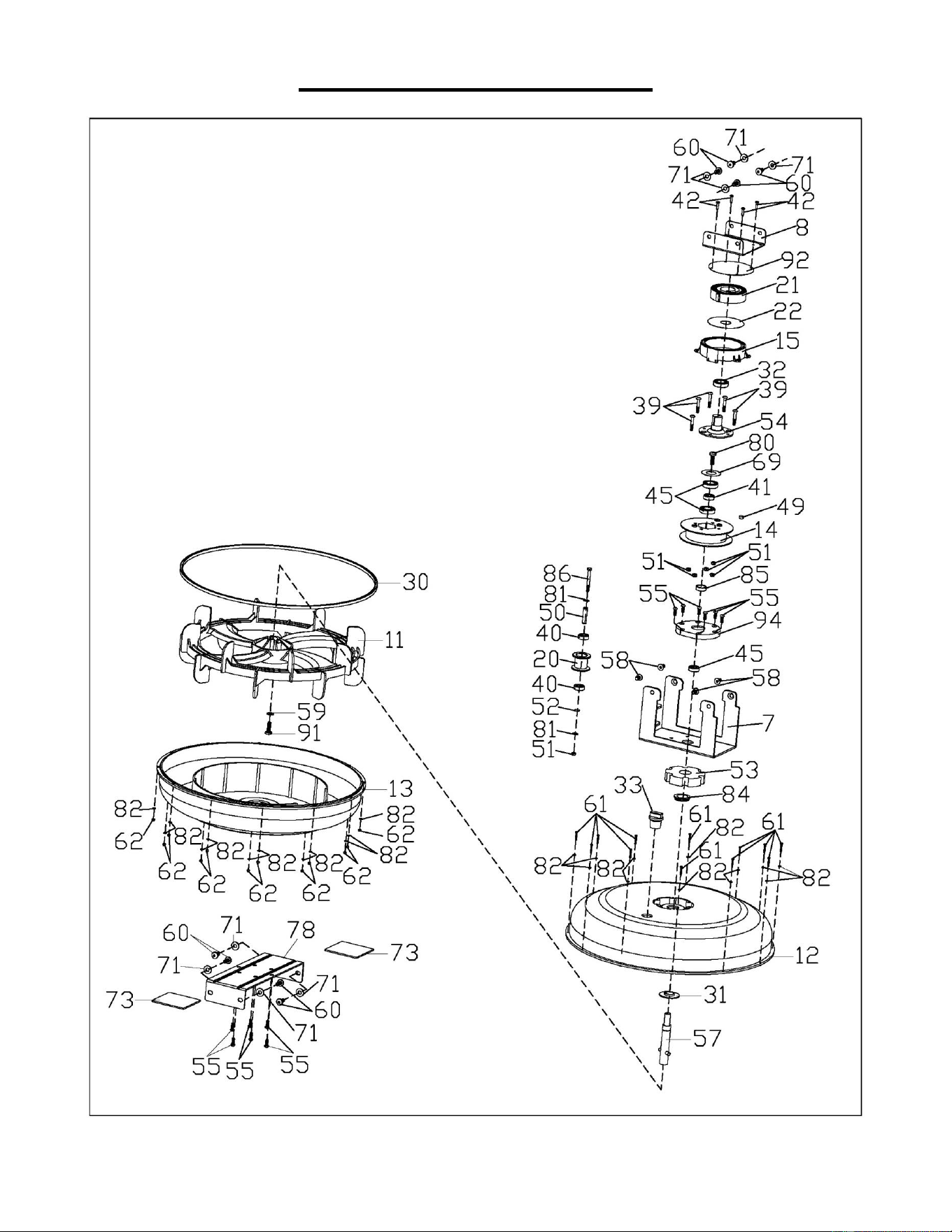
28
EXPLODED DIAGRAM 1
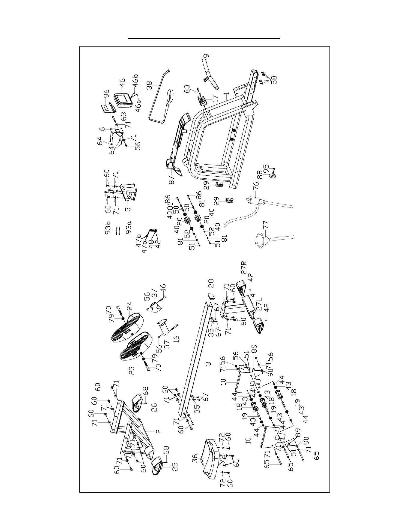
29
EXPLODED DIAGRAM 2
Version: 2.2