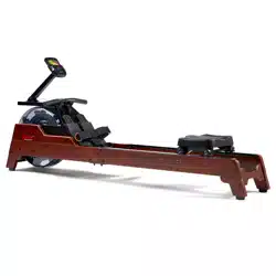
WOODEN WATER ROWING MACHINE
SF-RW522074
USER MANUAL
IMPORTANT! Please retain owner’s manual for maintenance and adjustment instructions. Your
satisfaction is very important to us, PLEASE DO NOT RETURN UNTIL YOU HAVE CONTACTED
US: support@sunnyhealthfitness.com or 1-877-90SUNNY (877-907-8669).

1
IMPORTANT SAFETY INFORMATION
We thank you for choosing our product. To ensure your safety and health, please use this equipment
correctly. It is important to read this entire manual before assembling and using the equipment. Safe and
effective use can only be achieved if the equipment is assembled, maintained and used properly. It is
your responsibility to ensure that all users of the equipment are informed of all warnings and
precautions.
1. Before starting any exercise program, you should consult your physician to determine if you have any
medical or physical conditions that could put your health and safety at risk, or prevent you from using
the equipment properly. Your physician’s advice is essential if you are taking medication that affects
your heart rate, blood pressure or cholesterol level.
2. Be aware of your body’s signals. Incorrect or excessive exercise can damage your health. Stop
exercising if you experience any of the following symptoms: pain, tightness in your chest, irregular
heartbeat, shortness of breath, lightheadedness, dizziness or feelings of nausea. If you do
experience any of these conditions, you should consult your physician before continuing with your
exercise program.
3. Keep children and pets away from the equipment. The equipment is designed for adult use only.
4. Use the equipment on a solid, flat level surface with a protective cover for your floor or carpet. To
ensure safety, the equipment should have at least 2 feet (60 cm) of free space all around it.
5. Ensure that all nuts and bolts are securely tightened before using the equipment. The safety of the
equipment can only be maintained if it is regularly examined for damage and/or wear and tear.
6. Always use the equipment as indicated. If you find any defective components while assembling or
checking the equipment, or if you hear any unusual noises coming from the equipment during
exercise, discontinue use of the equipment immediately and do not use until the problem has been
rectified.
7. Wear suitable clothing while using the equipment. Avoid wearing loose clothing that may become
entangled in the equipment.
8. Do not place fingers or objects into the moving parts of the equipment.
9. The maximum weight capacity of this unit is 300 lbs (135 kgs).
10. The equipment is not suitable for therapeutic use.
11. To avoid bodily injury and/or damage to the product or property, proper lifting and moving is required.
12. Your product is intended for use in cool, dry conditions. You should avoid storage in extreme cold, hot
or damp areas as this may lead to corrosion and other related problems.
13. This equipment is designed for indoor and home use only. It is not intended for commercial use.
2
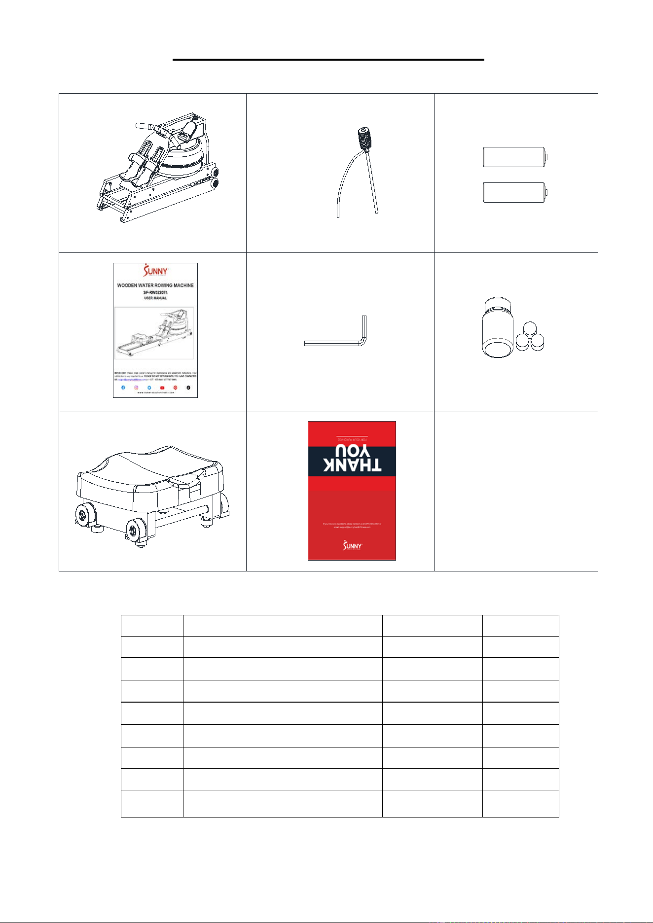
PRE-ASSEMBLY CHECK LIST
A
54
C
D
82
87
50
E
No. Description Spec. Qty.
A
Main Frame 1
54
Pumping Siphon 1
C
Battery AAA 2
D
User Manual 1
82
Allen Wrench 1
87
Water Purification 1
50
Seat 1
E
Thank You Card 1

3
ASSEMBLY INSTRUCTIONS
We value your experience using Sunny Health and Fitness products. For assistance with parts or
troubleshooting, please contact us at support@sunnyhealthfitness.com or 1-877-90SUNNY (877-
907-8669).
12
12
2
3
12
2
4
3
#82 30*80*5 S5 1PC
50
60
60
4
60
4
43
43
2
3
STEP 1:
Take out the Main Frame (No. A) from
the carton and stand the product on its
front end. Lift Rear Connecting Plate
(No. 12) up, shown as Fig A.
Hold on to Rear Connecting Plate (No.
12) and slowly pull the Rear Left Rail
and Rear Right Rail (No. 3 & No. 2)
outward in the direction of arrow to
prevent hand clamping (see Fig B) until
the rower is shown as Fig C.
STEP 2:
Remove the 2 preassembled Seat
Cushion Stops (No. 43) and 2 Screws
(No. 60) at the Rear Left Rail and Rear
Right Rail (No. 3 & No. 2), slide the
Seat (No. 50) into the middle of Rear
Left Rail and Rear Right Rail (No. 3 &
No. 2), and then fix the 2 Seat Cushion
Stops (No. 43) on the Rear Left Rail
and Rear Right Rail (No. 3 & No. 2)
with 2 Screws (No. 60). Tighten with
Allen Wrench (No. 82).
The assembly is complete!
Fig.A
Fig.B
Fig.C
4
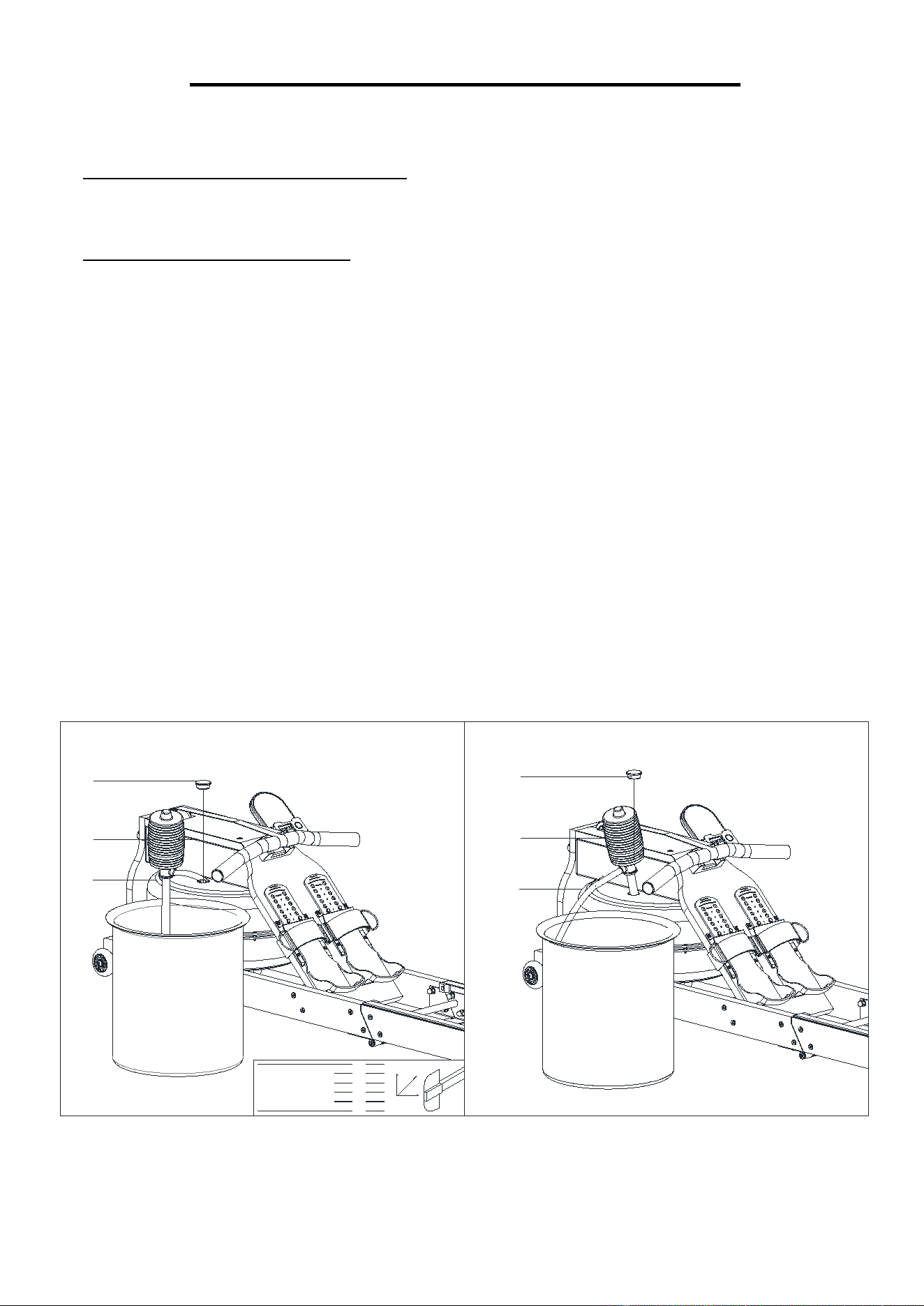
HOW TO FILL AND EMPTY THE TANK
1. Remove the Fill Plug (No. 29) from the Upper Tank Cover (No. 20).
2. To fill the tank with water, refer to Fig. A. Insert the Pumping Siphon (No. 54) into the tank, then
use the Pumping Siphon (No. 54) and a bucket to fill the tank. Use the water level gauge on the
side of the tank to measure desired water level in the tank.
3. To empty the tank, refer to Fig. B. Place a bucket next to the rower, and use the Pumping Siphon
(No. 54) to pump out the water from the tank into the bucket.
4. Insert the Fill Plug (No. 29) into the Upper Tank Cover (No. 20). Wipe excess water off the frame.
NOTE:
• Fill the tank only with tap water. Add 1 water purification tablet (1 packet is included). Never use
pool chlorine or chlorine bleach. This will damage the tank and void the warranty.
• Add a water purification tablet every 6 months or as needed. If water remains cloudy, replace the
water in the tank.
• Do not consume the tank water. Dispose of the water after pumping it out from the tank.
WATER LEVEL
• See Fig. A. The water level gauge is on the side of the tank. The maximum fill level is 6. Never
fill over this limit. Filling the tank over this limit will void the warranty.
• The resistance depends on the water level in the tank. Water level 1 is the lowest resistance.
Level 6 is the highest resistance.
1
2
3
4
5
6
MAX FILL
MIN. FILL
RESIS.
LEVEL
WATER LEVEL
R E S I S T A N C E
54
29
54
29
20
20
Fig.A
Fig.B
5
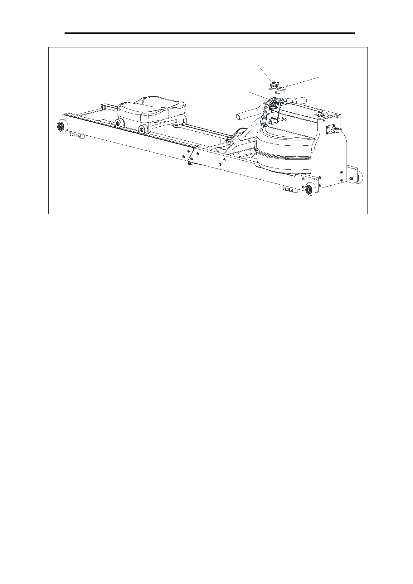
BATTERY INSTALLATION & REPLACEMENT
83
C
83-1
BATTERY INSTALLATION:
1. Take out 2 AAA Batteries from the PE bag.
2. Press down on the buckle of battery cover on the back of the Meter (No. 83), then remove
battery cover.
3. Install 2 AAA Batteries into the battery case on the back of the Meter (No. 83). Pay attention to
the battery + and – poles before installing.
4. Press down on the buckle of battery cover, then put the battery cover back to the back of the
Meter (No. 83).
The installation is complete!
BATTERY REPLACEMENT:
1. Press down on the buckle of battery cover on the back of the Meter (No. 83)
, then remove
battery cover.
2. Remove the 2 old AAA batteries in the battery case and install 2 new AAA batteries into the
battery case on the back of the Meter (No. 83). Pay attention to the battery + and – poles before
installing.
3. Press down on the buckle of battery cover, then put the battery cover back to the back of the
Meter (No. 83).
The replacement is complete!
NOTE: Always change both batteries at the same time. Do not mix battery types and do not mix old
and new batteries. Dispose batteries according to your state and regional guidelines.
6
ADJUSTMENTS GUIDE
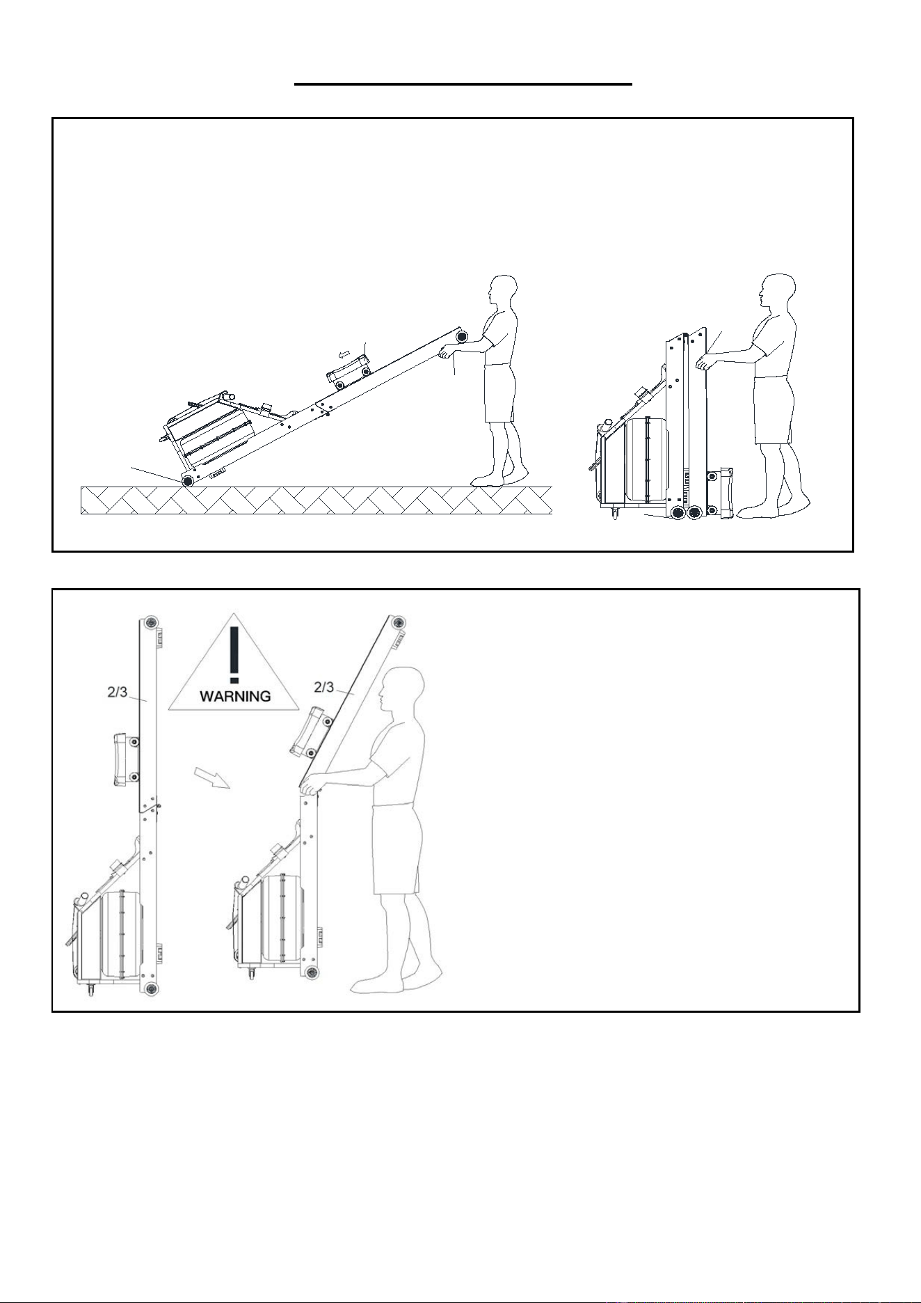
MOVING THE ROWER
To move the rower, lift up the Rail Connecting Plate (No. 4) until the Transportation
Wheels (No. 34) on the front touch the ground. With the Transportation Wheels (No. 34)
on the ground, you can transport the rower to the desired location with ease.
• You can also move the rower by push the Rear Left Rail and Rear Right Rail (No. 3 &
No. 2), when the product is folded.
WARNING! Do not stand the rowing boat or
lift the rail without folding and moving the
rowing boat to prevent the rail or rowing boat
from falling down and hurting people!
34
2/3
B
50
34
2/3
7
ADJUSTMENTS GUIDE
50
4
12
3
12
34
34
35
2
2/3
12
35
2
/3
12
12
34
34
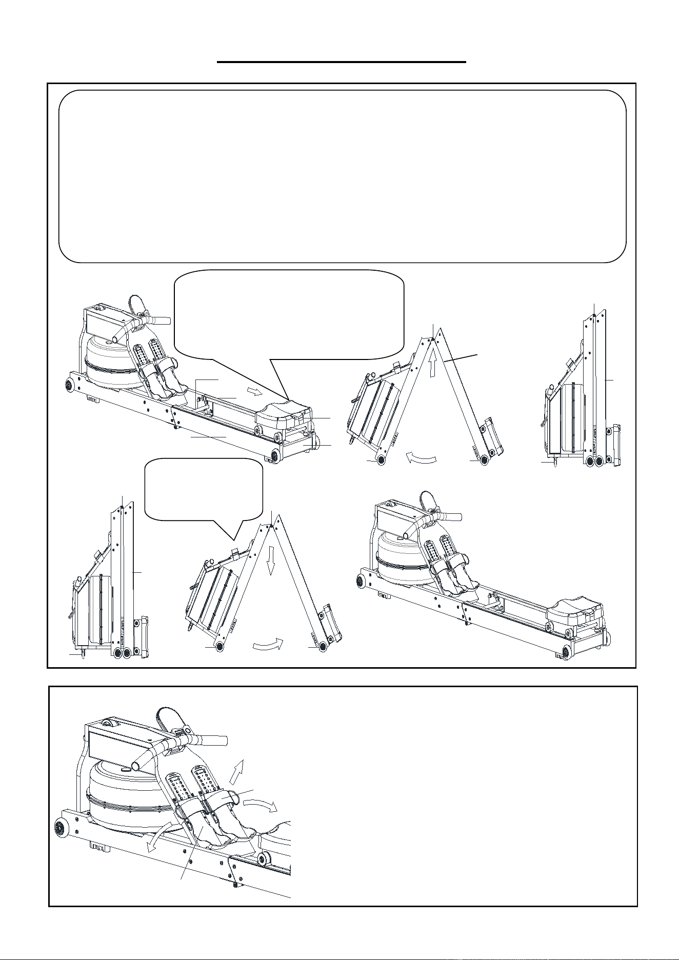
FOLDING OPERATION:
When not in use, you can save space by storing the rower vertically. Hold the Rear Connecting Plate (No. 12) and slowly lift
the Rowing Machine up in the direction of the arrow A to prevent hands from getting caught. Push the Rear Left Rail and Rear
Right Rail (No. 3 & No. 2) in the direction of the arrow B. Press the Universal Wheel (No. 35) brake to fix. (Shown as Fig A)
If not using the rower for more than a month, empty the tank before storing.
UNFOLDING OPERATION:
Hold on Rear Connecting Plate (No. 12) and Rear Left Rail and Rear Right Rail (No. 3 & No. 2), make sure front end of Rower
stays in place. then slowly pull outward in the direction of arrow C to prevent hand clamping. (Shown as Fig B)
CAUTION!
Move the Seat (No. 50) to the end of Rear Left Rail
and Rear Right Rail (No. 3 & No. 2) first or it will
glide down when raising the rower up!
48
33
A
B
B
PEDAL ADJUSTMENT
The Pedal Strap (No. 48) and Adjusting
Pedals (No. 33) is adjustable and can be
personalized to fit the user’s foot size. Secure
your feet firmly to the pedals before using the
rower.
Fig.B
Fig.A
A
B
C
2/3
NOTE: Make sure front
end of Rower stays in
place.
8
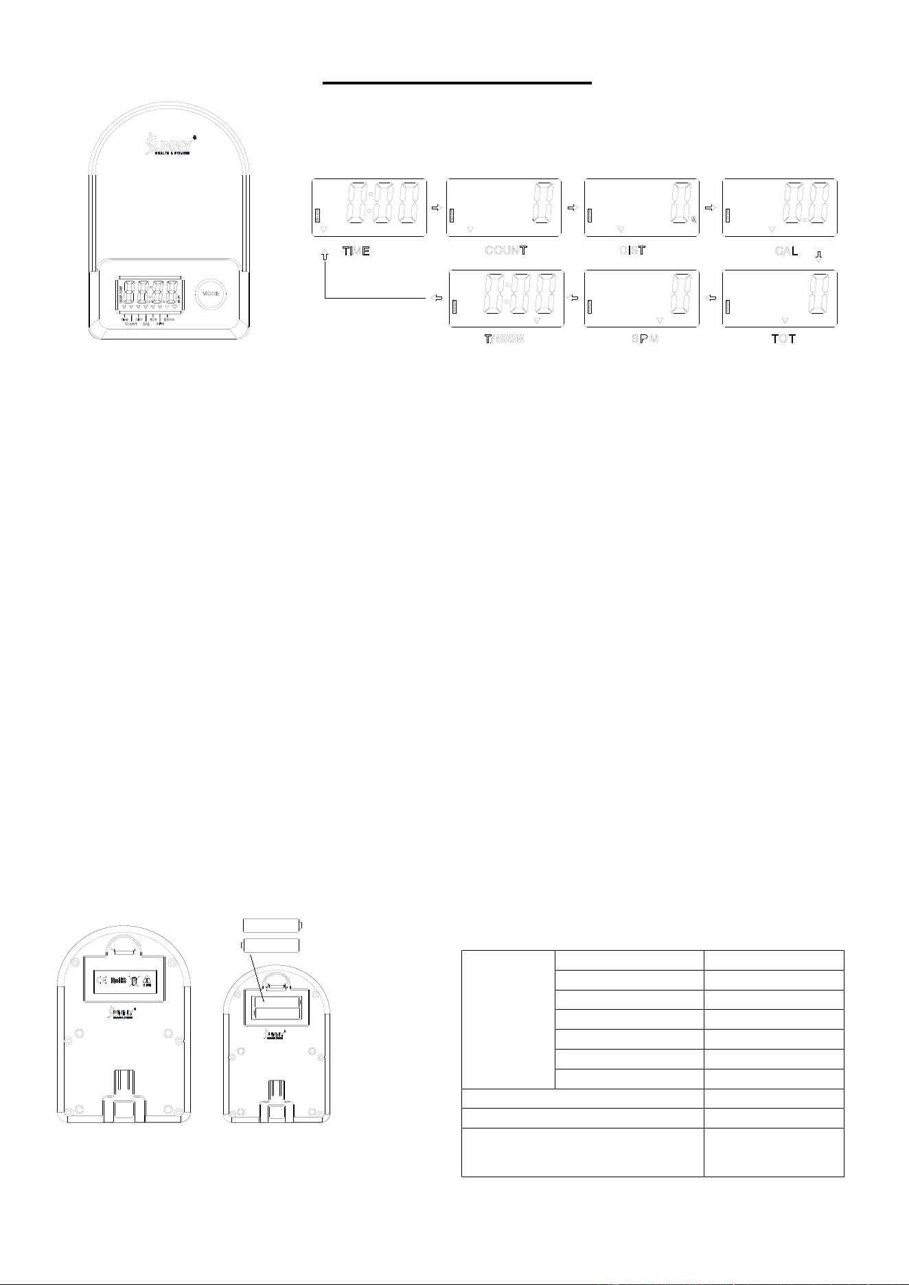
EXERCISE METER
■ KEY FUNCTIONS
:
Pressing the MODE key to select and lock on a function for following sequence:
SCANTIME COUNT DISTANCE (DIST) CALORIES (CAL) TOTAL COUNT (TOT)
SPMT/500M SCAN
Press and hold the MODE key for 3 seconds to reset the value to zero (without TOT).
■ SLEEP MODE:
The system turns on when the MODE key is pressed and system senses a signal input from the
sensor.
The system turns off automatically when the sensor has no signal input or no key pressed for
approximately 4 minutes.
■ FUNCTIONS:
SCAN: Display changes according to the next diagram every 6 seconds.
COUNT: The current count since starting exercise.
DISTANCE (DIST): The current distance since starting exercise.
TIME: The total time since starting exercise.
TOTAL COUNT (TOT): The total count since battery was installed/replaced.
CALORIES (CAL): The calories burned with starting exercise.
SPM: Number of strokes per minute, indicating the stroke speed during exercise.
T/500M: The time for 500 meters during exercise
■ BATTERY INSTALLATION & REPLACEMENT
SPECIFICA
TION
SCAN
6S
TIME
99M:59S
COUNT
0~9999
DISTANCE (DIST)
0~9999 M
TOTAL COUNT (TOT)
0~9999
CALORIES (CAL)
0.0~999.9 KCAL
SPM
0~299
BATTYERY
AAA * 2
OPERATING TEMPERATURE
0~40℃ (32℉-104℉)
STORAGE TEMPERATURE
-10~60℃ (14℉-140℉)

9
APP CONNECTION:
Connect Smart Equipment to SunnyFit App:
1. Scan to download SunnyFit from the app store:
2. Ensure that the Bluetooth function is turned on from your mobile device.
3. If this is your first time using the SunnyFit app, follow the in-app instructions to register for your
free SunnyFit account and log in.
4. Begin any workout activity that matches your smart equipment, then follow the onscreen
prompts to search for and connect to your smart equipment.
5. When connected, your stats and records will be displayed at the end of your course/session,
and recorded in your account profile!
Troubleshooting:
•
If you are having trouble connecting your smart equipment, visit www.sunnyfit.com/guide or
scan the QR code below:
•
If you require additional support, please contact support@sunnyfit.com.
10
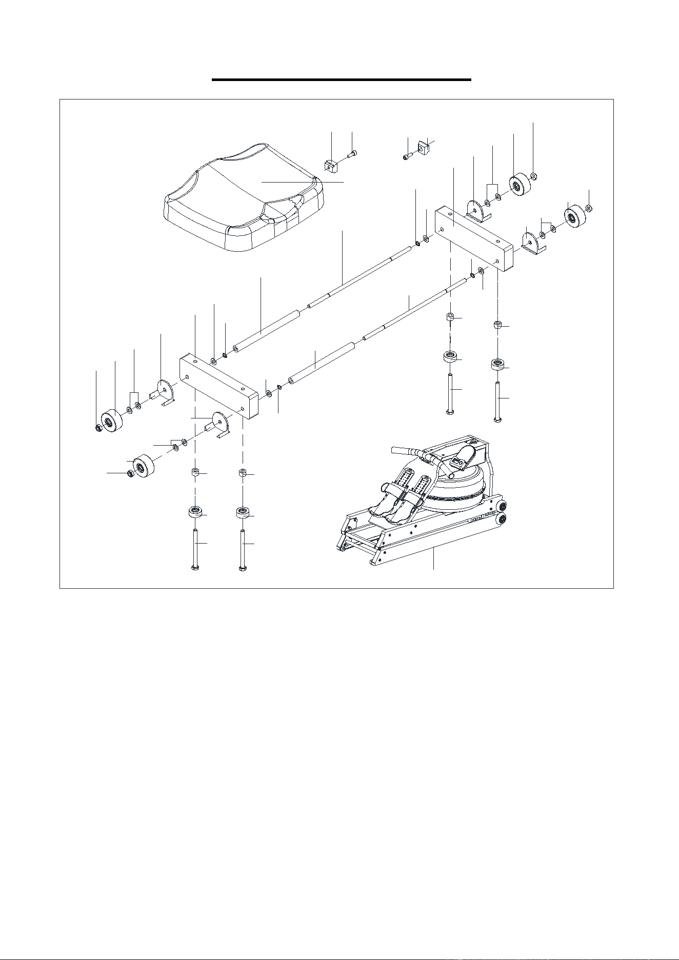
EXPLODED DIAGRAM 1
50
43 60
6043
40
44
68
46
76
79
45
76
46
79
45
5
79
80
39
18
80
79
5
45
79
46
76
76
46
79
45
79
80
18
39
79
80
40
44
68
40
44
68
40
44
68
A
11
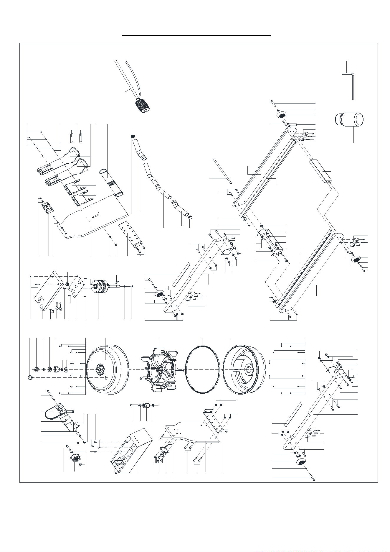
EXPLODED DIAGRAM 2
67
28
13
56
35
57
58
58
6
9
76 76
63
79
34 79
76
51
59
47
1 59 59 55 7955 10 30
76
78
79
30
53 38
85 15 83 65
38
76
25
27
74
29
20
22
23
21
77
56
7
84
55
55
14
71
24
81
70
76 79
59
34 79 63
51
62
42
56
8
55
55
9
69
48
32L/R
33L/R
71
71
47 72
1
59
76
79
78
301130
79
55 59
30
79
79
79 78 78 79
49
43 6059
3
4
647934
79
57
72 47
72 47 79 34 79 64
2
49
60
43 59
30
17
57
72
41
36
37L
16
37R
36
54
82
12
19
66
86
31
86
52
61
73
86
87
75
78
26
88
27
26
Version 1.2

12
PARTS LIST
No. Description Spec. Qty. No.
Description
Spec.
Qty.
1 Front Rail 867*80*27 2 45 Roller Positioning Seat PVC/46*43.5*32.4 4
2 Rear Right Rail 960*80*27 1 46 Seat Roller TPU+608/Ø46*22 4
3 Rear Left Rail 960*80*27 1 47 Foot Pad PVC/100*25*25 4
4 Rail Connecting Plate 260*55*27 1 48 Pedal Strap PP+D/50*1.5*1083 1
5 Seat Carriage 220*60*27 2 49 Sidebar PVC/30*17.5*952 2
6 Front Bezel 373*240*20 1 50 Seat PU/320*260*52 1
7 Top Connecting Plate 343*152*20 1 51
EVA Pad EVA/25*300*δ2 2
8 Pedal Plate 490*250*20 1 52
EVA Pad EVA/90*25*δ2
2
9 Connecting U-plate 260*70*40 2 53 Wire Plug Ø14.5*Ø12*Ø4*12 1
10 Left Front Connecting Plate 90*85*30 1 54 Pumping Siphon PE/570 1
11 Right Front connecting Plate 90*85*30 1 55 Screw M6*15*S4 8
12 Rear Connecting Plate 260*85*75.2 1 56 Screw M6*30*S4 8
13 Water Tank Fixing Seat 1 57 Screw M6*50*S4 4
14 Fixed Plate Q235/170*116*2 1 58 Screw M8*32*S5 4
15 Meter Support Plate 1 59 Screw M8*40*15*S5 16
16 Handlebar Q235/Ø28*1.5*434 1 60 Screw M6*16*S5 4
17 Long Shaft Q235/Ø10*305 1 61 Screw
M6*15*S5 4
18 Seat Roller Shaft Q235/Ø8*320 2 62 Screw
M6*32*S4
2
19 Fixing Pin SUS304/Ø10*40 1 63 Screw M8*65*20*S5 2
20 Upper Tank Cover Ø440*100 1 64 Screw M8*80*20*S5 2
21 Lower Tank Cover Ø440*100 1 65 Screw M8*110*30*S6 1
22 Impeller Ø390*145 1 66 Screw M10*50*15*S6 1
23 Rubber Sealing Ring Ø430*7 1 67 Screw M10*55*S6 1
24 Pullback Device 1 68 Bolt M8*90*20*S14 4
25 Plastic Bearing Seat PP/Ø60*Ø45*30 1 69 Screw M6*15*S10 3
26 Rubber Washer Ø40*7 2 70 Screw M8*20*S5 1
27 TC Framework Oil Seal NBR/Ø20*Ø40*8 2 71 Screw
ST4.2*16*Ф7 10
28 Plastic Pulley POM/Ø68*Ø54*32 1 72 Screw
ST4.2*19*Ф11
12
29 Fill Plug Ø31.3*10.4 1 73 Screw M4*6*Ø7 2
30 Plastic Shaft Sleeve PP/Ø18*Ø10.2*13 6 74 Screw M3*17*Ø6 12
31 Small Webbing Pulley POM/Ø51*Ø38*32 1 75 Nylon Lock Nut M10*H12*S17 1
32L/R Foot Pedal PP/132*106*18 1pr. 76 Nylon Lock Nut M8*H7.5*S13 19
33L/R Adjusting Pedal PP/343*106*56 1pr. 77 Nylon Lock Nut M3*H3.8*S6 12
34 Transportation Wheel PU+608 Ø69*23.5 4 78 Cap Nut M8*H16*S13 8
35 Universal Wheel PU/Ø40 1 79 Washer D8*Ø16*1.5 34
36 Handlebar Cap PP/Ø28*1.5 2 80 Shaft Ring D8*0.8 4
37L/R Handlebar Sleeve Ø27*Ø33*210 1pr. 81 Washer D8*Ø16*1.5 1
38 PVC Sleeve PVC/Ø15*Ø8.2*40 2 82 Allen wrench 30*80*5 S5 1
39 PVC Sleeve 2 PVC/Ø15*Ø8.2*195 2 83 Meter 521020 (HT087) 1
40 PVC Sleeve 3 PVC/Ø15*Ø8.2*10 4 84 Sensor Wire L200mm 2
41 Spindle Sleeve Nylon/Ø30*Ø17*15 1 85 Screw M5*10 4
42 Handle Holder ABS/96*54*40 1 86 Washer D10*Ø14*1 4
43 Seat Cushion Stop PVC/25*15*10 4 87 Water Purification Ø30*30 1
44 Small Roller TPU+608/Ø28*11.5 4 88 Bearing 6904 1
A Main Frame 1

13