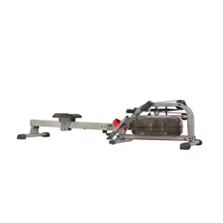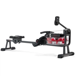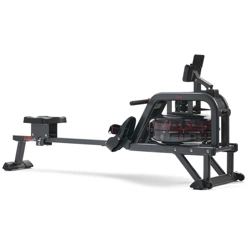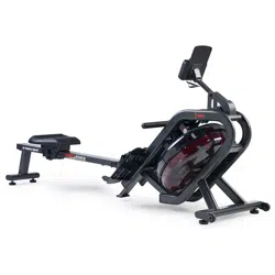
PHANTOM HYDRO SMART
WATER ROWING MACHINE
SF-RW5910 SMART
USER MANUAL
IMPORTANT! Please retain owner’s manual for maintenance and adjustment instructions. Your
satisfaction is very important to us, PLEASE DO NOT RETURN UNTIL YOU HAVE CONTACTED
US: [email protected] or 1-877-90SUNNY (877-907-8669).

1
IMPORTANT SAFETY INFORMATION
We thank you for choosing our product. To ensure your safety and health, please use this
equipment correctly. It is important to read this entire manual before assembling and using
the equipment. Safe and effective use can only be achieved if the equipment is assembled,
maintain and used properly. It is your responsibility to ensure that all users of the equipment
are informed of all warnings and precautions.
1. Before starting any exercise program, you should consult your physician to determine if
you have any medical or physical conditions that could put your health and safety at risk
or prevent you from using the equipment properly. Your physician’s advice is essential if
you are taking medication that affects your heart rate, blood pressure or cholesterol
level.
2. Be aware of your body’s signals. Incorrect or excessive exercise can damage your
health. Stop exercising if you experience any of the following symptoms: pain, tightness
in your chest, irregular heartbeat, shortness of breath, lightheadedness, dizziness or
feelings of nausea. If you do experience any of these conditions, you should consult
your physician before continuing with your exercise program.
3. Keep children and pets away from the equipment. The equipment is designed for adult
use only.
4. Use the equipment on a solid, flat level surface with a protective cover for your floor or
carpet. To ensure safety, the equipment should have at least 2 feet (60 cm) of free space
all around it.
5. Ensure that all nuts and bolts are securely tightened before using the equipment. The
safety of the equipment can only be maintained if it is regularly examined for damage
and/or wear and tear.
6. Always use the equipment as indicated. If you find any defective components while
assembling or checking the equipment, or if you hear any unusual noises coming from
the equipment during exercise, discontinue use of the equipment immediately and do
not use until the problem has been rectified.
7. Wear suitable clothing while using the equipment. Avoid wearing loose clothing that may
become entangled in the equipment.
8. Do not place fingers or objects into the moving parts of the equipment.
9. The maximum weight capacity of this unit is 300 lbs (135 kgs).
10. The equipment is not suitable for therapeutic use.
11. To avoid bodily injury and/or damage to the product or property, proper lifting and
moving is required.
12. Your product is intended for use in cool and dry conditions. You should avoid storage in
extreme cold, hot or damp areas as this may lead to corrosion and other related
problems.
13. This equipment is designed for indoor and home use only. It is not intended for
commercial use.
2
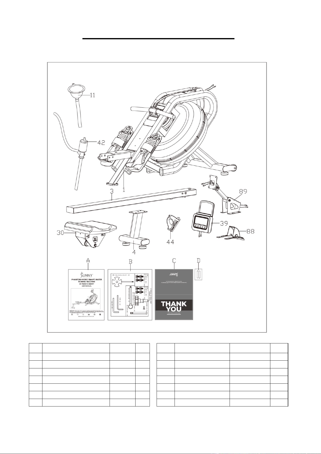
PRE-ASSEMBLY CHECK LIST
Before you start to assemble, please make sure all parts are included.
No.
Description
Spec.
Qty.
No.
Description
Spec.
Qty.
1
Main Frame
1
44
Bottle Holder
1
3
Slide Rail
1
88
Protective Cover
1
4
Rear Support Tube
1
89
Fixed Plate
1
11
Funnel
1
A
Manual
1
30
Seat
1
B
Hardware Package
1
39
Meter
HT109
1
C
Thank You Card
1
42
Pumping Siphon
1
D
Battery
AA
2
3
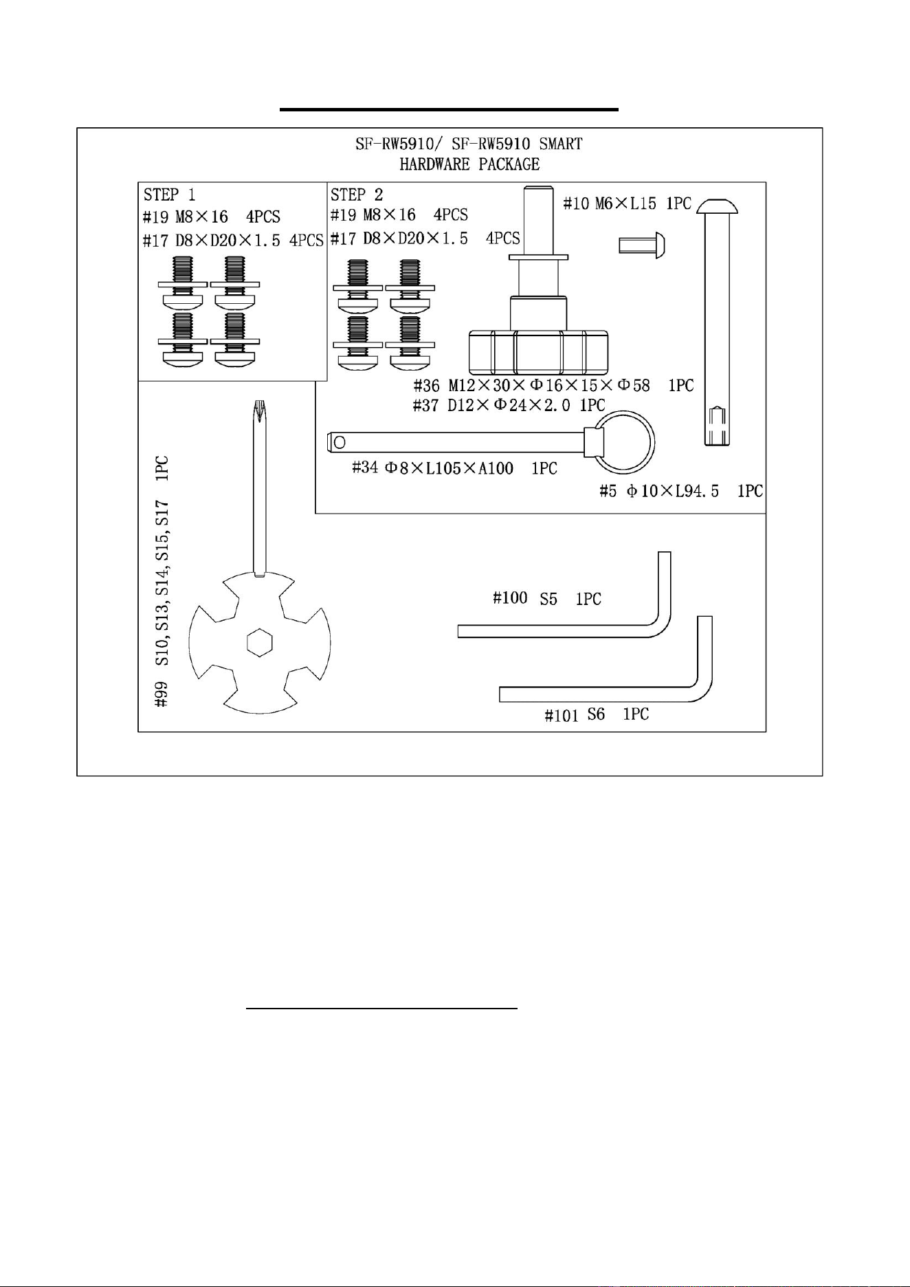
HARDWARE PACKAGE
Ordering Replacement Parts (U.S. and Canadian Customers only)
Please provide the following information in order for us to accurately identify the part(s)
needed:
✓ The model number (found on cover of manual)
✓ The product name (found on cover of manual)
✓ The part number found on the “EXPLODED DIAGRAM” (pages 15~16) and “PARTS
LIST” (pages 17~18)
Please contact us at [email protected] or 1-877-90SUNNY (877-907-8669).
4
ASSEMBLY INSTRUCTIONS
We value your experience using Sunny Health and Fitness products. For assistance with parts or
troubleshooting, please contact us at suppo[email protected] or 1-877-90SUNNY (877-
907-8669).
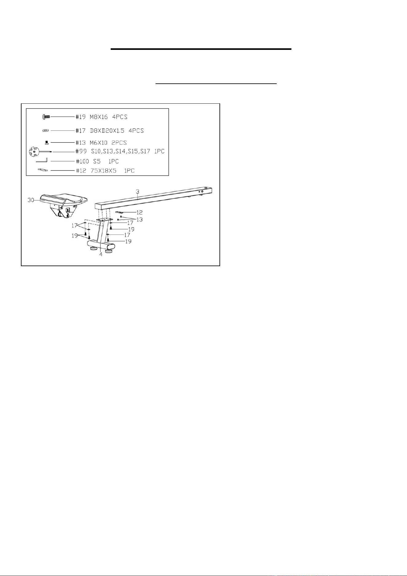
STEP 1:
Remove the pre-assembled Limit
Cushion (No. 12) and 2 Screws (No. 13)
from the Slide Rail (No. 3) using
Spanner (No. 99).
Slide the Seat (No. 30) on to the Slide
Rail (No. 3), make sure Seat (No. 30) is
through the position of the Limit Cushion
(No. 12). Then attach the Limit Cushion
(No. 12) to the Slide Rail (No. 3) with 2
Screws (No. 13) that were just removed.
Tighten and secure with Spanner (No.
99).
Attach the Rear Support Tube (No. 4) to
the Slide Rail (No. 3) with 4 Screws (No.
19) and 4 Flat Washers (No. 17). Tighten
and secure with Allen Wrench (No. 100).
5
We value your experience using Sunny Health and Fitness products. For assistance with parts or
troubleshooting, please contact us at suppo[email protected] or 1-877-90SUNNY (877-
907-8669).
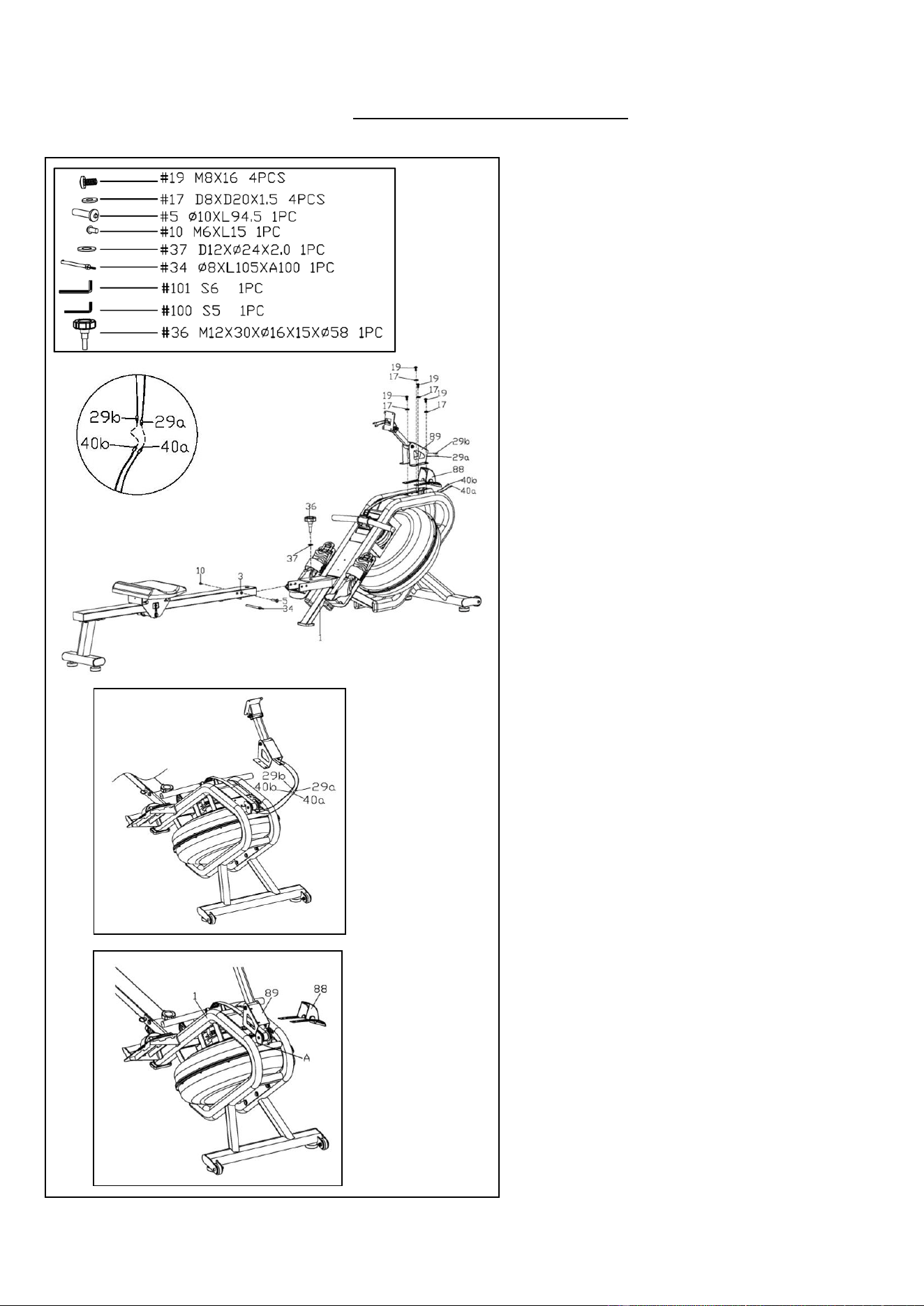
STEP 2:
Attach the Slide Rail (No. 3) to the Main
Frame (No. 1) with Bolt (No. 5) and Bolt
(No. 10) by using Allen Wrenches (No.
101 & No. 100). Then tighten with Knob
(No. 36) and Flat Washer (No. 37), and
finally insert Pull Pin (No. 34).
Connect Sensor Wire A (No. 40a) with
Extension Wire A (No. 29a) and connect
Sensor Wire B (No. 40b) with
Extension Wire B (No. 29b).
After connecting the Sensor Wires A &
B (No. 40a & No. 40b) with Extension
Wires A & B (No. 29a & No. 29b). The
wires will be exposed. (Fig. A)
Move all wires to the side of plate A. (Fig.
B)
Attach the Protective Cover (No. 88)
and Fixed Plate (No. 89) to the Main
Frame (No. 1) with 4 Screws (No. 19)
and 4 Flat Washers (No. 17). Tighten
and secure with Allen Wrench (No. 100).
NOTE: Be careful not cut any wires when
attaching the Protective Cover (No. 88)
and Fixed Plate (No. 89) to the Main
Frame (No. 1).
Fig. A
Fig. B
6
We value your experience using Sunny Health and Fitness products. For assistance with parts or
troubleshooting, please contact us at suppo[email protected] or 1-877-90SUNNY (877-
907-8669).
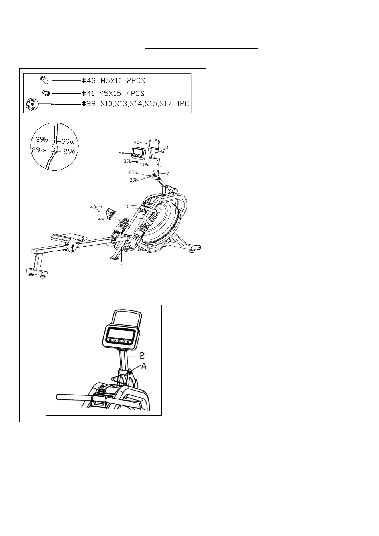
STEP 3:
Remove the pre-assembled 2 Screws
(No. 43) from the Main Frame (No. 1)
using Spanner (No. 99). Attach the
Bottle Holder (No. 44) to the Main
Frame (No. 1) with 2 Screws (No. 43)
that were just removed. Tighten and
secure with Spanner (No. 99).
Remove the pre-assembled 4 Screws
(No. 41) from the back of Tablet Holder
(No. 45) using Spanner (No. 99).
Connect Extension Wire A (No. 29a)
with Meter Wire A (No. 39a) and
connect Extension Wire B (No. 29b)
with Meter Wire B (No. 39b). Then
attach the Meter (No. 39) and the
Tablet Holder (No. 45) to the Meter
Plate (No. 7) with 4 Screws (No. 41)
that were just removed. Tighten and
secure with Spanner (No. 99).
NOTE: Put all wires into the Meter
Support Tube (No. 2) before attaching
the Meter (No. 39) and the Tablet
Holder (No. 45) to Main Frame (No. 1).
If there are wires exposed from the
bottom hole “A” of the Meter Support
Tube (No. 2). Push all wires up into the
Meter Support Tube (No. 2). (Fig. A)
The assembly is complete!
Fig. A
7
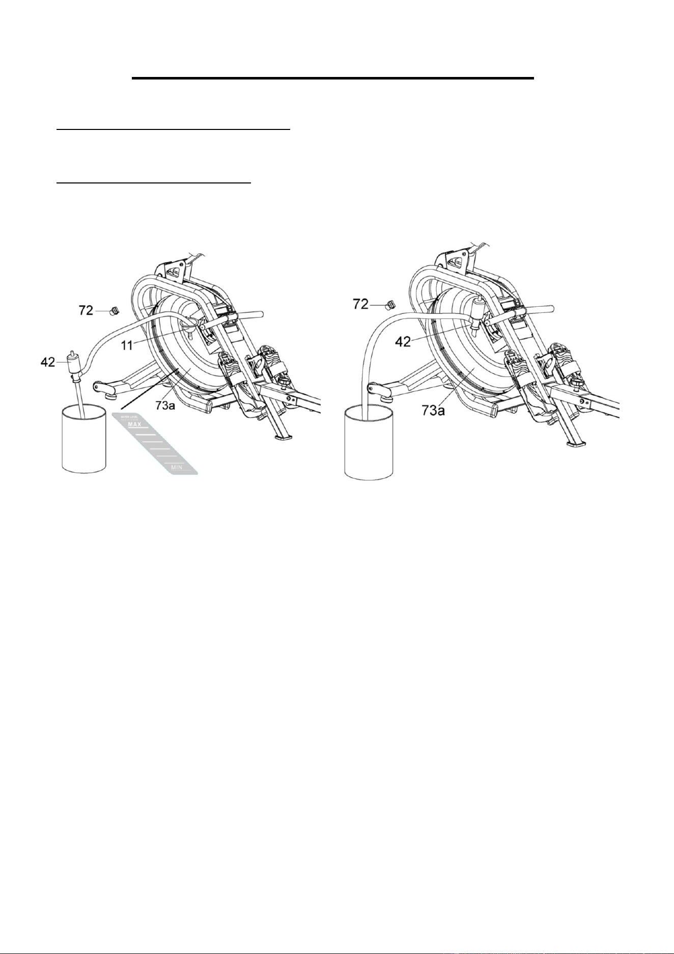
HOW TO FILL AND EMPTY THE TANK
1. Remove the Plug (No. 72) from the Upper Tank Cover (No. 73a).
2. To fill the tank with water, refer to Fig. A. Insert the Funnel (No. 11) into the tank, then use a
bucket and Pumping Siphon (No. 42) to fill the tank. Use the water level gauge on the side of
the tank to measure desired water level.
3. To empty the tank, refer to Fig. B. Place a bucket next to the rower and use the Pumping
Siphon (No. 42) to pump the water out from the tank into the bucket.
4. Insert the Plug (No. 72) back into the Upper Tank Cover (No. 73a). Wipe off excess water
around the area.
NOTE:
• Fill the tank only with tap water. Add 1 water purification tablet (1 packet is included). Never
use pool chlorine or chlorine bleach. This will damage the tank and void the warranty.
• Add a water purification tablet every 6 months or as needed. If the water remains cloudy,
replace the water in the tank.
• Do not consume the tank water. Dispose of the water after pumping it out from the tank.
WATER LEVEL
• The water level gauge is on the side of the tank. There is a max level. Never fill over this limit.
Filling the tank over this limit will void the warranty.
• The resistance depends on the water level in the tank. The min level is the lowest resistance.
The max level is the highest resistance.
Fig. A
Fig. B
8
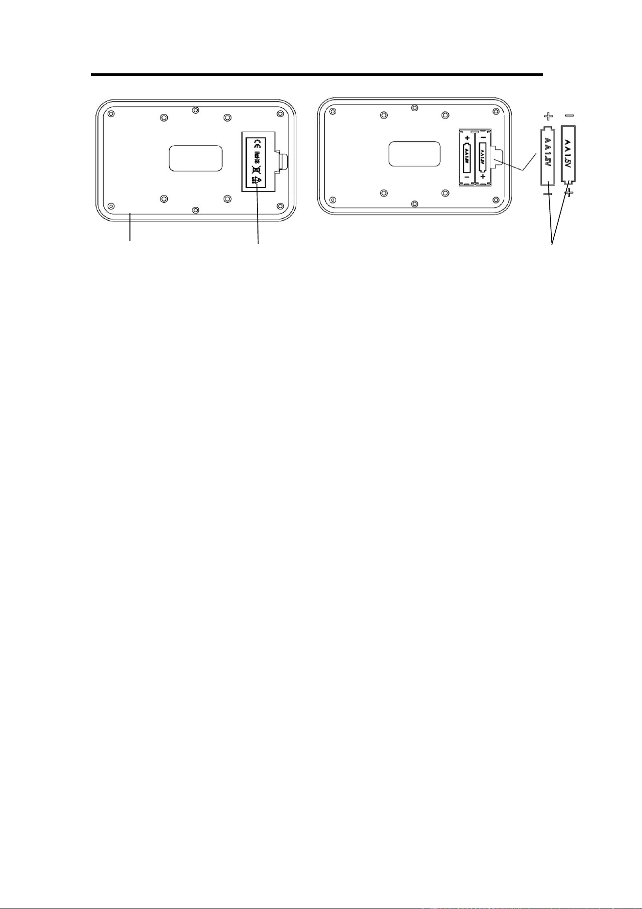
BATTERY INSTALLATION & REPLACEMENT
BATTERY INSTALLATION:
1. Take out 2 AA batteries from meter box.
2. Press the buckle of battery cover on the back of the Meter (No. 39), then remove battery
cover.
3. Install 2 AA batteries into the battery case on the back of the Meter (No. 39). Pay
attention to the battery + and – poles before installing.
4. Press the buckle of battery cover, then put the battery cover back to the back of the
Meter (No. 39).
The installation is complete!
BATTERY REPLACEMENT:
1. Press the buckle of battery cover on the back of the Meter (No. 39), then remove battery
cover.
2. Remove the 2 old AA batteries in the battery case and install 2 new AA batteries into the
battery case on the back of the Meter (No. 39). Pay attention to the battery + and – poles
before installing.
3. Press the buckle of battery cover, then put the battery cover back to the back of the
Meter (No. 39).
The replacement is complete!
NOTE: Always change both batteries at the same time. Do not mix battery types and do not
mix old and new batteries. Dispose batteries according to your state and regional guidelines.
39
Battery Cover
Battery
9
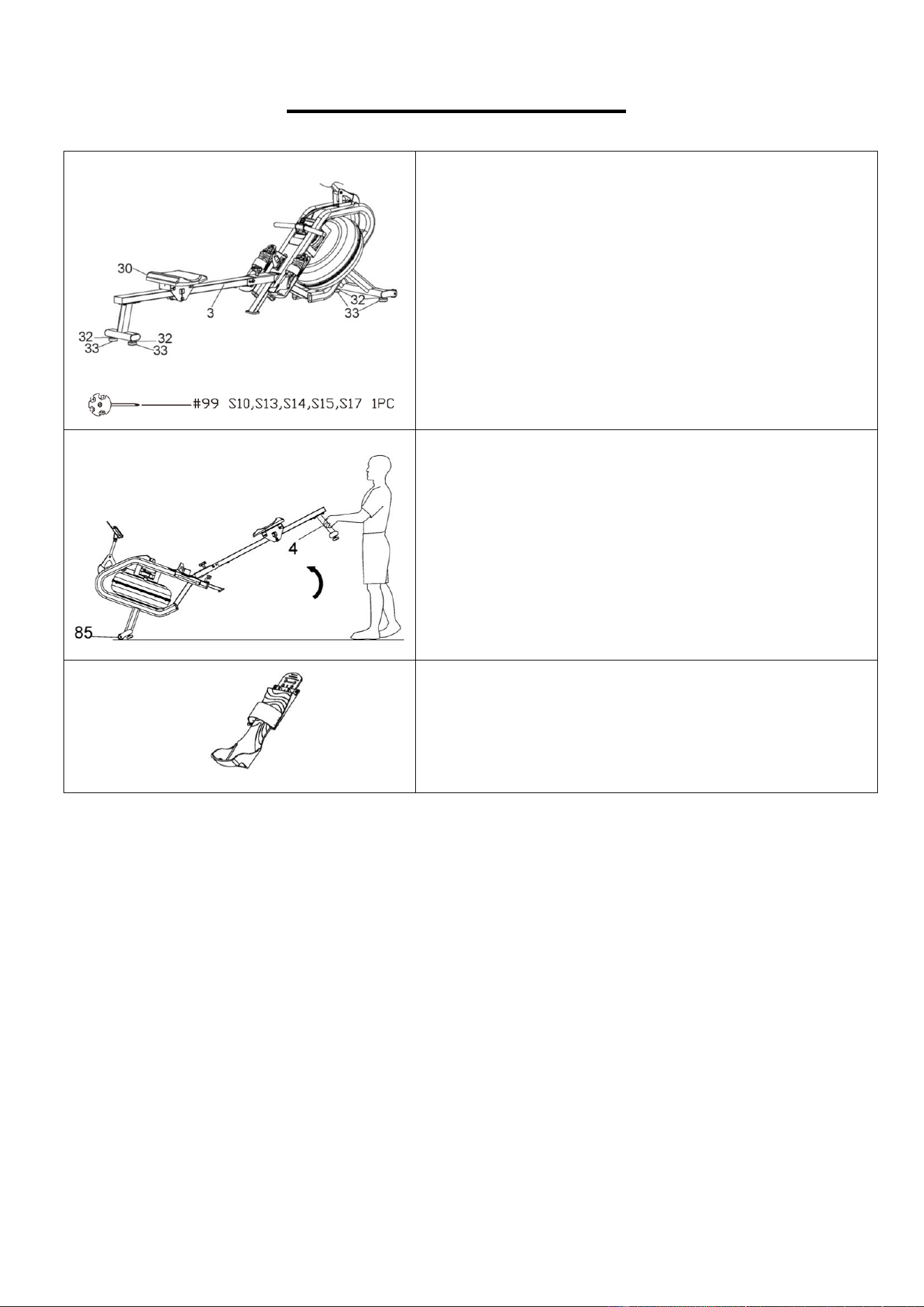
ADJUSTMENTS GUIDE
ADJUSTING THE BALANCE
If the rower is unbalanced during use, adjust the Hex
Nuts (No. 32) on the Adjustable Foot Pads (No. 33)
of the rower using Spanner (No. 99).
CAUTION!
Moving parts, such as the Seat (No. 30), can crush or
cut. Keep hands clear of the Slide Rail (No. 3) during
use!
MOVING THE ROWER
To move the rower, lift up the Rear Support Tube
(No. 4) until the Transportation Wheels (No. 85)
touch the ground. With the Transportation Wheels
(No. 85) on the ground, you can transport the rower
to the desired location with ease.
PEDAL ADJUSTMENT
The pedal strap is adjustable and can be personalized
to fit the user’s foot size.
10
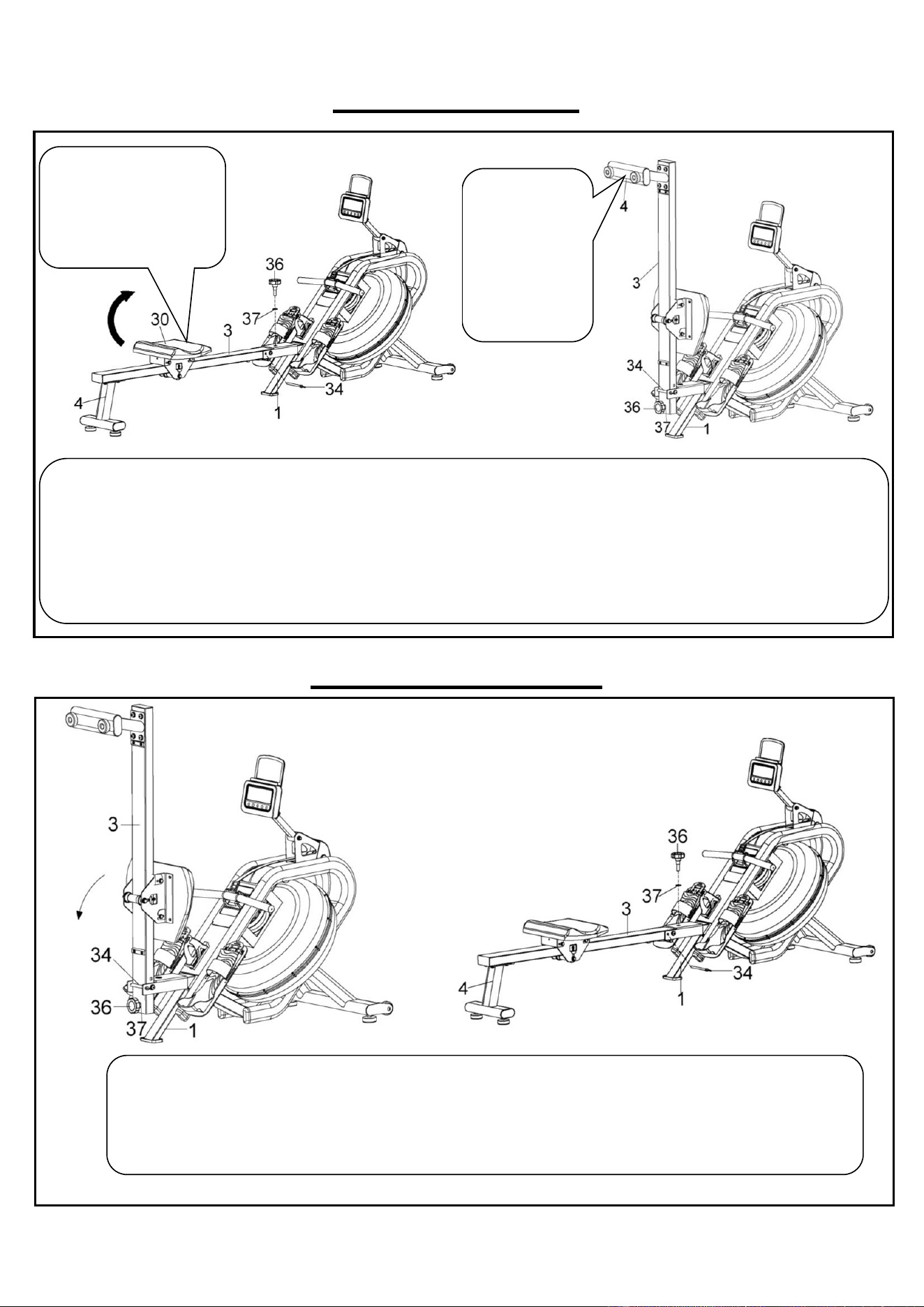
FOLDING GUIDE
UNFOLDING GUIDE
When not in use, you can save space by folding the Slide Rail (No. 3).
Unscrew the Knob (No. 36) and Flat Washer (No. 37), and remove the Pull Pin (No. 34) from Main Frame (No. 1)
(Fig. A). Lower the Seat (No. 30) all the way down. Then fold the Slide Rail (No. 3) up.
CAUTION: The Seat (No. 30) will slide down when folding the Slide Rail (No. 3).
Insert Knob (No. 36) and Flat Washer (No. 37) into the holes in the back of the Slide Rail (No. 3) and tighten. Then
insert Pull Pin (No. 34) into the Main Frame (No. 1) (Fig. B).
If not using the rower for more than a month, empty the tank before storing.
To unfold the Slide Rail (No. 3), first remove Knob (No. 36) and Flat Washer (No. 37) from the Slide Rail
(No. 3) and remove Pull Pin (No. 34) from Main Frame (No. 1). (Fig. A)
Slowly fold down the Slide Rail (No. 3), then screw Knob (No. 36) and Flat Washer (No. 37) into Main
Frame (No. 1) and insert Pull Pin (No. 34) into Main Frame (No. 1). (Fig. B)
CAUTION: When unfolding, please use one hand to hold the Slide Rail (No. 3) to avoid injury.
Fig. B
CAUTION!
Move with
caution when
you raise the
rower up, as
your head may
touch the Rear
Support Tube
(No. 4).
Fig. A
CAUTION!
Move the Seat (No. 30)
to the front of Slide Rail
(No. 3) first or it will
glide down when raising
the rower up!
Fig. A
Fig. B
11
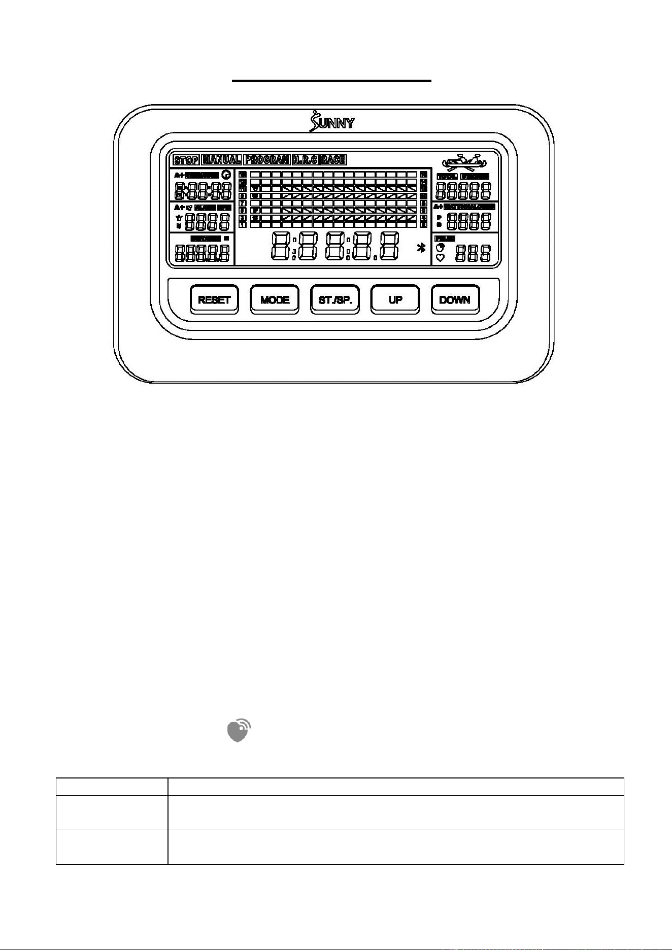
EXERCISE METER
⚫ TIME, TIME/500, SPM, DISTANCE, STROKES, TOTAL STROKES, CALORIES, WATT,
PULSE.
FUNCTION
⚫ TIME: The total working time since starting exercise. Display range: 0:00:00 ~ 9:59:59
(H:M:S).
⚫ TIME/500: The average time for 500 meters during exercise. Display range: 0:00 ~
99:59 (M:S).
⚫ SPM: Number of strokes per minute, indicating the stroke speed during exercise.
Display range: 0 ~ 240.
⚫ STROKES: The current count since starting exercise. Display range: 0 ~ 99999.
⚫ DISTANCE: The current distance since starting exercise. Display range: 0 ~ 99999
meters.
⚫ CALORIES: The current calories burned since starting exercise. Display range: 0 ~
9999 Cal.
⚫ TOTAL STROKES: The total strokes with all of the workout since starting exercise. If the
batteries are replaced, the value resets to zero. Display range: 0 ~ 99999.
⚫ WATTS: Display the user’s exercise power.
⚫ PULSE: Display the real time pulse, when the heart rate monitor is connected, the
wireless heart rate icon is on.
EXERCISE MODE
MANUAL
Standard exercise mode.
PROGRAM
TIME/DISTANCE/DISTANCE/STROKES countdown mode, and PULSE
warning mode.
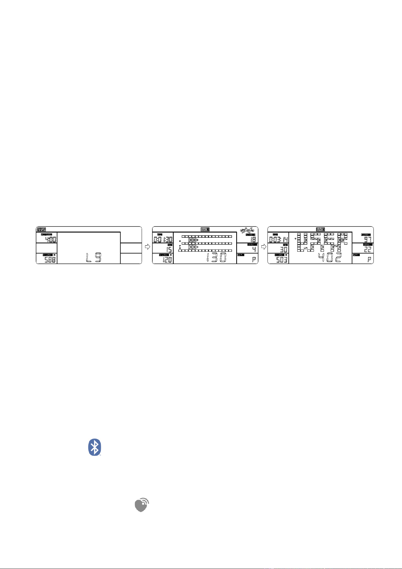
RACE
Race mode. User-defined PC difficulty (L1-L15), you can choose the
distance to race: 500-10000 meters.
12
KEY FUNCTION
UP
1. Select exercise mode upwards.
2. Increase the value during setting.
DOWN
1. Select exercise mode downwards.
2. Decrease the value during setting.
MODE
1. During exercise, switch the display: TIME or TIME/500, STROKES
or TOTAL STROKES, CALORIES or WATT.
2. In PROGRAM mode or RACE mode, select and fix a function to
set.
RESET
1. Return to the initial interface in stop state.
2. Reset the setting values to 0 when Bluetooth is not connected.
3. Press and hold the key for 2 seconds to clear all the function values
during exercise when Bluetooth is not connected.
4. Press and hold the key for 6 seconds to disconnect from both the
SunnyFit APP and the heart rate monitor; then, the meter will enter
sleep mode.
ST./SP.
(START/STOP)
1. Enter the exercise mode.
2. Start or stop exercise.
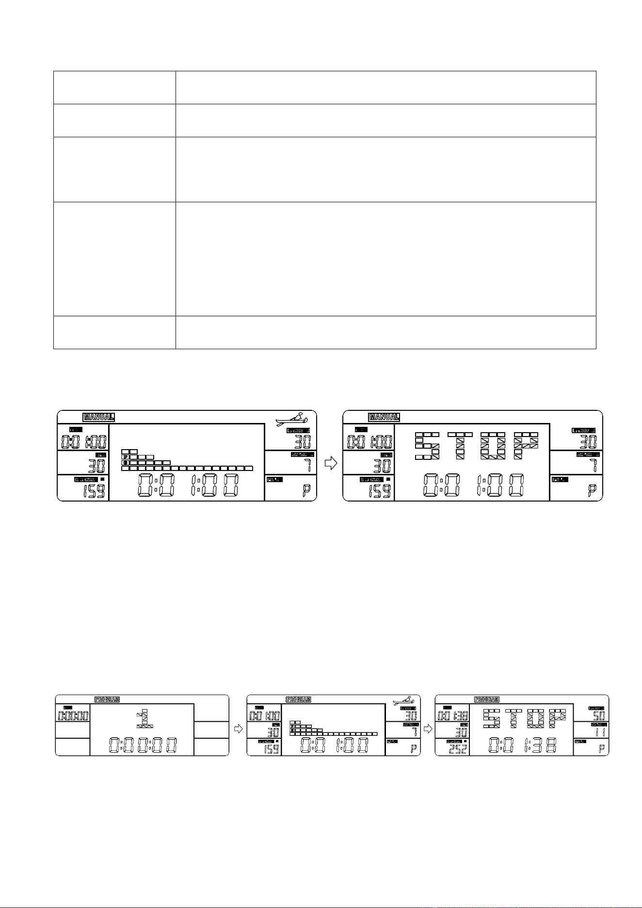
MANUAL MODE
⚫ Press UP or Down key to select and lock onto “MANUAL”.
⚫ Press ST./SP. key to start exercise.
⚫ Press UP or DOWN key to select a particular function value to display in main window.
⚫ Press MODE key to select and fix a function to display: TIME, STROKES, CALORIES
or TIME/500, TOTAL STROKES, WATT.
⚫ When in stop state, press ST./SP. key to restart; when in exercise state; press the
ST./SP. key to stop.
⚫ Press RESET key to return to the initial interface in stop state.
PROGRAM MODE
⚫ Press UP or Down key to select and lock onto “PROGRAM”.
⚫ Press ST./SP. key to set the mode.
⚫ Press MODE key to select a function to set: TIME→DISTANCE→STROKES
→CALORIES→PULSE.
13
⚫ Press UP or DOWN keys to increase or decrease the setting value. Press RESET key to
reset the setting value to 0.
⚫ Press ST./SP. key to start exercise.
⚫ Press UP or DOWN key to select a particular function value to display in main window.
⚫ Press MODE key to select and fix a function to display: TIME or TIME/500, STROKES or
TOTAL STROKES, CALORIES or WATT.
⚫ If any function is set, at exercise state, this function is displayed as a countdown (except
PULSE). When the countdown reaches 0, the exercise will automatically stop with a "DI
DI" sound prompt.
⚫ If PULSE value is set, at exercise state, when your pulse value surpasses the target
value, the exercise will automatically stop with a "DI DI" sound prompt.
⚫ When in stop state, press ST./SP. key to restart; when in exercise state; press the
ST./SP. key to stop.
⚫ Press RESET key to return to the initial interface in stop state.
NOTE: If more than one function value is set, only the last function value is valid.
RACE MODE
⚫ Press UP or Down key to select and lock onto “RACE”.
⚫ Press ST./SP. key to set the mode.
⚫ Press MODE key to select the function to set: TIME/500 or DISTANCE.
⚫ Press UP or DOWN key to increase or decrease the setting value.
⚫ PC level of difficulty is L1-L15. At higher difficulty, the PC will finish the race faster.
⚫ Press ST./SP. key to start exercise.
⚫ The one who finishes the race first is the winner.
⚫ When in stop state, press ST./SP. key to restart; when in exercise state; press the
ST./SP. key to stop.
⚫ Press RESET key to return to the initial interface in stop state.
■SLEEP MODE
⚫ The system turns off automatically and disconnects the heart rate monitor if the sensor
has no signal input, or no key are pressed for approximately 4 minutes when Bluetooth
is not connected.
⚫ The system turns on when any key is pressed or there is a signal input.
BLUETOOTH :
1. The Bluetooth icon will flash when the meter is on or wakes from sleep mode. If no
Bluetooth connection is established within 3 minutes, the Bluetooth icon will turn off.
2. The Bluetooth icon will stay on when it is connected.
WIRELESS HEART RATE :
1. The wireless heart rate icon will flash when the meter is on. If the heart rate monitor is not

14
connected within 1 minute, the wireless heart rate icon will turn off.
2. After exercise resumes, the wireless heart rate icon will flash. If the heart rate monitor is
not connected within 1 minute, the wireless heart rate icon will turn off.
3. When the meter wakes from sleep mode, the wireless heart rate icon will flash. If the
heart rate monitor is not connected within 1 minute, the wireless heart rate icon will turn
off.
4. The wireless heart rate icon will flash when the MODE key is pressed. If the heart rate
monitor is not connected within 1 minute, the wireless heart rate icon will turn off.
5. The wireless heart rate icon will stay on when the heart rate monitor is connected.
NOTE: The heart rate monitor is not included. Wireless heart rate function works with
SunnyFit Heart Rate Monitor HR200.
BATTERY
This meter uses 2 AA batteries, which are included. Changing the batteries will reset all
values. If there is a problem with the display, try to change the batteries first. When
changing the batteries, change both at the same time. Do not mix battery types. Do not mix
old and new batteries. Dispose of old batteries according to your regional guidelines.
APP CONNECTION:
Connect Smart Equipment to SunnyFit App:
1. Scan to download SunnyFit from the app store:
2. Ensure that the Bluetooth function is turned on from your mobile device.
3. If this is your first time using the SunnyFit app, follow the in-app instructions to
register for your free SunnyFit account and log in.
4. Begin any workout activity that matches your smart equipment, then follow the
onscreen prompts to search for and connect to your smart equipment.
5. When connected, your stats and records will be displayed at the end of your
course/session and recorded in your account profile!
Troubleshooting:
•
If you are having trouble connecting your smart equipment, visit
www.sunnyfit.com/guide or scan the QR code below:
•
If you require additional support, please contact [email protected].
15
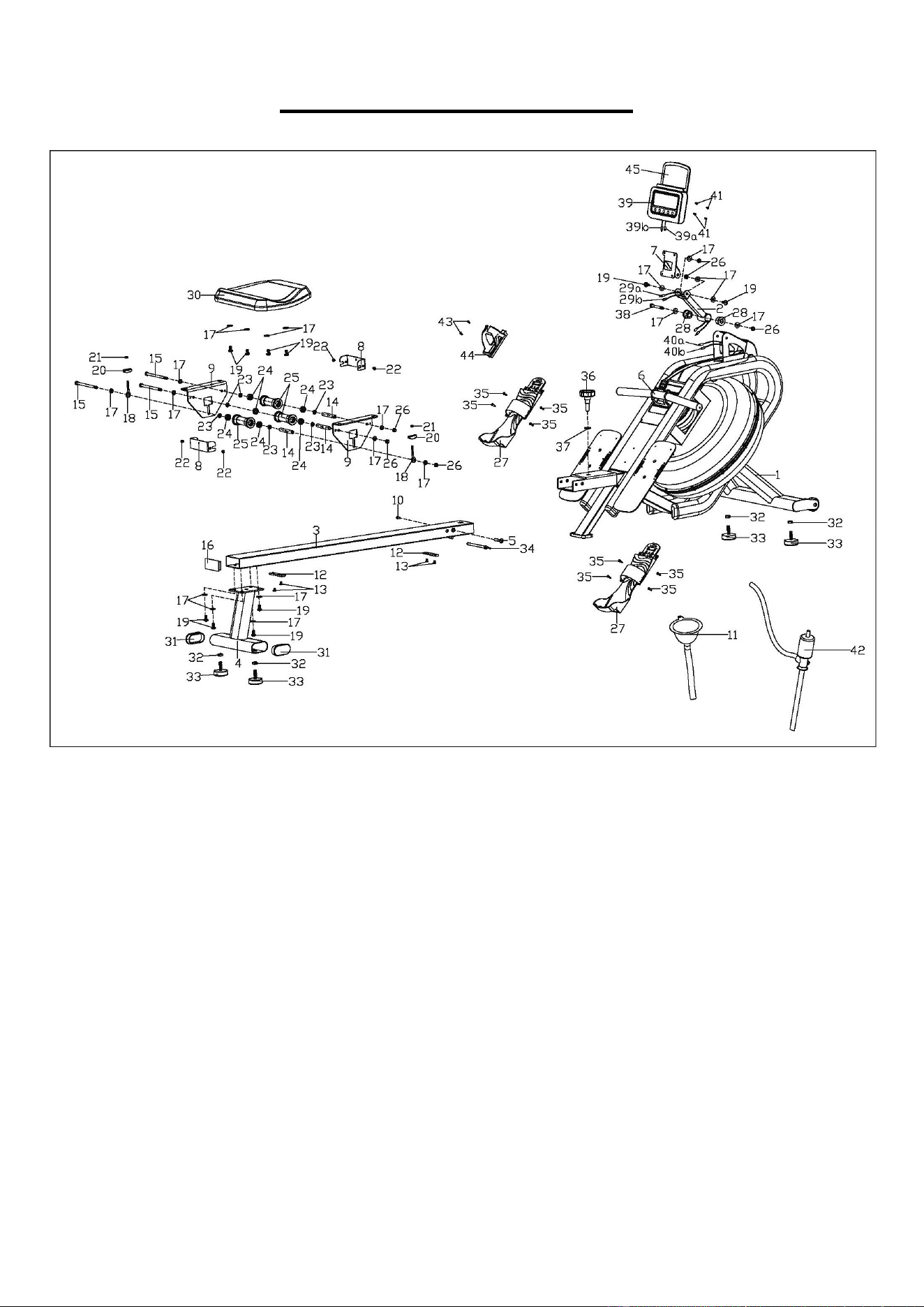
EXPLODED DIAGRAM 1
16
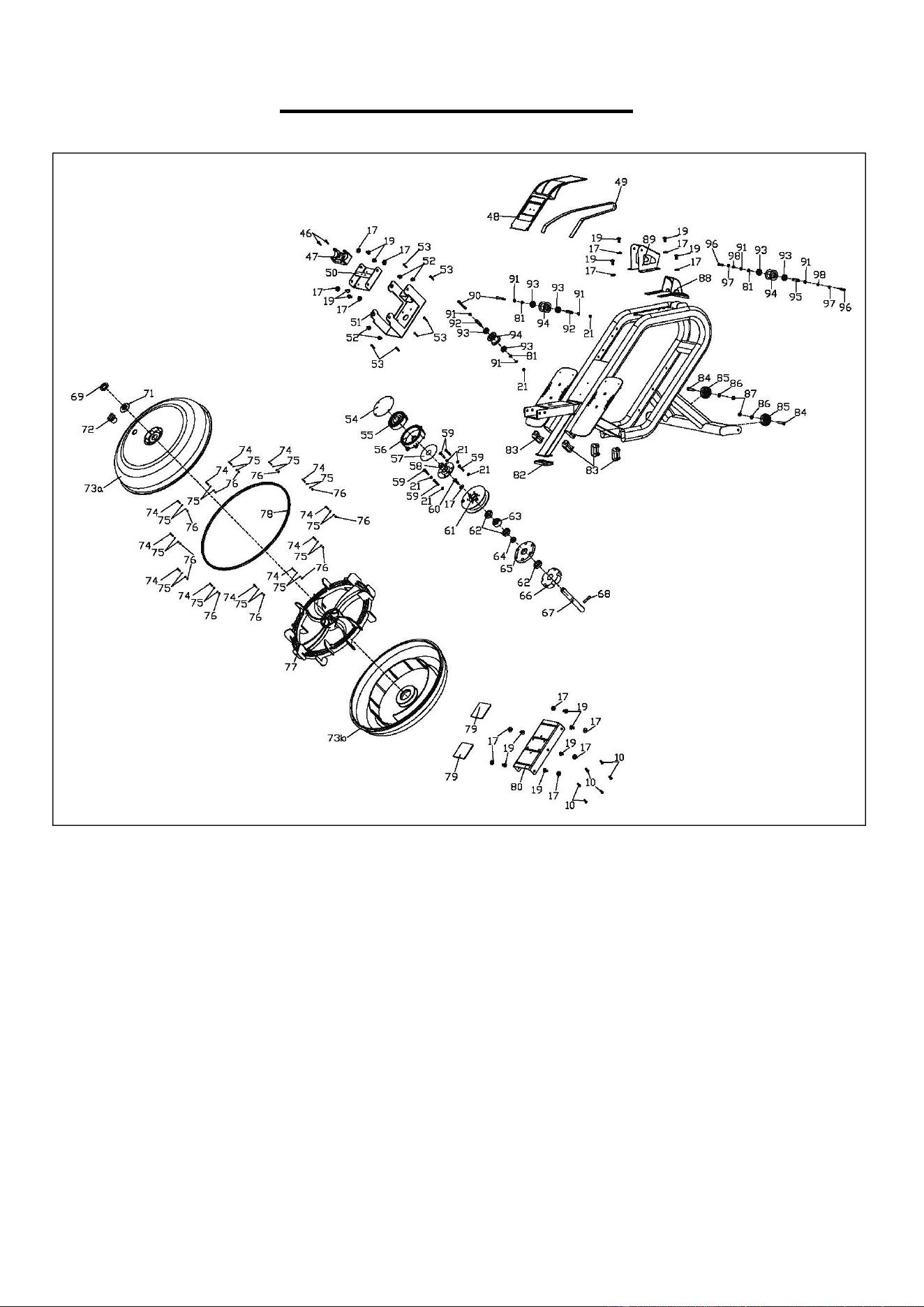
EXPLODED DIAGRAM 2
17
PARTS LIST
No.
Description
Spec.
Qty.
No.
Description
Spec.
Qty.
1
Main Frame
1
43
Screw
M5X10
2
2
Meter Support Tube
1
44
Bottle Holder
1
3
Slide Rail
1
45
Tablet Holder
1
4
Rear Support Tube
1
46
Screw
M5X15
2
5
Bolt
Ф10XL94.5
1
47
Handlebar Holder
1
6
Pull Bar
1
48
Protective Cover
1
7
Meter Plate
1
49
Mesh Belt
t1.5X22X3000
1
8
U Shape Baffle
2
50
Board
1
9
Supporting Board
2
51
Fixed Plate
1
10
Bolt
M6XL15
7
52
Screw
M8X15
4
11
Funnel
1
53
Screw
ST4.2X16
6
12
Limit Cushion
75X18X5
2
54
PC Board 3
Ф112X0.5
1
13
Screw
M6X10
4
55
Volute Spring
t0.5X22X5080
1
14
Spacer
Ф13XФ8X78
3
56
Volute Wheel
Ф115X110X34.
5
1
15
Hex Bolt
M8X125
3
57
PC Board 2
Ф90XФ25.2X0
.5
1
16
Square Cap
80X40X2.0
1
58
Volute Spring Axle
Ф85X42.5
1
17
Flat Washer
D8XD20X1.5
35
59
Screw
M6X35
5
18
Adjustable Chain Bolt
M6X50
2
60
Screw
M8X25
1
19
Screw
M8X16
24
61
Belt Wheel
Ф130X34.8
1
20
Adjustable Chain U
Mat
3X30X20
2
62
Bearing
6904-2Z
3
21
Nylon Nut
M6
9
63
Bearing
Ф37XФ20XT1
8
1
22
Screw
M5X7
4
64
Spacer
Ф25XФ20.1X8
1
23
Roller Spacer
Ф15X3.5X4
6
65
Fixed Plate
Ф110X12
1
24
Bearing
608Z
6
66
Raw Cotton
1
25
Roller
Ф40X92
3
67
Rotating Axle
Ф20X163Xm8
1
26
Nylon Nut
M8
6
68
Stainless Steel Pin
Ф8X40
1
27
Pedal
2
69
Small Seal Ring
Small size
1
28
Plastic Bushing
Ф32X13.3
2
70
N/A
-
29a
Extension Wire A
350mm
1
71
Seal Ring
Medium size
1
29b
Extension Wire B
350mm
1
72
Plug
Ф35XФ15X3
1
30
Seat
1
73a
Upper Tank Cover
1
31
Oval Cap
80X40x2
2
73b
Bottom Tank Cover
1
32
Hex Nut
M10
4
74
Screw
M3X20
12
33
Adjustable Foot Pad
Ф52X19
4
75
Flat Washer
D3.5XФ7X0.5
24
34
Pull Pin
Ф8XL105XA100
1
76
Nylon Nut
M3
12
35
Screw
M4X5
8
77
Impeller
463X124
1
36
Knob
M12X30XФ1
1
78
Seal Ring
Large size
1
37
Flat Washer
D12XФ24X2.0
1
79
Silicone Cushion
80X80X3.0
2
38
Bolt
M8X70
1
80
Supporting Board
1
39
Meter
HT-109
1
81
Wave Washer
D10XФ15X0.3
3
39a
Meter Wire A
100mm
1
82
Rubber Foot Pad
1
39b
Meter Wire B
100mm
1
83
Oblate Plug
4
40a
Sensor Wire A
500mm
1
84
Bolt
M8X38
2
40b
Sensor Wire B
500mm
1
85
Transportation Wheel
Ф50XФ8XL21
2
41
Screw
M5X15
4
86
Flat Washer
D8XФ16X1.5
2
42
Pumping Siphon
1
87
Nylon Nut
M8XH6.5
2

18
No.
Description
Spec.
Qty.
No.
Description
Spec.
Qty.
88
Protective Cover
1
95
Belt Wheel Axle
1
89
Fixed Plate
1
96
Hex Bolt
M6X15
2
90
Hex Bolt
M6X55
2
97
Spring Washer
D6
2
91
Axle Washer
D10
6
98
Flat Washer
D6
2
92
Belt Wheel Axle
Ф10X40XФ6.1
2
99
Spanner
S10,S13,S14,S15,
S17
1
93
Bearing
6000
6
100
Allen Wrench
S5
1
94
Belt Roller
Ф45X35
3
101
Allen Wrench
S6
1
Version 1.0