Loading ...
Loading ...
Loading ...
8
ASSEMBLY
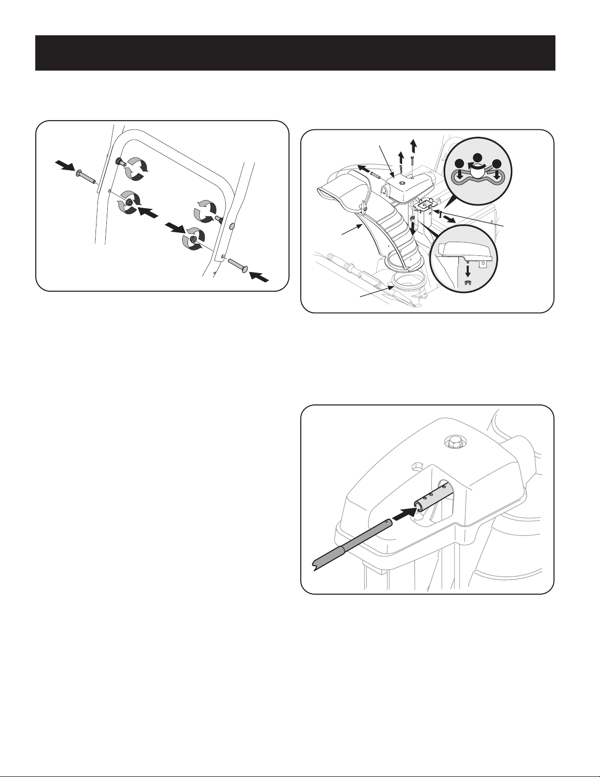
6. Attach the two carriage screws and lock nuts removed in Step 2. Finish
securing the handle by tightening the top two lock nuts loosened in Step 2.
See Figure 4.
Figure 4
7. Remove and discard any rubber bands, if present. They are for packaging
purposes only.
8. On units equipped with cable guides on top of the engine, check that all
cables are properly routed through the cable guide. Then pull the cables
towards the chute and pull the cable tie on the engine snug on the cables to
secure in place.
NOTE: For smoothest operation, cables should all be to the left of the chute
directional control rod.
Chute Assembly
1. Remove cotter pin, wing nut, and hex screw from chute control head and
clevis pin and bow-tie cotter pin from chute support bracket. See Figure 5.
Chute Control Head
Chute
1
1
2
Chute
Support
Bracket
Chute Base
Figure 5
NOTE: For smoothest operation, the cables should all be to the left of the chute
control rod.
2. Insert the round end of the chute control rod into input of chute control
head. Push rod as far into the chute control head as possible, keeping the
holes in the rod pointing upward. See Figure 6.
Figure 6
Loading ...
Loading ...
Loading ...