Loading ...
Loading ...
Loading ...

26
3.8 DIGITAL INPUTS
Stereo digital audio sources can be connected using coaxial or
optical cables. The MDA16 has two digital optical inputs, and
two digital coaxial inputs and The MDA8 has one digital optical
input. All of these inputs support the PCM stereo format (up
to 24-bit / 192kHz). If using sources that have an option for
selecting between PCM and Bitstream (or Dolby Digital) audio
output, select PCM. If the source outputs a non-PCM stream
(such as a Dolby or DTS stream), the audio will mute.
3.9 DIGITAL OUTPUT (MDA16 ONLY)
The digital optical output on the MDA16 provides a repeat
function to feed an additional MDA (or any other component
that accepts digital optical input). This output supports up
to 24-bit/192kHz and can be congured to output any of the
MDA’s digital inputs (including digital coaxial). Select any of the
digital inputs via the web interface by clicking on Digital Out
Source in the General > Preferences screen and selecting the
appropriate digital input.
3.10 ANALOG INPUTS
Connect stereo analog sources using RCA cables. The MDA16
has eight stereo RCA line inputs. The MDA8 has four stereo
RCA line inputs.
3.11 ANALOG OUTPUTS (MDA16 ONLY)
The MDA16 has two stereo analog RCA line outputs. Any audio
source connected to the Analog 6 input passes unaltered to
the Analog 6 Out. Any audio source connected to the Analog
7 input passes unaltered to the Analog 7 Out. These act as
“pass-throughs” and work even when the MDA is in standby
or powered o.
3.12 POWER
Insert a power cord into the MDA’s AC input. Plug the cord into
a wall outlet. Ensure that the AC supply matches the voltage
rating shown on the back of the MDA. The 230V models sup-
port voltages from 220V to 240V.
3.13 TRIGGER CONNECTIONS
The trigger connection allows the MDA to be turned on or o
via the trigger input. When either Trig In 3.5mm (1/8”) mini-
jack receives power (5–24 volts DC or AC) from an upstream
component, the MDA turns on (Auto-On delay applies). When
it stops receiving power, the MDA turns o immediately. The
second Trig In jack allows you to run a cable out to daisy-chain
and trigger additional MDAs. For this function to work the On
Mode switch must be set to Trig. Please note, do not connect
triggers from two upstream components at the same time. Al-
ways use one as an input and one as an output.
The trigger also works with the On Mode switch set to Auto.
See section 3.15 for additional details.
3.14 RS-232 CONNECTION
The RS-232 connection allows connection to a compatible con-
trol system. The control system should be congured to use
115200/8-N-1, no ow control, protocol. The cable connection
should be one to one.
3.15 ON MODE SWITCH
With the three-way switch located on the back panel, you set
the way the MDA turns on and o.
• Trig: This sets the MDA to turn on and o when it receives
a signal on its Trig In connection. See section 3.13 for ad-
ditional details.
• Auto: This sets the MDA to turn on when it detects an in-
coming signal on any of its digital or analog audio inputs.
When the MDA stops detecting all incoming audio signals,
it enters standby mode after approximately 20 minutes
(by default). O and on times can be adjusted via the web
interface. Go to General > Preferences > Auto-O Delay
and Auto-On delay. The trigger input also works in this
mode. The MDA will turn on when a signal is applied to Trig
In, even if no audio signal is detected. The unit will enter
standby mode after the Auto-O delay once the trig signal
is removed and no audio signal is detected.
• Ext Cmd: This sets the MDA to ONLY turn on and o when
it receives commands from an IP or RS-232 control system.
Note that commands can be sent in any mode of operation.
For example, the volume may be changed whether the switch
is set to Auto or Trig. You will not be able to turn on a zone
using a command if in Trig mode and the trigger input is
de-asserted, but a turn on command will work if the On Mode
switch is set in Auto mode.
3.16 MASTER POWER SWITCH
This switch is wired directly to the AC mains and turns on and
o all power going to the MDA.
3.17 DHCP OR FACTORY IMAGE RESET
This reset button allows you to manually reset the MDA’s net-
work connection DHCP settings or restore the MDA to the
original factory image. See section 7 for additional details.
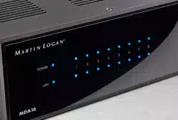
3.18 ID INDICATOR
When multiple MDAs are in a rack, you can quickly identify
each MDA by making use of the ID indicator. Use a web brows-
er to connect to the control interface of the rst MDA and en-
able Unit ID under General > Preferences. The ID light on the
Loading ...
Loading ...
Loading ...