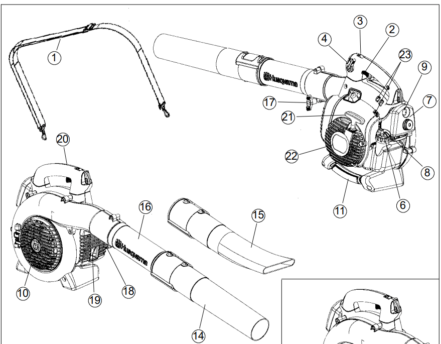
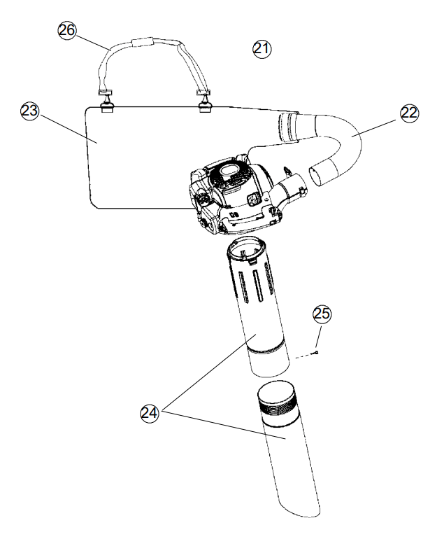
21. Vacuum device with collection components consisting of items 22--26 below
22. Collection bag tube
23. Collection bag
24. Vacuum tube in two sections
25. Screw
26. Shoulder strap
Safety equipment
The following equipment on the blower is designed for protecting personnel and materials. These components should receive special attention whenever you operate, inspect and service the blower.
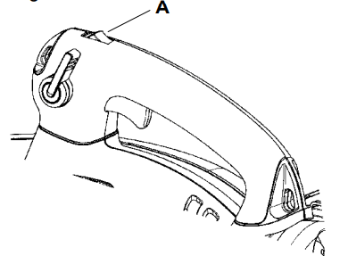
Stop switch
The stop switch (A) is used to stop the engine.
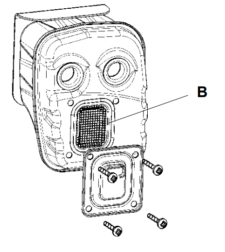
Muffler
The muffler is designed to give the lowest possible noise level and to direct the engine’s exhaust fumes away from the operator. Mufflers fitted with catalytic converters are also designed to reduce harmful exhaust components.
The engine exhaust fumes are hot and can contain sparks, which may cause fire if they come in contact with dry or flammable material.
Some blower models, especially those sold in countries where the climate is dry, are equipped with a spark arresting screen (B). This screen must be cleaned or replaced at specific intervals. See the Maintenance section.
WARNING: The muffler is extremely hot while the engine is running and after it has stopped. DO NOT TOUCH THE MUFFLER IF IT IS HOT! This can cause severe burns.
Other equipment
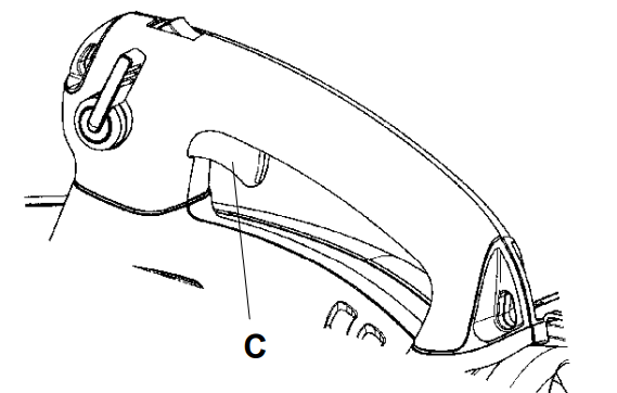
Throttle trigger
The speed and the output of the engine are regulated by the throttle trigger (C).
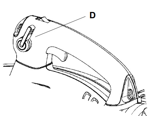
Variable speed control
The variable speed control (D) is designed to allow setting engine speed as necessary during blower use only.
To avoid causing damage to the unit, DO NOT attempt to use the variable speed control during starting or during vacuum use.
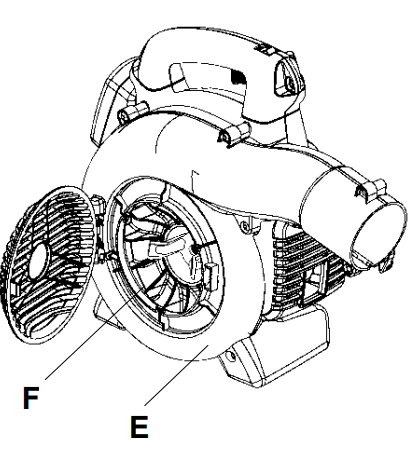
Fan housing
The blower fan housing (E) and the fan impeller (F) provide high performance air discharge.
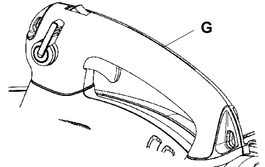
Ground wire
The ground wire (G) reduces static build--up during operation in dry conditions
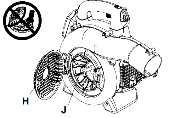
Inlet cover
An inlet cover (H) is located on the side of the fan housing. Opening this cover allows access for cleaning and inspecting the impeller (125BX--SERIES and 125BVX--SERIES only). If the vacuum tube is used, it must be fitted to the opening in the inlet cover. To open the inlet cover, use a tool to lift the edge of the cover opposite the hinge (indicated by arrow on inlet cover).
WARNING: Never start the blower if the inlet cover is not closed, is damaged or cannot be closed (except if the vacuum tube is fitted).
Cutters
(125BX--SERIES and 125BVX--SERIES)
Two cutters (J) are fastened to the impeller. The cutters are there to mulch leaves and other debris that have been vacuumed before they enter the collection bag.
Blower tube and nozzle
NOTE: The tube clamp bolt and nut must be installed prior to initial use (see the general description of the blower on page 6).
The blower tube (K) has a pegged slot mounting system to the unit. To install or remove the blower tube (or collection bag tube for the 125BVX--SERIES), the tube clamp bolt must be removed. Align slot in the blower air outlet with the raised rib on the tube and insert tube until the holes in the tube and housing align. Re--insert the tube clamp bolt and tighten.
The nozzles (L) have a bayonet mount for connection to the blower tube. Air is channeled through the blower tube to the nozzles, where the air discharge velocity increases and the air stream discharge pattern is formed to provide best performance. The length of the blower tube can be adjusted by twisting the nozzle to the left to disengage the bayonet mount and sliding the nozzle to the appropriate position. Twist the nozzle to the right until a click is felt to resecure the nozzle.
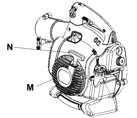
Starter device and starter handle
The starter device (M) is located on the side of the engine shrouding and engages the crankshaft only when the starter handle (N) is pulled.
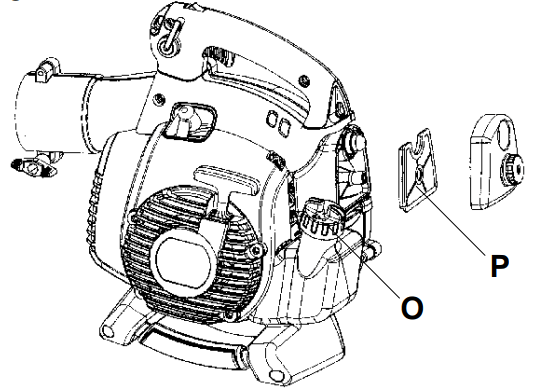
Fuel cap
The fuel cap (O) is located at the rear of the engine shrouding on the fuel tank and has a seal to prevent fuel from leaking out.
Air filter
The air filter (P) consists of a fiber filter medium in a resilient frame. The air filter should be cleaned at specific intervals (see Maintenance section). Otherwise, the blower will consume too much fuel, the performance will be reduced and an oily deposit may form on the spark plug electrodes.
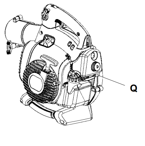
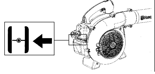
Choke
The choke (Q) is located below the air filter cover and should be used every time the engine is cold--started.
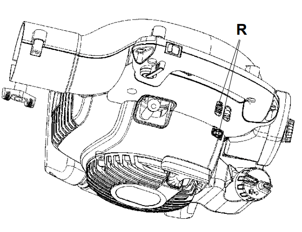
Adjusting the carburetor
NOT FOR ALL MODELS
There are three adjusting screws (R) for adjusting the carburetor:
Low speed jet
High speed jet
Adjustment screw for idling
Adjusting the carburetor involves adapting the engine to local operating conditions, e.g. climate, altitude, gasoline and type of two--stroke engine oil used. For details about carburetor adjustment, see the Maintenance section.
Fuel handling
Fuel mixture
CAUTION!
The machine is equipped with a two--stroke engine and must always be run using a mixture of gasoline and two-- stroke engine oil. It is important to accurately measure the amount of oil to be mixed to ensure that the correct mixture is obtained. When mixing small amounts of fuel, even small inaccuracies can drastically affect the ratio of the mixture.
WARNING:
Always ensure there is adequate ventilation when handling fuel.
Gasoline
CAUTION!
Always use high quality unleaded gasoline
This engine is certified to operate on unleaded gasoline.
The lowest recommended octane rating is 87. If you run the engine on lower octane rating than 87, “knocking” can occur. This leads to an increased engine temperature, which can result in a serious engine breakdown.
When working at continuous high revs a higher octane rating is recommended.
Two-stroke oil
For great results and performance use HUSQVARNA two-stroke oil, which is specially formulated for our two-stroke engines. Mixture 1:50 (2%).
To maximize the life of your blower, you may choose to use a high quality synthetic oil formulated for two-stroke engines. Mixture 1:50 (2%).
Never use two-stroke oil intended for water--cooled outboard engines, sometimes referred to as outboard oil.
Never use oil intended for four-stroke engines.
Gasoline
Two-stroke oil
2% (1:50)
U.S. gallon
U.S. fl. oz.
1
2 1/2
2 1/2
6 1/2
5
12 7/8
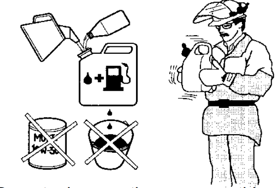
Mixing
Always mix the gasoline and oil in a clean container intended for fuel.
Always start by filling half the amount of the gasoline to be used. Then add the entire amount of oil. Mix (shake) the fuel mixture. Add the remaining amount of gasoline
Mix (shake) the fuel mixture thoroughly before filling the machine’s fuel tank.
Do not mix more than one month’s supply of fuel at a time.
If the machine is not used for some time, the fuel tank should be emptied and cleaned.
WARNING:
The catalytic converter muffler gets very hot during and after use. This also applies during idling. Be aware of the fire hazard, especially when working near flammable substances and/or vapors.
Fueling
WARNING:
Taking the following precautions, will lessen the risk of fire: Do not smoke or place hot objects near fuel. Always shut off the engine before refueling. Always stop the engine and let it cool for a few minutes before refueling. When refueling, open the fuel cap slowly so that any excess pressure is released gently. Tighten the fuel cap carefully after refueling. Always move the machine away from the refueling area before starting.
STARTING AND STOPPING
Clean the area around the fuel cap. Contamination in the tank can cause operating problems
Ensure that the fuel is well mixed by shaking the container before filling the tank.
Starting and stopping
WARNING: Never start the blower if the inlet cover is not closed, is damaged or cannot be closed (except if the vacuum tube is fitted).
Cold engine
Primer bulb: Press the primer bulb 10 times until fuel begins to fill the bulb. The primer bulb need not be completely filled
Choke: Move the blue engine choke lever over to the FULL CHOKE (closed) position.
Starting: Hold the body of the machine on the ground using your left hand
(CAUTION! Not with your foot!). Firmly grip the starter rope handle with your right hand. DO NOT squeeze throttle trigger. Slowly pull out the cord until you feel some resistance (the starter pawls grip); then quickly and powerfully pull the cord.
WARNING: Never wrap the starter cord around your hand.
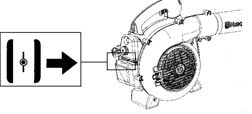
Pull starter handle until engine attempts to run, but no more than 3 pulls. Move choke to ½ position and pull the cord until the engine starts and runs. Allow the engine to warm up for approximately 10 seconds; then, move the choke to the OFF CHOKE (opened) position.
NOTE:
If engine dies, return blue engine choke lever to the closed position and repeat starting steps.
CAUTION!
Do not pull the starter cord all the way out and do not let go of the starter handle when the cord is fully extended. This can damage the machine.
Warm engine
With a warm engine, squeeze and hold the throttle trigger. Move choke to ½ position. Pull starter rope sharply while squeezing throttle trigger until engine runs. Move the choke to the OFF CHOKE (opened) position.
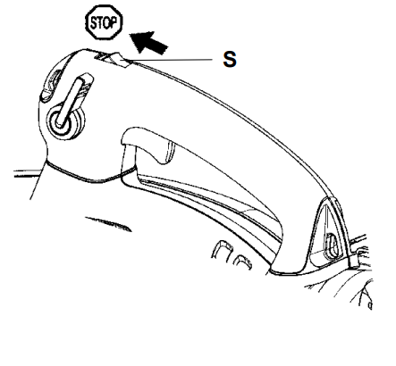
Stopping
To stop the engine, push and release the engine STOP switch (S).
USING THE BLOWER
To blow away debris on the ground
Fitting the blower tube and nozzle on the blower
WARNING: When fitting the blower tube and nozzle, the engine must be switched off.
The blower tube (T) has a pegged slot mounting system to the unit. To install or remove the blower tube (or collection bag tube for 125BVX--SERIES), the tube clamp bolt must be removed. Align slot in the blower air outlet with the raised rib on the tube and insert tube until the holes in the tube and housing align. Re--insert the tube clamp bolt and tighten.
The nozzles (U) have a bayonet mount for connection to the blower tube. Air is channeled through the blower tube to the nozzles, where the air discharge velocity increases and the air stream discharge pattern is formed to provide best performance. The length of the blower tube can be adjusted by twisting the nozzle to the left to disengage the bayonet mount and sliding the nozzle to the appropriate position. Twist the nozzle to the right until a click is felt to re--secure the nozzle.
Blowing
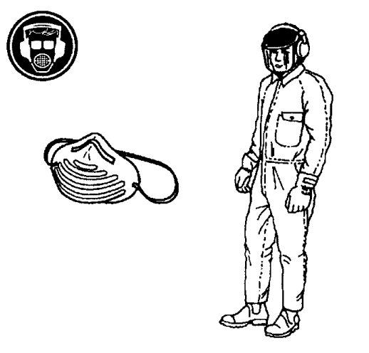
Before you begin blowing, put on the required safety equipment.
WARNING:
When working with the blower, wear the required personal safety equipment:
1. Hearing protection.
2. Eye protection.
3. Protective gloves.
4. Face mask in dusty environments.
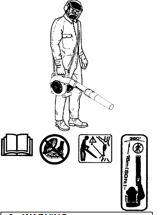
125BVX--SERIES can be used with a shoulder strap for extra comfort. The strap should be worn over the shoulder as shown.
WARNING:
Never point the blower nozzle at people or animals. The high--velocity air stream can contain particles that may cause serious injury, especially if the blower has previously been used for vacuuming. Be careful, particularly if left hand operation is applied. Avoid any direct body contact with inlet cover area. Keep jewelry, loose clothing, or clothing with loosely hanging straps, ties, tassels, etc., away from inlet cover area.
MAINTENANCE
Maintenance Safety
The owner is responsible for the performance of all required maintenance as defined in the operator’s manual.
Disconnect the spark plug before performing maintenance, except carburetor adjustments
WARNING: Improper maintenance could result in serious engine damage or in serious injury.
Carburetor
Your Husqvarna product has been designed and manufactured to specifications that reduce harmful emissions. After the engine has used 8--10 tanks of fuel, the engine will be run--in. To ensure that it continues to run at peak performance and to minimize harmful exhaust emissions after the run--in period, ask your servicing dealer to adjust your carburetor.
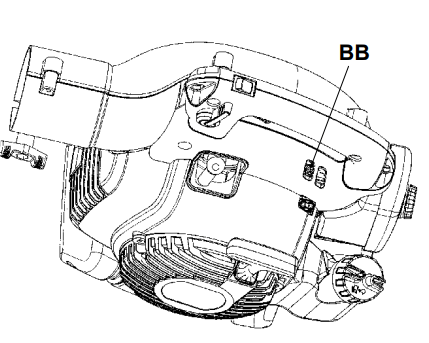
Function
The carburetor governs the engine’s speed via the throttle control. Air and fuel are mixed in the carburetor.
The T--screw (BB) regulates the throttle setting at idle speed. If the T--screw is turned clockwise this gives a higher idle speed; turning it counterclockwise gives a lower idle speed.
Basic setting
The basic carburetor settings are adjusted during testing at the factory. Fine adjustment should be carried out by a skilled technician.
Muffler
Some mufflers are fitted with catalytic converters. See the Technical data section to find out if your machine is equipped with a catalytic converter.
The muffler is designed to dampen the noise level and to direct the exhaust fumes away from the user. The exhaust fumes are hot and can contain sparks, which can result in fire if the exhaust fumes are directed towards a dry and flammable material.
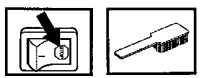
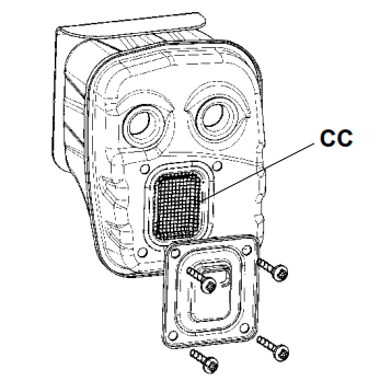
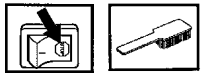
Some mufflers are equipped with a special spark arresting screen (CC). If your machine is fitted with this type of screen, it should be cleaned regularly. To access the screen, remove the outlet cover on the front of the muffler. Use a wire brush to clean the screen. On mufflers without a catalytic converter the screen should be cleaned weekly, or replaced if necessary.
On mufflers fitted with a catalytic converter the screen should be checked and cleaned monthly. If the screen is damaged it should be replaced. If the screen is frequently blocked, this can be a sign that the function of the catalytic converter is impaired. Contact your dealer to inspect the muffler. A blocked screen will cause the engine to overheat resulting in damage to the cylinder and piston.
CAUTION! Never use a machine that has a faulty or loose muffler. Ensure the muffler bolts are tight.
WARNING:
Mufflers fitted with catalytic converters get very hot during use and remain so for some time after stopping. This also applies at idle speed. Contact can result in burns to the skin. Remember the risk of fire!
Bear in mind that: Engine exhaust fumes contain carbon monoxide, which can cause carbon monoxide poisoning. For this reason you should not start or run the machine indoors, or anywhere that is poorly ventilated. The exhaust fumes from the engine are hot and may contain sparks which can start a fire. Never start the machine indoors or near flammable material!
The inside of the muffler contain chemicals that may be carcinogenic. Avoid contact with these elements in the event of a damaged muffler.
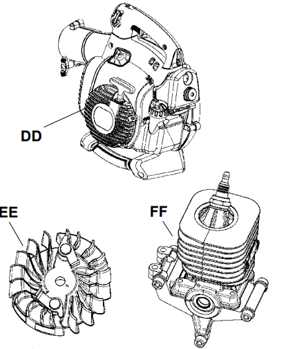
Cooling system
The engine is equipped with a cooling system for maintaining the right operating temperature
The cooling system consists of the following components:
1. Air intake on the starter device (DD).
2. Fan blades on the flywheel (EE).
3. Cooling fins on the cylinder (FF).
4. Cylinder cowling (guides cooling air flow against cylinder surfaces).
Clean the cooling system by brushing once a week, or more often, if necessary.
A dirty or blocked cooling system will cause the blower to overheat and this will damage the cylinder and piston.
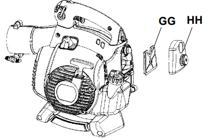
Air filter
The air filter (GG) must be regularly cleaned to remove dust and dirt in order to avoid:
Carburetor malfunctions S Starting problems
Loss of engine power
Unnecessary wear to engine parts
Excessive fuel consumption
Elevated content of harmful exhaust fumes.
Clean the filter every 25 hours, or more regularly if conditions are exceptionally dusty
Cleaning the air filter
Remove the air filter cover (HH) and take out the filter. Wash it clean in warm, soapy water. Rinse thoroughly. Ensure that the filter is dry before reinstalling it.
An air filter that has been in use for a long time cannot be cleaned completely. The filter must therefore be replaced with a new one at regular intervals
CAUTION! A damaged air filter must always be replaced.
Spark plug
The spark plug condition is influenced by:
Incorrect carburetor adjustment.
An incorrect fuel mixture (too much or incorrect type of oil).
Poor quality gasoline and/or oil
A dirty air filter.
These factors cause deposits on the spark plug electrodes, which may result in operating problems and starting difficulties. If the machine is low on power, difficult to start or runs poorly at idle speed: always check the spark plug first before taking any further action. If the spark plug is dirty, clean it and check that the electrode gap is 0.024″ (0.6 mm). The spark plug should be replaced after about a month in operation or earlier if necessary.
CAUTION! Always use the recommended spark plug type! Use of the wrong spark plug can damage the piston/cylinder.
Maintenance schedule
Below you will find some general maintenance instructions.
Daily maintenance
Clean the exterior surfaces of the blower.
Check that the variable speed control and the throttle trigger function in a safe manner. Replace damaged parts.
Check that the stop switch works properly. Replace if necessary.
Clean the air filter. Replace if necessary.
125BX--SERIES and 125BVX--SERIES: Check that the inlet cover can be locked in the closed position. Carefully check that the fan impeller is clean, especially if the blower has been used for collecting debris (vacuuming).
Check that all nuts and screws are properly tightened.
Check that all the housings are free of cracks. Replace damaged parts.
125BX--SERIES and 125BVX--SERIES: Check that the collection bag is intact and that the zipper works. Replace it if necessary.
Weekly maintenance
Check the condition of the starter device, the starter cord and the tensioning spring. Replace damaged parts.
Check the condition of the air intake at the starter device. Remove debris if it is clogged.
Clean the outside of the spark plug. Remove it and check the electrode gap. Adjust the gap to 0.024″ (0.6 mm), or replace the spark plug. Use resistor spark plug Champion RCJ--8Y or equivalent.
Clean the fan blades on the flywheel.
Clean or replace the spark arresting screen (not on mufflers with a catalytic converter).
Clean the carburetor area.
Clean the air filter
Monthly maintenance
Clean the fuel tank.
Clean the outside of the carburetor and the area around it.
Clean the fan blades on the flywheel and the area around it.
Check fuel lines for cracks or other damage. Change if necessary.
Change the fuel filter in fuel tank.
Check all cables and connections. Replace damaged parts.
Replace the spark plug. Use spark plug Champion RCJ--8Y or equivalent.
The 125B is just a blower. The 125BVx is both a blower and a mulcher/vaccuum, costing $30 to $40 more but still using the same motor and basic housing of the 125B.
#2 Will running standard ethanol fuel void the warranty?
It will not void the warranty because it takes longer for the ethanol to dissolve the gas lines. Ethanol containing fuels will not ruin the complete blower,only the fuel lines and thus also clog the carb with the debris,requiring replacement. Some farm stores and gas stations sell pure unadulterated gasoline and all the big box home improvement stores stock alcohol-free premixed fuel by the quart and by the gallon. Use it and save yourself a bunch of headaches. I've been there and had to do that. Ebay is full of listings for replacement carbs (and fuel lines)for damaged ones,due to this issue.
#3 What type of gas does this one use? Is it non-ethanol as well?
There is no mention of ethanol in the manual. It uses regular gas, 87 octane minimum although higher is recommended. It is 2-cycle (2-stroke) with a common 50:1 mixture.

 WARNING: Never start the blower if the inlet cover is not closed, is damaged or cannot be closed (except if the vacuum tube is fitted).
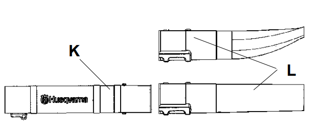
 WARNING:
  Gasoline
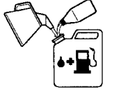
 WARNING:
 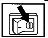 Fueling
 WARNING:
 Starting and stopping
 WARNING: Never start the blower if the inlet cover is not closed, is damaged or cannot be closed (except if the vacuum tube is fitted).
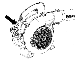
 WARNING: When fitting the blower tube and nozzle, the engine must be switched off.
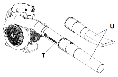
 WARNING: Improper maintenance could result in serious engine damage or in serious injury.
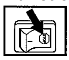 Function