
EN, English
Operator's manual
115H
Read the operator's manual carefully and make sure that you
understand the instructions before you use the product.

Contents
1 Introduction
1.1 Introduction.................................................3
1.2 Product overview........................................4
1.3 Symbols on the product..............................5
1.4 Symbols on the display.............................. 5
1.5 Symbols on the battery...............................5
1.6 Menu structure overview............................ 7
1.7 Display........................................................8
1.8 Keypad ...................................................... 8
2 Safety
2.1 Safety definitions........................................ 9
2.2 General safety instructions.........................9
2.3 Safety instructions for operation...............11
3 Installation
3.1 Introduction - Installation.......................... 14
3.2 Before the installation of the wires........... 14
3.3 Before the installation of the product........14
3.4 Installation of the product......................... 19
3.5 To put the wire into position with stakes...20
3.6 To bury the boundary wire or the
guide wire....................................................... 20
3.7 To extend the boundary wire or the
guide wire....................................................... 20
3.8 After the installation of the product...........21
3.9 To do the product settings........................21
4 Operation
4.1 The ON/OFF button..................................27
4.2 To start the product.................................. 27
4.3 Operating modes......................................27
4.4 To stop the product.................................. 28
4.5 Switch off..................................................28
4.6 To charge the battery............................... 29
4.7 Adjust the cutting height........................... 29
5 Maintenance
5.1 Introduction - maintenance.......................30
5.2 Clean the product..................................... 30
5.3 Replace the blades...................................31
5.4 Firmware update...................................... 31
5.5 Battery...................................................... 32
5.6 Winter service...........................................33
6 Troubleshooting
6.1 Introduction - troubleshooting...................34
6.2 Fault messages........................................ 34
6.3 Information messages.............................. 38
6.4 Indicator lamp in the charging station.......39
6.5 Symptoms................................................ 40
6.6 Find breaks in the loop wire..................... 41
7 Transportation, storage and disposal
7.1 Transportation.......................................... 44
7.2 Storage.....................................................44
7.3 Disposal....................................................44
8 Technical data
8.1 Technical data.......................................... 45
8.2 Registered trademarks............................. 47
9 Warranty
9.1 Warranty terms.........................................48
10 Applicable to US/CA market
10.1 Supplier's Declaration of Conformity...... 49
10.2 Compliance requirements...................... 49
2 982 - 003 -

1 Introduction
1.1 Introduction
Serial number:
PIN code:
Product registration key:
The serial number is on the product rating plate and on the product carton.
• Use the serial number to register your product on www.husqvarna.com.
1.1.1 Support
For support about the Husqvarna product, speak
to your servicing dealer.
1.1.2 Product description
Note: Husqvarna regularly updates the
appearance and function of the products. Refer
to
Support on page 3
.
The product is a robotic lawn mower. The product
has a battery power source and cuts the grass
automatically. Collection of grass is not
necessary.
The operator selects the operation settings with
the keys on the keypad. The display shows the
selected and possible operation settings, and the
operating mode of the product.
The boundary wire and the guide wire controls
the movement of the product within the work
area.
982 - 003 - Introduction -
3
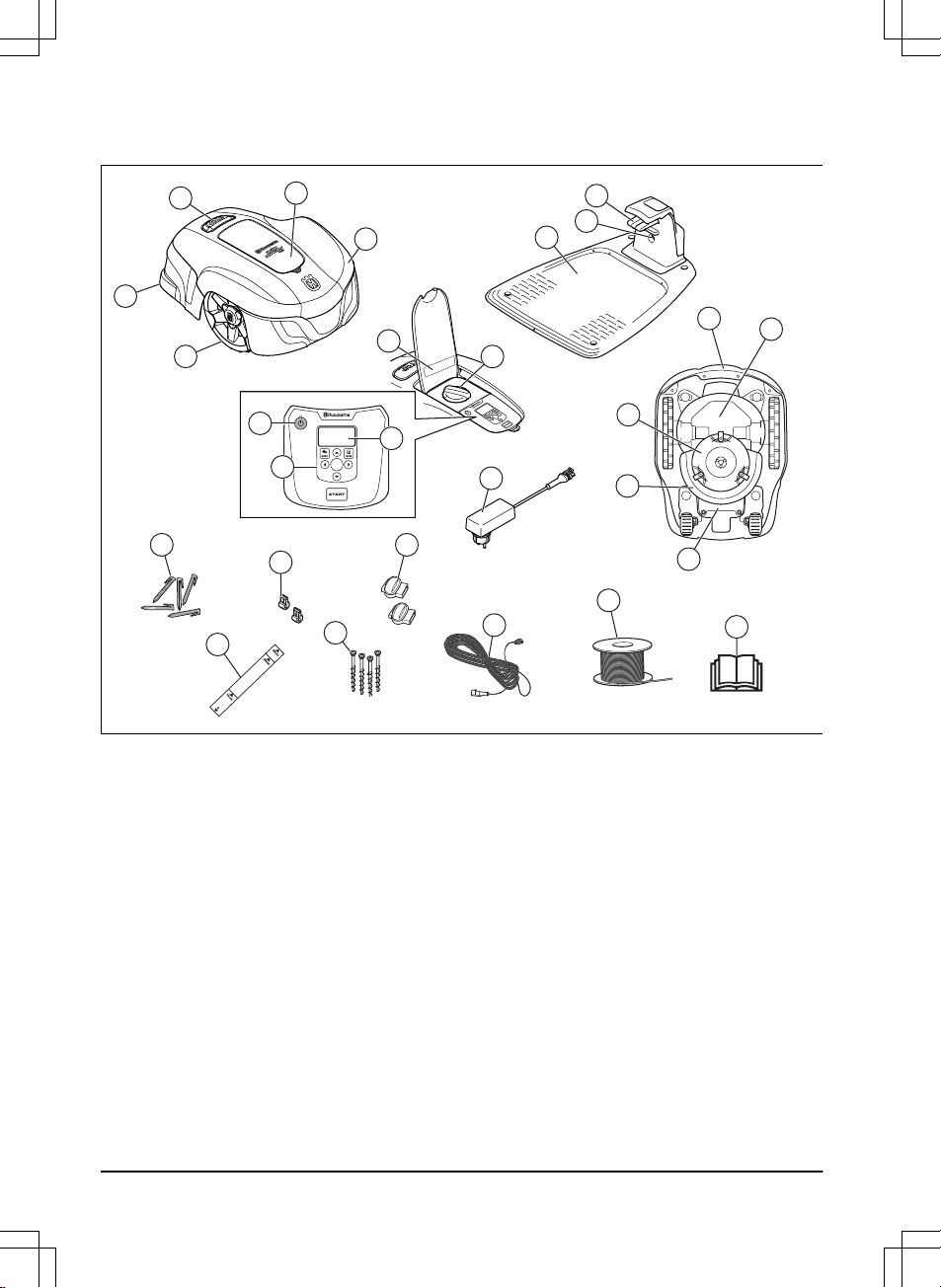
1.2 Product overview
OK
OK
11
13
12
6
16
17
15
14
18
10
9
24
19
26
20
22
23
21
25
27
7
8
1
2
3
5
4
The numbers in the figure represent:
1. Body
2. Hatch to display and keypad
3. Stop button
4. Rear wheels
5. Front wheels
6. Charging station
7. Contact strips
8. LED for operation check of the charging
station, boundary wire and guide wire
9. Cutting height adjustment
10. Rating plate
11. Display
12. Keypad
13. ON/OFF button
14. Cutting system
15. Blade disc
16. Handle
17. Chassis box with electronics, battery and
motors
18. Battery cover
19. Power supply (the appearance of the power
supply may differ depending on market)
20. Stakes
21. Measurement gauge for help when installing
the boundary wire (the measurement gauge
is broken loose from the box)
22. Connector for the loop wire
23. Screws for securing the charging station
24. Couplers for loop wire
25. Low voltage cable
26. Loop wire for boundary loop and guide wire
27. Operator’s Manual and Quick Guide
4 - Introduction 982 - 003 -
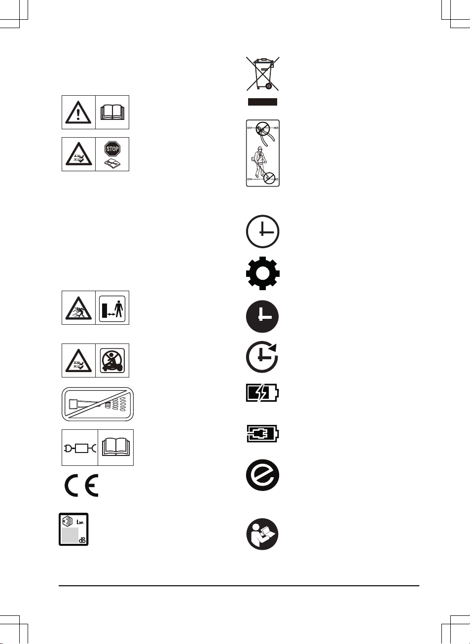
1.3 Symbols on the product
These symbols can be found on the product.
Study them carefully.
WARNING: Read the
user instructions before
operating the product.
WARNING: Operate the
disabling device before
working on or lifting the
product.
The product can only start
if the
ON/OFF button is
pressed and the indicator
lamp is lit. Also, the cor-
rect PIN code must be
entered. Before any in-
spections or maintenance
is done, turn off the prod-
uct and check that the in-
dicator lamp on the
ON/OFF button is not lit.
WARNING: Keep a safe
distance from the product
when operating. Keep
your hands and feet away
from the rotating blades.
WARNING: Do not ride
on the product. Never put
your hands or feet close
to or under the product.
Do not use a high-pres-
sure washer.
Use a detachable power
supply as defined on the
rating label next to the
symbol.
This product conforms to
the applicable EC Direc-
tives.
Noise emission to surroundings. The
product’s emissions are set out in
Technical data on page 45
and on the
rating plate.
It is not permitted to dispose this
product as normal household waste.
Ensure that the product is recycled in
accordance with local legal
requirements.
The low voltage cable must not be
shortened, extended or spliced.
Do not use a trimmer nearby the low
voltage cable. Be careful when
trimming edges where the cables are
placed.
1.4 Symbols on the display
The schedule function controls when
the product cuts the lawn.
The settings function is where the
general settings for the products are
set.
The product will not cut the grass due
to the schedule function.
The product overrides the schedule
function.
The battery indicator shows the charge
level of the battery. When the product
charges the symbol flashes.
The product is put in the charging
station but do not charge the battery.
The product is set in ECO-mode.
1.5 Symbols on the battery
Read the user instructions.
982 - 003 - Introduction -
5

Do not discard the battery into fire and
do not expose the battery to a heat
source.
Do not immerse the battery into water.
6 - Introduction 982 - 003 -
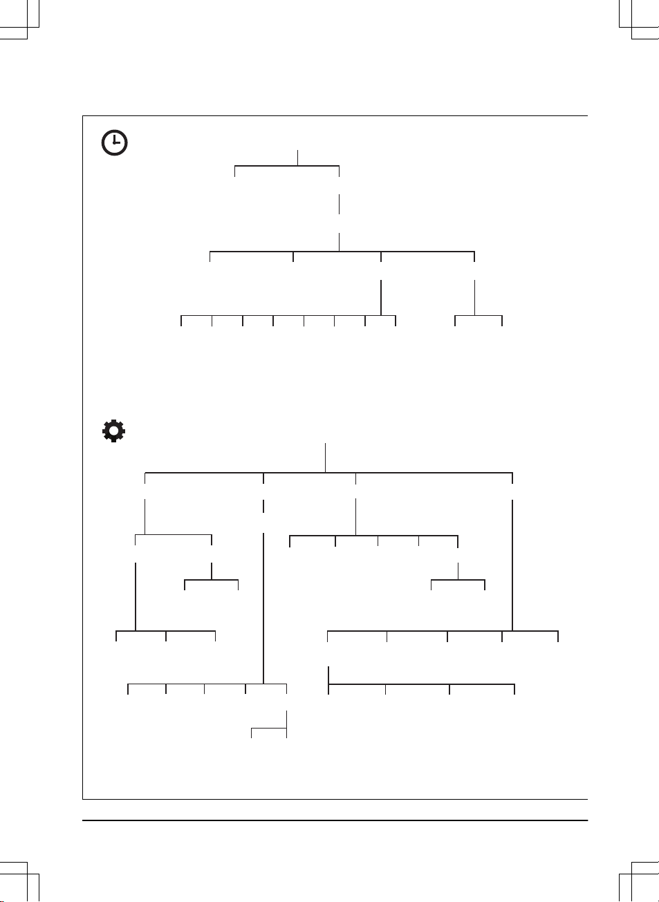
1.6 Menu structure overview
Schedule
Overview week
Period 1
Period 2 Copy
Su
Current
day
All week
SaFrThWeTuMoAll
days
Reset
Wizard Advanced
Settings
Time &
date
Set time Set date Time format Date format
Language Country
Reset all
user setting
About
Security Lawn Coverage
Installation
General
Low Medium
Change
PIN code
New loop
signal
Security level Advanced
Area 1-3
How?
How
often?
How
far?
Disable
ResetTest
More
Starting
point
Drive Past
Wire
ECO
mode
Mower
house
High
Connect@Home
New
pairing
Remove
paired
devices
982 - 003 - Introduction - 7
1.7 Display
The display on the product shows information
and settings of the product.
To access the display, push the
STOP button.
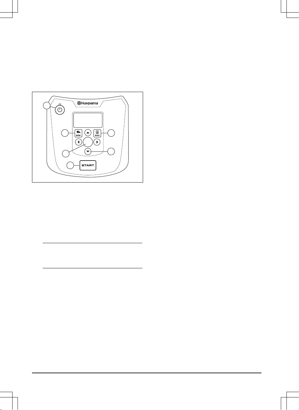
1.8 Keypad
The keypad consists of these buttons:
OK
1
2
3
5
4
6
1. The ON/OFF button is used to turn the
product ON/OFF. The indicator lamp on the
ON/OFF button is an important status
indicator. Refer to
The indicator lamp on
page 27
.
2. The Start button is used to start the
operation of the product.
3. The Menu button is used to go to the main
menu.
Note: The Menu button is also used as a
Back button, that is, when moving back up in
the menu lists.
4. The Mode button is used to choose
operating mode, for example,
Main area
or
Park
.
5. The OK button is used to confirm the chosen
settings in the menus.
6. The
arrow keys are used to navigate in the
menu. The up/down arrow keys are also
used to enter digits, for example, PIN code,
time and date
8 - Introduction 982 - 003 -
2 Safety
2.1 Safety definitions
Warnings, cautions and notes are used to point
out specially important parts of the manual.
WARNING: Used if there is a risk of
injury or death for the operator or
bystanders if the instructions in the
manual are not obeyed.
CAUTION: Used if there is a risk of
damage to the product, other materials
or the adjacent area if the instructions
in the manual are not obeyed.
Note: Used to give more information that is
necessary in a given situation.
2.2 General safety instructions
The following system is used in the Operator’s
Manual to make it easier to use:
• Text written in
italics
is a text that is shown
on the display of the product or is a
reference to another section in the
Operator’s Manual.
• Text written in bold is one of the buttons on
the keypad of the product.
• Text written in
UPPERCASE
and
italics
refer
to the different operating modes available in
the product.
982 - 003 - Safety -
9

2.2.1 IMPORTANT. READ CAREFULLY
BEFORE USE. KEEP FOR FUTURE
REFERENCE
The operator is responsible for accidents or hazards occurring to
other people or property.
This appliance is not intended for use by persons (including chil-
dren) with reduced physical, sensory or mental capabilities (that
could affect a safe handling of the product), or lack of experience
and knowledge, unless they have been given supervision or in-
struction concerning use of the appliance by a person responsible
for their safety.
This appliance can be used by children aged from 8 years and
above and persons with reduced physical, sensory or mental ca-
pabilities or lack of experience and knowledge if they have been
given supervision or instruction concerning use of the appliance in
a safe way and understand the hazards involved. Local regula-
tions may restrict the age of the operator. Cleaning and mainte-
nance shall not be made by children without supervision.
Never connect the power supply to an outlet if the plug or cord is
damaged. Worn or damaged cord increase the risk of electric
shock.
Only charge the battery in the included charging station. Incorrect
use may result in electric shock, overheating or leaking of corro-
sive liquid from the battery. In the event of leakage of electrolyte,
flush with water/neutralizing agent. Seek medical help if it comes
in contact with the eyes.
Use only original batteries recommended by the manufacturer.
Product safety cannot be guaranteed with other than original bat-
teries. Do not use non-rechargeable batteries.
The appliance must be disconnected from the supply mains when
removing the battery.
10 - Safety 982 - 003 -
WARNING: The product
can be dangerous if used
incorrectly.
WARNING: Do not use
the product when
persons, especially
children, or animals, are
in the work area.
WARNING: Keep your
hands and feet away
from the rotating blades.
Never put your hands or
feet close to or under the
product when the motor
is running.
2.3 Safety instructions for operation
2.3.1 Use
• The product is designed to mow grass in
open and level ground areas. It may only be
used with the equipment recommended by
the manufacturer. All other types of use are
incorrect. The manufacturer’s instructions
with regard to operation/maintenance must
be followed precisely.
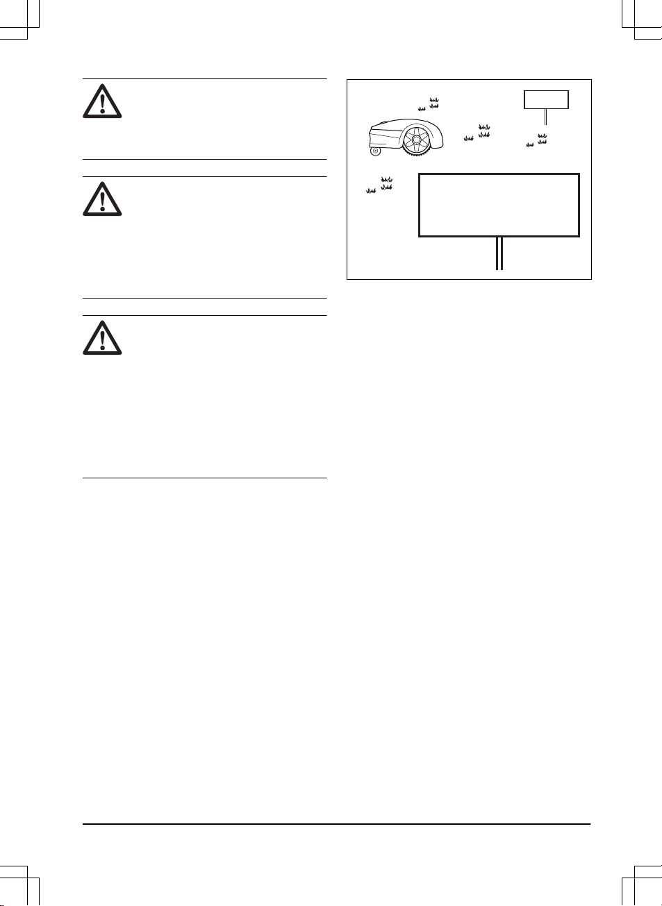
• Warning signs shall be placed around the
work area of the product if it is used in public
areas. The signs shall have the following
text:
Warning! Automatic lawnmower! Keep
away from the machine! Supervise children!
Warning!
Automatic lawnmower!
Keep away from the machine!
Supervise children!
Warning!
Automatic lawnmower!
Keep away from the machine!
Supervise children!
• Use the operating mode
Park
or turn off the
product when persons, especially children,
or animals, are in the work area. It is
recommended to program the product for
use during hours when the area is free from
activity, e.g. at night. Refer to
To set the
schedule on page 22
. Consider that certain
species, e.g. hedgehogs, are active at night.
They can potentially be harmed by the
product.
• The product may only be operated,
maintained and repaired by persons that are
fully conversant with its special
characteristics and safety regulations.
Please read the Operator’s Manual carefully
and make sure you understand the
instructions before using the product.
• It is not permitted to modify the original
design of the product. All modifications are
made at your own risk.
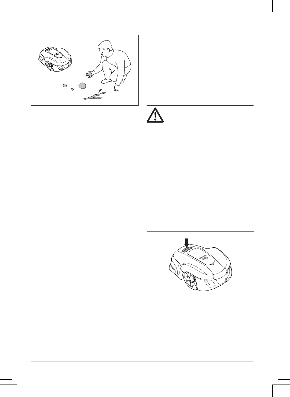
• Check that there are no stones, branches,
tools, toys or other objects on the lawn that
can damage the blades. Objects on the lawn
can also lead to the product getting stuck.
Help may be required to remove the object
before the product can continue mowing.
Always turn off the product using the
ON/OFF button before clearing a blockage.
982 - 003 - Safety -
11
• Start the product according to the
instructions. When the product is turned on,
make sure to keep your hands and feet
away from the rotating blades. Never put
your hands and feet under the product.
• Never touch moving hazardous parts, such
as the blade disc, before it has come to a
complete stop.
• Never lift up the product or carry it around
when it is turned on.
• Do not let persons who do not know how the
product works and behaves use it.
• The product must never be allowed to
collide with persons or other living creatures.
If a person or other living creature comes in
the product’s way it shall be stopped
immediately. Refer to
To stop the product on
page 28
.
• Do not put anything on top of the product or
its charging station.
• Do not allow the product to be used with a
defective guard, blade disc or body. Neither
should it be used with defective blades,
screws, nuts or cables. Never connect a
damaged cable, or touch a damaged cable
before it is disconnected from the supply.
• Do not use the product if the
ON/OFF button
does not work.
• Always switch off the product using the
ON/OFF button when the product is not in
use. The product can only start when the
ON/OFF button has been turned on and the
correct PIN code has been entered.
• HUSQVARNA does not guarantee full
compatibility between the product and other
types of wireless systems such as remote
controls, radio transmitters, hearing loops,
underground electric animal fencing or
similar.
• Metal objects in the ground (for example
reinforced concrete or anti-mole nets) can
result in a stoppage. The metal objects can
cause interference with the loop signal
which then can lead to a stoppage.
• Operation and storage temperature is 0-50
°C / 32-122 °F. Temperature range for
charging is 0-45 °C / 32-113 °F. Too high
temperatures might cause damage to the
product.
2.3.2 Battery safety
WARNING: Lithium-ion batteries can
explode or cause fire if disassembled,
short-circuited, exposed to water, fire,
or high temperatures. Handle carefully,
do not dismantle, open the battery or
use any type of electrical/mechanical
abuse. Avoid storage in direct sunlight.
For more information about the battery, refer to
Battery on page 32
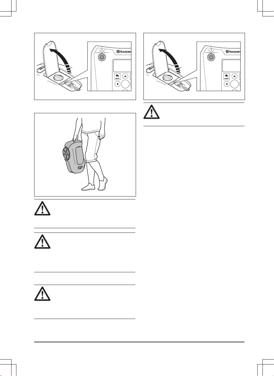
2.3.3 How to lift and move the product
To safely move from or within the work area:
1. Press the
STOP button to stop the product.
If security is set to high level (refer to
To set
the security level on page 23
) the PIN code
has to be entered. The PIN code contains
four digits and is selected when you start the
product for the first time. Refer to
To do the
basic settings on page 21
.
2. Press the ON/OFF button and make sure
the product is turned off. Check that the
indicator lamp on the ON/OFF button is not
lit. This means that the product is disabled.
Refer to
The indicator lamp on page 27
.
12 - Safety 982 - 003 -
OK
OKOK
3. Carry the product by the handle with the
blade disc away from the body.
WARNING: The product must be
turned off before lifting it. The product
is disabled when the indicator lamp on
the ON/OFF button is not lit.
CAUTION: Do not lift the product when
it is parked in the charging station. It
can damage the charging station
and/or the product. Press STOP and
pull the product out of the charging
station before lifting it.
2.3.4 Maintenance
WARNING: The product must be
turned off before any maintenance is
done. The product is disabled when
the indicator lamp on the ON/OFF
button is not lit.
OK
OKOK
CAUTION: Never use a high-pressure
washer to clean the product. Never
use solvents for cleaning.
Inspect the product weekly and replace any
damaged or worn parts. Refer to
Introduction -
maintenance on page 30
.
2.3.5 In the event of a thunderstorm
To reduce the risk of damage to electrical
components in the product and the charging
station, we recommend that all connections to the
charging station are disconnected (power supply,
boundary wire and guide wire) if there is a risk of
a thunderstorm.
1. Mark the wires to simplify reconnecting. The
charging station’s connections are marked
R, L and GUIDE.
2. Disconnect all connected wires and the
power supply.
3. Connect all the wires and the power supply
if there is no longer a risk of thunder. It is
important that each wire is connected to the
right place.
982 - 003 - Safety -
13
3 Installation
3.1 Introduction - Installation
WARNING: Read and understand the
safety chapter before you install the
product.
CAUTION: Use original spare parts
and installation material.
Note: Refer to www.husqvarna.com for more
information about installation.
3.2 Before the installation of the wires
You can select to attach the wires with stakes or
bury them. You can use the 2 procedures for the
same work area.
• Bury the boundary wire or the guide wire if
you are going to use a dethatcher on the
work area. If not, attach the boundary wire
or guide wire with stakes.
• Cut the grass before you install the product.
Make sure that the grass is maximum 4 cm /
1.6 in.
Note: The first weeks after installation the
perceived sound level when cutting the grass
may be higher than expected. When the product
has cut the grass for some time, the perceived
sound level is much lower.
3.3 Before the installation of the
product
• Make a blueprint of the work area and
include all obstacles.
• Make a mark on the blueprint where to put
the charging station, the boundary wire and
the guide wire.
• Make an eyelet on the blueprint where the
guide wire connects to the boundary wire.
Refer to
To install the guide wire on page
19
.
• Fill in holes in the lawn.
Note: Holes with water in the lawn can
cause damage to the product.
3.3.1 To examine where to put the charging
station
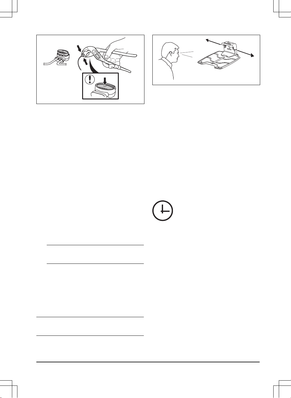
• Keep a minimum 2 m / 6.6 ft. of free space
in front of the charging station.
• Keep a minimum of 30 cm / 12 in. of free
space to the right and left of the center of
the charging station.
60- cm / 24- in.
• Put the charging station near an outdoor
power outlet.
• Put the charging station on a level surface.
Max 5 cm/2"
Max 5 cm /2"
Max +/- 2 cm / 0.8 in.
• Put the charging station in the lowest
possible section of the work area.
14 - Installation 982 - 003 -
• Put the charging station in an area with
protection from the sun.
• If the charging station is installed on an
island, make sure to connect the guide wire
to the island. Refer to
To make an island on
page 17
.
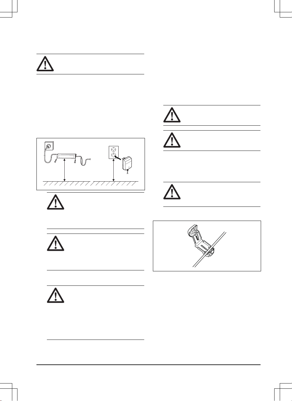
3.3.2 To examine where to put the power
supply
• Put the power supply in an area with a roof
and protection from the sun and rain.
• Put the power supply in an area with good
airflow.
• Use a residual-current device (RCD) when
you connect the power supply to the power
outlet.
WARNING: Do not change the power
supply. Do not cut or extend the low-
voltage cable. There is a risk of
electrical shock.
Low-voltage cables of different lengths are
available as accessories.
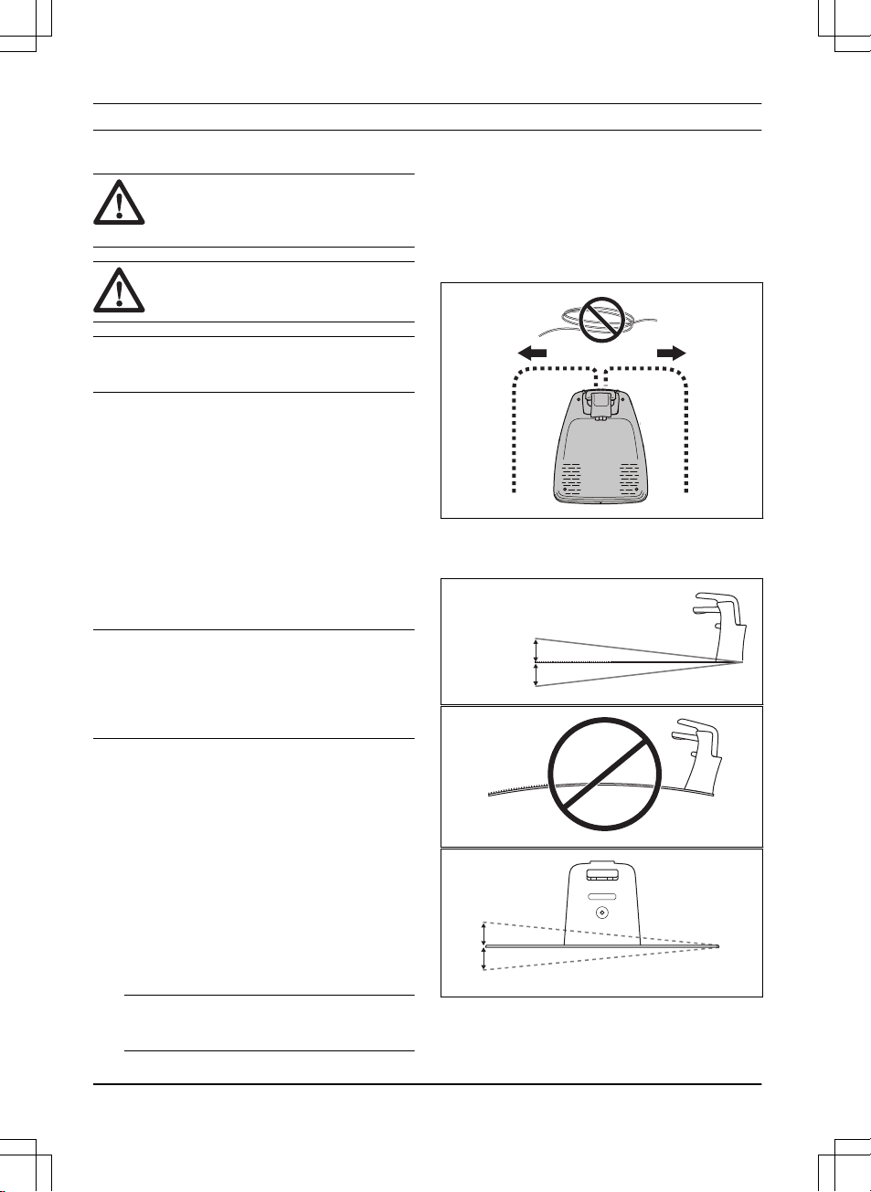
CAUTION: Make sure that the blades
on the product do not cut the low-
voltage cable.
CAUTION: Do not put the low-voltage
cable in a coil or below the charging
station plate. The coil causes
interference with the signal from the
charging station.
3.3.3 To examine where to put the
boundary wire
The boundary wire should be put as a loop
around the work area. Sensors in the product
senses when the product approaches the
boundary wire, and the product selects another
direction.
CAUTION: If the work area is adjacent
to water bodies, slopes, precipices or a
public road, the boundary wire must
have a protective wall. The wall must
be minimum 15 cm / 6 in. in height.
To make the connection easier between the
guide wire and the boundary wire, it is
recommended to make an eyelet where the guide
wire will be connected. Make the eyelet with
approximately 20 cm / 8 in. of the boundary wire.
Note: Make a blueprint of the work area before
you install the boundary wire and guide wire.
982 - 003 - Installation - 15
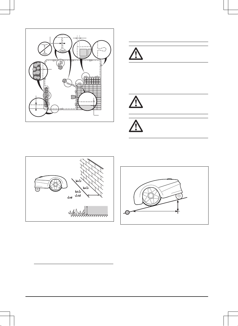
D
E
B
C
F
A
• Put the boundary wire around all of the work
area (A). Adapt the distance between the
boundary wire and obstacles.
• Put the boundary wire 35 cm / 14 in. (B)
from an obstacle that is more than 5 cm / 2
in. high.
35 cm / 14"
> 5 cm/ >2"
• Put the boundary wire 30 cm / 12 in. (C)
from an obstacle that is 1-5 cm / 0.4-2 in.
high.
• Put the boundary wire 10 cm / 4 in. (D) from
an obstacle that is less than 1 cm / 0.4 in.
• If you have a paving stone path that is in
level with the lawn, put the boundary wire
below the paving stone.
Note: If the paving stone is minimum 30 cm /
12 in. wide, use the factory setting for the
Drive Past Wire
function to cut all the grass
adjacent to the paving stone.
CAUTION: Do not let the product
operate on gravel.
• If you make an island, put the boundary wire
that runs to and from the island near
together (E). Put the wires in the same
stake.
• Make an eyelet (F) where the guide wire is
to be connected to the boundary wire.
CAUTION: Do not make sharp
bends when you install the
boundary wire.
CAUTION: For careful operation
without noise, isolate all obstacles
such as trees, roots and stones.
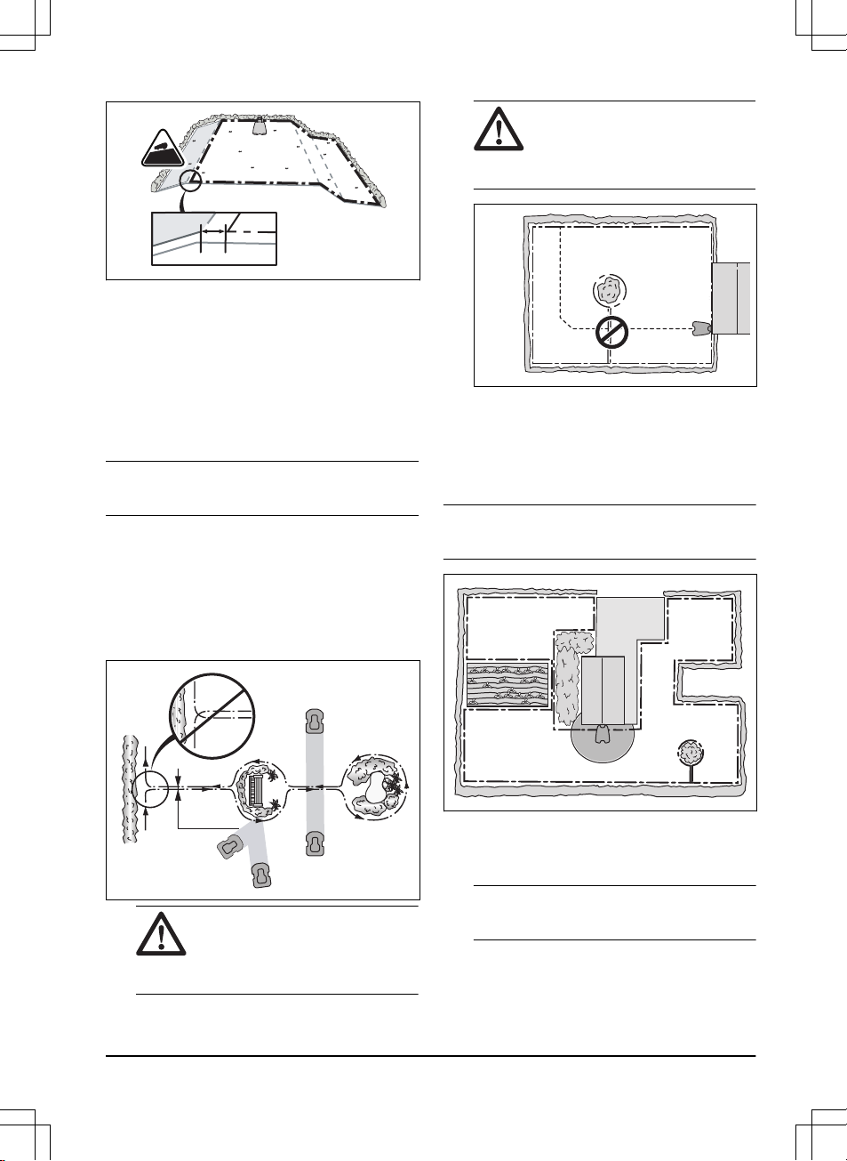
3.3.3.1 To put the boundary wire in a slope
The product can operate in 30% slopes. Slopes
that are too steep must be isolated with the
boundary wire. The gradient (%) is calculated as
height per m. Example: 10 cm / 100 cm = 10%.
10%
10 cm / 3.9"
100 cm / 4 0"
• For slopes steeper than 30% inside the work
area, isolate the slope with boundary wire.
• For slopes steeper than 15% along the outer
edge of the lawn, put the boundary wire 20
cm / 8 in. (A) from the edge.
16 - Installation 982 - 003 -
A
>15%
• Slopes adjacent to a public road must be
isolated with boundary wire. Put a fence or a
protective wall along the outer edge of the
slope.
3.3.3.2 Passages
A passage is a section that has boundary wire on
each side and that connects 2 work areas. The
passage must be a minimum of 60 cm / 24 in.
wide.
Note: If a passage is less than 2 m / 6.5 ft. wide,
install a guide wire through the passage.
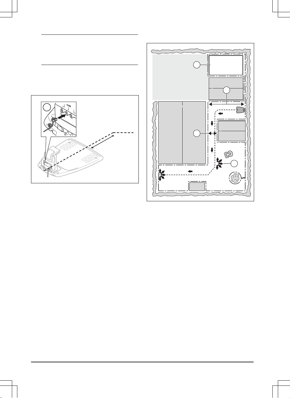
3.3.3.3 To make an island
• Put the boundary wire to and around the
obstacle to make an island.
• Put the 2 sections of boundary wire that run
to and from the obstacle together.
• Put the 2 sections of boundary wire in the
same stake.
0 cm / 0
"
CAUTION: Do not put a section of
boundary wire across the other.
The sections of boundary wire
must be parallel.
CAUTION: Do not put the guide
wire across the boundary wire, for
example a boundary wire that
goes to an island.
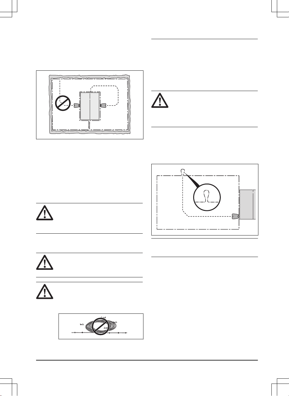
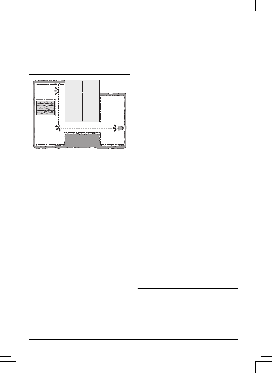
3.3.3.4 To make a secondary area
Make a secondary area (B) if the work area has 2
areas that are not connected with a passage. The
work area with the charging station is the main
area (A).
Note: The product must be manually moved
between the main area and the secondary area.
B
A
• Put the boundary wire around the secondary
area (B) to make an island. Refer to
To
make an island on page 17
.
Note: The boundary wire must be put as 1
loop around all of the work area (A + B).
982 - 003 - Installation - 17
Note: When the product cuts grass in the
secondary area, the
Secondary area
mode
must be selected. Refer to
2nd area on page
28
.
3.3.4 To examine where to put the guide
wire
• Put the guide wire in a line at a minimum of
1 m / 3.3 ft. in front of the charging station.
Min 1m / 3.3ft
G
• Make sure that the guide wire has as much
free area as possible to the left of the guide
wire when facing the charging station. Refer
to
Guide calibration on page 21
.
• Put the guide wire minimum 30 cm / 12 in.
from the boundary wire.
• Do not make sharp bends when you install
the guide wire.
• If the work area has a slope, put the guide
wire diagonally across the slope.
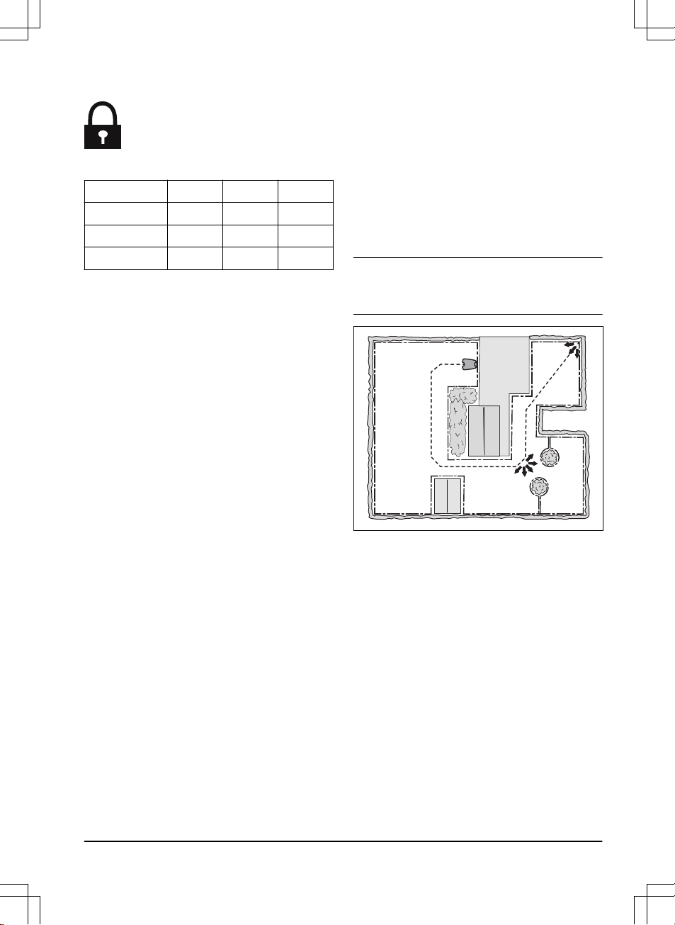
3.3.5 Work area examples
B
D
A
C
• If the charging station is put in a small area
(A), make sure that the distance to the
boundary wire is at a minimum 2 m / 6.6 ft.
• If the work area has a passage (B), make
sure that the distance to the boundary wire
is at a minimum 2 m / 6.5 ft. If the passage is
smaller than 2 m / 6.5 ft., install a guide wire
through the passage. Minimum passage
between the boundary wire is 60 cm / 24 in.
• If the work area has areas which are
connected by a narrow passage (B), you
can set the product to leave the guide wire
after a certain distance (C). The settings can
be changed in
Lawn Coverage
. Refer to
To
set the Lawn Coverage function on page
23
.
• If the work area includes a secondary area
(D), refer to
To make a secondary area on
page 17
. Put the product in the secondary
area and select
Secondary area mode
.
18 - Installation 982 - 003 -
3.4 Installation of the product
3.4.1 To install the charging station
WARNING: Obey national regulations
about electrical safety.
1. Read and understand the instructions about
the charging station. Refer to
To examine
where to put the charging station on page
14
.
2. Put the charging station in the selected area.
3. Connect the low-voltage cable to the
charging station.
4. Put the power supply at a minimum height of
30 cm / 12 in.
min 30 cm / 12”
WARNING: Do not put the power
supply at a height where there is a
risk it can be put in water. Do not
put the power supply on the
ground.
WARNING: Do not encapsulate
the power supply. Condensed
water can harm the power supply
and increase the risk of electrical
shock.
5. Connect the power supply cable to a
100-240V outdoor power outlet.
WARNING: Applicable to USA/
Canada. If power supply is
installed outdoors: Risk of Electric
Shock. Install only to a covered
Class A GFCI receptacle (RCD)
that has an enclosure that is
weatherproof with the attachment
plug cap inserted or removed.
6. Put the low-voltage cable in the ground with
stakes or bury the cable. Refer to
To put the
wire into position with stakes on page 20
or
To bury the boundary wire or the guide wire
on page 20
.
7. Connect the wires to the charging station.
Refer to
To install the boundary wire on
page 19
and
To install the guide wire on
page 19
.
8. Attach the charging station to the ground
with the supplied screws.
CAUTION: Do not make new
holes in the charging station plate.
CAUTION: Do not put your feet on
the charging station.
3.4.2 To install the boundary wire
1. Put the boundary wire around all of the work
area. Start and complete the installation
behind the charging station.
CAUTION: Do not put unwanted
wire in a coil. The coil causes
interference with the product.
2. Open the connector and put the boundary
wire in the connector.
3. Close the connector with a pair of pliers.
4. Cut the boundary wire 1-2 cm / 0.4-0.8 in.
above each connector.
5. Push the right connector onto the metal pin
on the charging station with the mark "R".
6. Push the left connector onto the metal pin
on the charging station with the mark "L".
3.4.3 To install the guide wire
1. Open the connector and put the wire in the
connector.
2. Close the connector with a pair of pliers.
982 - 003 - Installation -
19
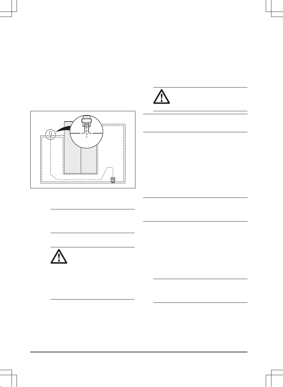
3. Cut the guide wire 1-2 cm / 0.4-0.8 in. above
each connector.
4. Push the guide wire through the slot in the
charging station plate.
5. Push the connector onto the metal pin on
the charging station with the mark "G".
6. Put the end of the guide wire at the eyelet
on the boundary wire.
7. Cut the boundary wire with a pair of wire
cutters.
8. Connect the guide wire to the boundary wire
with a coupler.
a) Put the 2 ends of the boundary wire
and the end of the guide wire into the
coupler.
Note: Make sure that you can see the
end of the guide wire through the
transparent area of the coupler.
b) Push the button on the coupler with an
adjustable pliers.
CAUTION: Twinned cables,
or a screw terminal block that
is insulated with insulation
tape are not satisfactory
splices. Soil moisture will
cause the wire to oxidize and
after a time result in a broken
circuit.
9. Attach the guide wire to the ground with
stakes or bury the guide wire in the ground.
Refer to
To put the wire into position with
stakes on page 20
or
To bury the boundary
wire or the guide wire on page 20
.
3.5 To put the wire into position with
stakes
• Put the boundary wire and the guide wire on
the ground.
• Put the stakes at a maximum of 75 cm / 30
in. distance from each other.
• Attach the stakes to the ground with a
hammer or a plastic mallet.
CAUTION: Make sure that the
stakes hold the boundary wire and
the guide wire against the ground.
Note: The wire is overgrown with grass and not
visible after a few weeks.
3.6 To bury the boundary wire or the
guide wire
• Cut a groove in the ground with an edge
cutter or a straight shovel.
• Put the boundary wire or the guide wire 1-20
cm / 0.4-8 in. into the ground.
3.7 To extend the boundary wire or the
guide wire
Note: Extend the boundary wire or the guide wire
if it is too short for the work area. Use original
spare parts, for example couplers.
1. Cut the boundary wire or the guide wire with
a pair of wire cutters where it is necessary to
install the extension.
2. Add wire where it is necessary to install the
extension.
3. Put the boundary wire or the guide wire into
position.
4. Put the wire ends into a coupler.
Note: Make sure that you can see the ends
of the boundary wire or the guide wire
through the transparent area of the coupler.
5. Push the button on the coupler with an
adjustable pliers.
20 - Installation 982 - 003 -
6. Put the boundary wire or the guide wire into
position with stakes.
3.8 After the installation of the product
3.8.1 To do a visual check of the charging
station
1. Make sure that the indicator LED lamp on
the charging station has a green light.
2. If the indicator LED lamp does not have a
green light, do a check of the installation.
Refer to
Indicator lamp in the charging
station on page 39
and
To install the
charging station on page 19
.
3.8.2 To do the basic settings
Before you start the product for the first time, you
must do the basic settings.
1. Push the
ON/OFF button.
2. Push the arrow buttons and the OK button.
Select
language, country, date, time
and set
a PIN code.
Note: It is not possible to use 0000 as PIN
code.
3. Put the product in the charging station.
4. Push the START button and close the hatch.
3.8.3 Guide calibration
The calibration process sets as wide guide
corridor as possible to reduce the risk of tracks
forming on the lawn. Refer to
To set the starting
point on page 24
.
Note: The product always runs to the left of the
guide wire (as seen facing the charging station).
If the distance on the left side of the starting point
is less than 0.6 m / 2 ft. the calibration process is
interrupted. For the widest possible guide
corridor, make sure that the distance from the
starting point to the boundary wire is minimum
1.35 m / 4.5 ft. (perpendicular to the guide wire).
3.9 To do the product settings
The product has factory settings but the settings
can be adapted to each work area.
3.9.1 To get access to the menu
1. Push the
STOP button.
2. Use the up/down arrow buttons and the OK
button to enter the PIN code.
3. Push the MENU button.
3.9.2 To do the schedule settings
3.9.2.1 Wizard
The wizard is a quick tool to find suitable
schedule settings for your lawn.
1. Enter your estimated lawn size. It is not
possible to enter a larger lawn size than the
maximum work capacity.
2. Push the
OK button to confirm the lawn size.
By entering your lawn size the wizard
suggests either a suitable daily schedule (go
to step 4) or need input for inactive days.
3. Choose what day(s) the product should be
inactive. Use the up/down
arrow buttons to
shift between days.
4. Push the OK button to confirm the chosen
inactive day(s).
5. The wizard suggests a daily schedule for the
active days. If you want to move the
schedule interval to earlier or later in the day
then push the
arrow buttons up or down.
982 - 003 - Installation - 21
6. Push the OK button to confirm the daily
schedule. An overview of the daily schedule
is presented. Push the OK button to go back
to main menu.
Note: To change the schedule settings for
individual work days use the
Schedule -
Advanced
menu.
3.9.2.2 To calculate the schedule setting
1. Calculate the dimension of your lawn in m
2
/
yd
2
.
2. Divide the m
2
/ yd
2
of the lawn with the
approximate operation capacity. Refer to
table below.
3. The result is equal to the number of hours
that the product must operate each day. The
number of hours includes both operation
and charging time.
Note: The operation capacity is approximate and
schedule settings can be adjusted.
Model Approximate operation ca-
pacity, m
2
/ yd
2
/ h
115H 67 / 80
Example: A lawn of 1000 m
2
/ 1200 yd
2
, cut with
a 115H.
1000 m
2
/ 67 ≈ 15 h.
1200 yd
2
/ 80 ≈ 15 h.
Days /
week
h / day Schedule settings
7 15 07:00 - 22:00 / 7 am
- 10 pm
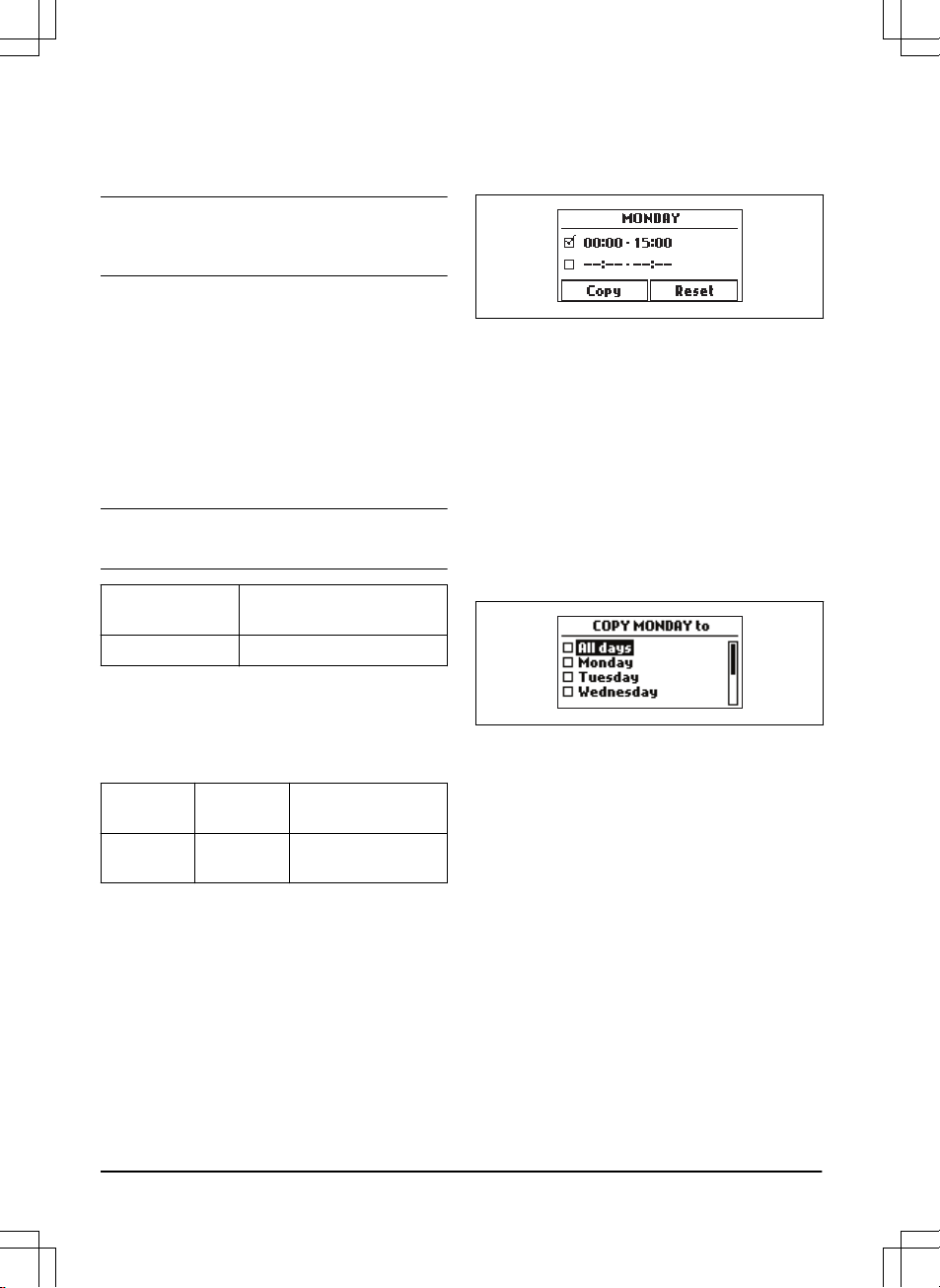
3.9.2.3 To set the schedule
1. Do steps 1–3 in
To get access to the menu
on page 21
.
2. Use the arrow buttons and the OK button to
move through the menu structure
Schedule
> Advanced > Overview
.
3. Use the arrow buttons and the OK button to
select the day.
4. Use the left arrow button to select the
period.
5. Push the
OK button.
6. Enter the time with the arrow buttons. The
product can cut the grass 1 or 2 periods
each day.
7. If the product must not cut grass on a
specified day, unselect the box adjacent to
the 2 time periods.
3.9.2.4 To copy the schedule setting
1. Do steps 1–3 in
To get access to the menu
on page 21
.
2. Use the arrow buttons and the OK button to
move through the menu structure
Schedule
> Advanced > Overview > Copy
.
3. Use the arrow buttons and the OK button to
copy the schedule setting. You can copy the
schedule settings day to day or for the full
week.
3.9.2.5 To reset the schedule setting
You can remove all schedule settings and use
the factory setting.
1. Do steps 1–3 in
To get access to the menu
on page 21
.
2. Use the arrow buttons and the OK button to
move through the menu structure
Schedule
> Advanced > Overview > Reset
.
a) Push the arrow buttons to select
Current day
to only set the current day
to factory settings.
b) Push the arrow buttons to select
All
week
to reset all schedule settings to
factory settings.
3. Push the OK button.
22 - Installation 982 - 003 -
3.9.3 Security level
There are 3 security levels for the product.
Function Low Medium High
Alarm X
PIN-code X X
Time lock X X X
• Alarm - An alarm goes off if the PIN-code is
not entered within 10 seconds after the
STOP button is pushed. The alarm also
goes off when the product is lifted. The
alarm stops when the PIN-code is entered.
• PIN-code - The correct PIN-code must be
entered to get access to the Menu structure
of the product. If the incorrect PIN-code is
entered 5 times, the product is locked for a
time. The lock is extended for each new
incorrect try.
• Time lock - The product locks if the PIN-
code has not been entered in 30 days. Enter
the PIN-code to get access to the product.
3.9.3.1 To set the security level
Select 1 of 3 security levels for your product.
1. Do steps 1–3 in
To get access to the menu
on page 21
.
2. Use the arrow buttons and the OK button to
move through the menu structure
Settings >
Security > Security level
.
3. Use the arrow buttons and the OK button to
select the level of security.
4. Push the
OK button.
3.9.3.2 To change the PIN-code
1. Do steps 1–3 in
To get access to the menu
on page 21
.
2. Use the arrow buttons and the OK button to
move through the menu structure
Settings >
Security > Advanced > Change PIN-code
.
3. Enter the new PIN code.
4. Push the OK button.
5. Enter the new PIN code.
6. Push the
OK button.
7. Make a note of the new PIN code. Refer to
Introduction on page 3
.
3.9.4 Lawn Coverage
The
Lawn Coverage
function is used to guide the
product to remote parts of the work area. If the
work area includes areas that are connected with
narrow passages, the
Lawn Coverage
function is
useful to be able to maintain a well-cut lawn in all
parts of the yard. The product begins to mow
when it reaches the remote area. At all other
times, the product leaves the charging station in
the standard manner and starts to mow.
Note: You can use up to 3 remote areas but the
sum of Proportion for Area 1-3 cannot exceed
100%.
3.9.4.1 To set the Lawn Coverage function
1. Do steps 1–3 in
To get access to the menu
on page 21
.
2. Use the arrow buttons and the OK button to
move through the menu structure
Settings >
Lawn Coverage > Area 1-3
.
3. Use the arrow button to select the area.
4. Push the OK button.
5. Measure the distance from the charging
station to the start of the area. Measure
along the guide wire. Refer to
To measure
the distance from the charging station on
page 24
.
6. Push the arrow buttons to select the
distance, measured in m.
7. Push the
OK button.
982 - 003 - Installation - 23
8. Use the arrow buttons to select the % of the
cutting time the product must cut the area.
The % is equal to the % of the area in
relation to the complete work area.
a) Measure the area.
b) Divide the area with the work area.
c) Convert the result to %.
30%
20%
9. Push the BACK button.
3.9.4.2 To do a test of the Lawn Coverage
function
1. Put the product in the charging station.
2. Do step 1-3 in
To get access to the menu on
page 21
.
3. Use the arrow buttons and the OK button to
move through the menu structure
Settings >
Lawn Coverage > Area 1-3 > More > Test
.
4. Push the OK button.
5. Push the START button.
6. Close the hatch.
7. Make sure the product can find the area.
3.9.4.3 To measure the distance from the
charging station
1. Put the product in the charging station.
2. Do steps 1–3 in
To get access to the menu
on page 21
.
3. Use the arrow buttons and the OK button to
move through the menu structure
Settings >
Lawn Coverage > Area 1-3 > How far?
4. Use the arrow buttons to set 500 m as a
distance.
5. Push the OK button.
6. Use the arrow buttons and the OK button to
move through the menu structure
Settings >
Lawn Coverage > Area 1-3 > More > Test
.
7. Push the OK button.
8. Push the STOP button when the product is
at the distance you select to measure. The
distance shows in the display.
3.9.4.4 To disable or enable the Lawn Coverage
function
Disable or enable the
Lawn Coverage
function for
each area.
1. Do steps 1–3 in
To get access to the menu
on page 21
.
2. Use the arrow buttons and the OK button to
move through the menu structure
Settings >
Lawn Coverage > Area 1-3 > Disable
.
3. Push the OK button.
4. Push the BACK button.
3.9.4.5 To reset the Lawn Coverage settings
You can reset the
Lawn Coverage
settings for
each area and use the factory setting.
1. Do steps 1–3 in
To get access to the menu
on page 21
.
2. Use the arrow buttons and the OK button to
move through the menu structure
Settings >
Lawn Coverage > Area 1-3 > More > Reset
.
3. Push the OK button.
3.9.5 To set the starting point
This function allows you to control how far the
product drives along the guide wire from the
charging station before it starts operating. The
factory setting is 60 cm and the maximum
distance is 300 cm.
Note: This is a useful function if the charging
station is placed below a veranda or in another
limited space area. If the charging station is
placed in an open area, the factory setting can be
used. Choosing a good starting point is important
so that the guide calibration process is optimized.
1. Do steps 1-3 in
To get access to the menu
on page 21
.
2. Use the arrow button and the OK button to
move through the menu structure
Settings >
Installation > Starting point
.
24 - Installation 982 - 003 -

3. Use the arrow buttons to specify the
distance in cm.
4. Push the BACK button.
3.9.6 To set the Drive Past Wire function
The front of the product always moves past the
boundary wire by a specified distance before the
product moves back into the work area. The
factory setting is 32 cm. You can select a
distance of 20-30 cm.
1. Do steps 1–3 in
To get access to the menu
on page 21
.
2. Use the arrow button and the OK button to
move through the menu structure
Settings >
Installation > Drive Past Wire
.
3. Use the arrow buttons to set the distance in
cm.
4. Push the BACK button.
3.9.7 ECO mode
ECO mode
stops the signal in the boundary loop,
the guide wire and the charging station, when the
product is parked or is charging.
Note: Use
ECO mode
to save energy and avoid
interference with other equipment, for example
hearing loops or garage doors.
Note: Push the STOP button before you remove
the product from the charging station. If not, the
product can not be started in the work area.
3.9.7.1 To set the ECO mode
1. Do steps 1–3 in
To get access to the menu
on page 21
.
2. Use the arrow buttons and the OK button to
move through the menu structure
Settings >
Installation > ECO mode
.
3. Push the OK button to select the
ECO
mode
.
4. Push the BACK button.
3.9.8 To avoid collisions with the mower
house
If you have installed a mower house (accessory),
the wear on the product and the mower house
decreases when you select
Avoid house
collisions
.
1. Do steps 1–3 in
To get access to the menu
on page 21
.
2. Use the arrow buttons and the OK button to
move through the menu structure
Settings >
Installation > Mower house > Avoid house
collisions
.
3. Push the BACK button.
Note: If
Avoid house collisions
is selected it can
result in grass that is not cut around the charging
station.
3.9.9 Automower
®
Connect@Home
The product can connect to mobile devices that
have the Automower
®
Connect app installed.
Automower
®
Connect is a free app for your
mobile device. The short-range interaction with
the product is called Automower
®
Connect@Home. When pairing between the
product and app has been confirmed, you have
access to the menus and functions as long as
you are within short-range (Bluetooth
®
).
3.9.9.1 To install the Automower
®
Connect app
1. Download the Automower
®
Connect app on
your mobile device.
2. Register in the Automower
®
Connect app.
3. Log in to your Husqvarna account in the
Automower
®
Connect app.
3.9.9.2 To pair Automower
®
Connect and the
product
1. Do steps 1–3 in
To get access to the menu
on page 21
.
2. Use the arrow buttons and the OK button to
move through the menu structure
Settings >
Installation > Connect@Home > New
pairing
.
3. Select
My mowers
in the Automower
®
Connect app.
4. Select the plus sign (+).
5. Follow the instructions in the app.
3.9.10 General
In
General
you can change the general settings
of the product.
3.9.10.1 To set the time & date
1. Do steps 1–3 in
To get access to the menu
on page 21
.
982 - 003 - Installation -
25

2. Use the arrow buttons and the OK button to
move through the menu structure
Settings >
General > Time & Date
.
3. Use the arrow buttons to set the time and
then push the BACK button.
4. Use the arrow buttons to set the date and
then push the BACK button.
5. Use the arrow buttons to set the time format
and then push the BACK button.
6. Use the
arrow buttons to set the date format
and then push the BACK button.
3.9.10.2 To set the language
1. Do steps 1–3 in
To get access to the menu
on page 21
.
2. Use the arrow buttons and the OK button to
move through the menu structure
Settings >
General > Language.
3. Use the arrow buttons to select language
and then push the BACK button.
3.9.10.3 To set the country
1. Do steps 1–3 in
To get access to the menu
on page 21
.
2. Use the arrow buttons and the OK button to
move through the menu structure
Settings >
General > Country.
3. Use the arrow buttons to select country and
then push the BACK button.
3.9.10.4 To reset all user settings
1. Do steps 1–3 in
To get access to the menu
on page 21
.
2. Use the arrow buttons and the OK button to
move through the menu structure
Settings >
General > Reset all user settings
.
3. Use the right arrow button to select
Proceed
with reset of all user settings?
4. Push the OK button to reset all the user
settings.
Note:
Security level, PIN code, Loop signal,
Messages, Date & Time, Language
and
Country
settings
are not reset.
3.9.10.5 The About menu
The
About
menu displays information about the
product, for example serial number and firmware
versions.
26 - Installation 982 - 003 -
4 Operation
4.1 The ON/OFF button
WARNING: Read the safety
instructions carefully before you start
the product.
WARNING: Keep your hands and feet
away from the rotating blades. Never
put your hands or feet close to or
under the machine when the motor is
running.
WARNING: Do not use the product
when persons, especially children, or
animals, are in the work area.
OK
OKOK
• Press the ON/OFF button to turn the product
on. The product is active when the indicator
lamp on the
ON/OFF button is lit.
• Press the ON/OFF button to turn the product
off.
4.1.1 The indicator lamp
The indicator lamp on the
ON/OFF button is an
important status indicator:
• The product is active if the indicator lamp
lights continuously.
• The product is in standby if the indicator
lamp flashes. This means that the operator
must press the ON/OFF button to make the
product active again.
• The product is disabled when the indicator
lamp is not lit.
WARNING: It is only safe to carry out
inspection or maintenance on the
product when the product is disabled.
The product is disabled when the lamp
on the ON/OFF button is not lit.
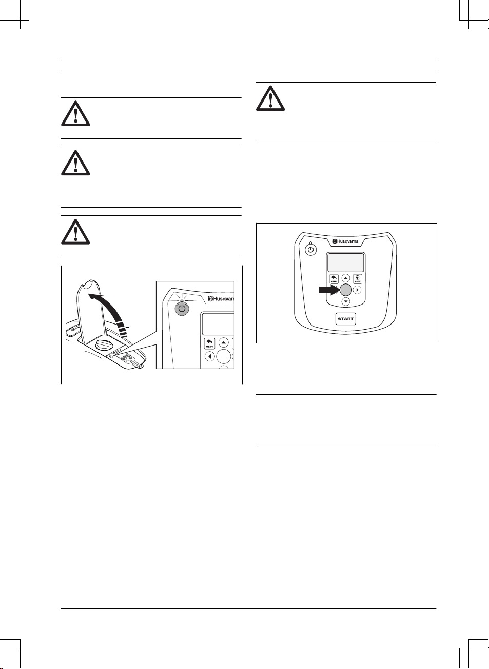
4.2 To start the product
1. Open the hatch to the keypad.
2. Push the ON/OFF button. The display is lit
up.
3. Use the up/down arrow buttons and the OK
button to enter the PIN code.
OK
4. Select the desired operating mode and
confirm with the OK button. Refer to
Operating modes on page 27
.
5. Close the hatch.
Note: If the product is parked in the charging
station, the product will only leave the charging
station when the battery is fully charged and if the
schedule allows the product to operate.
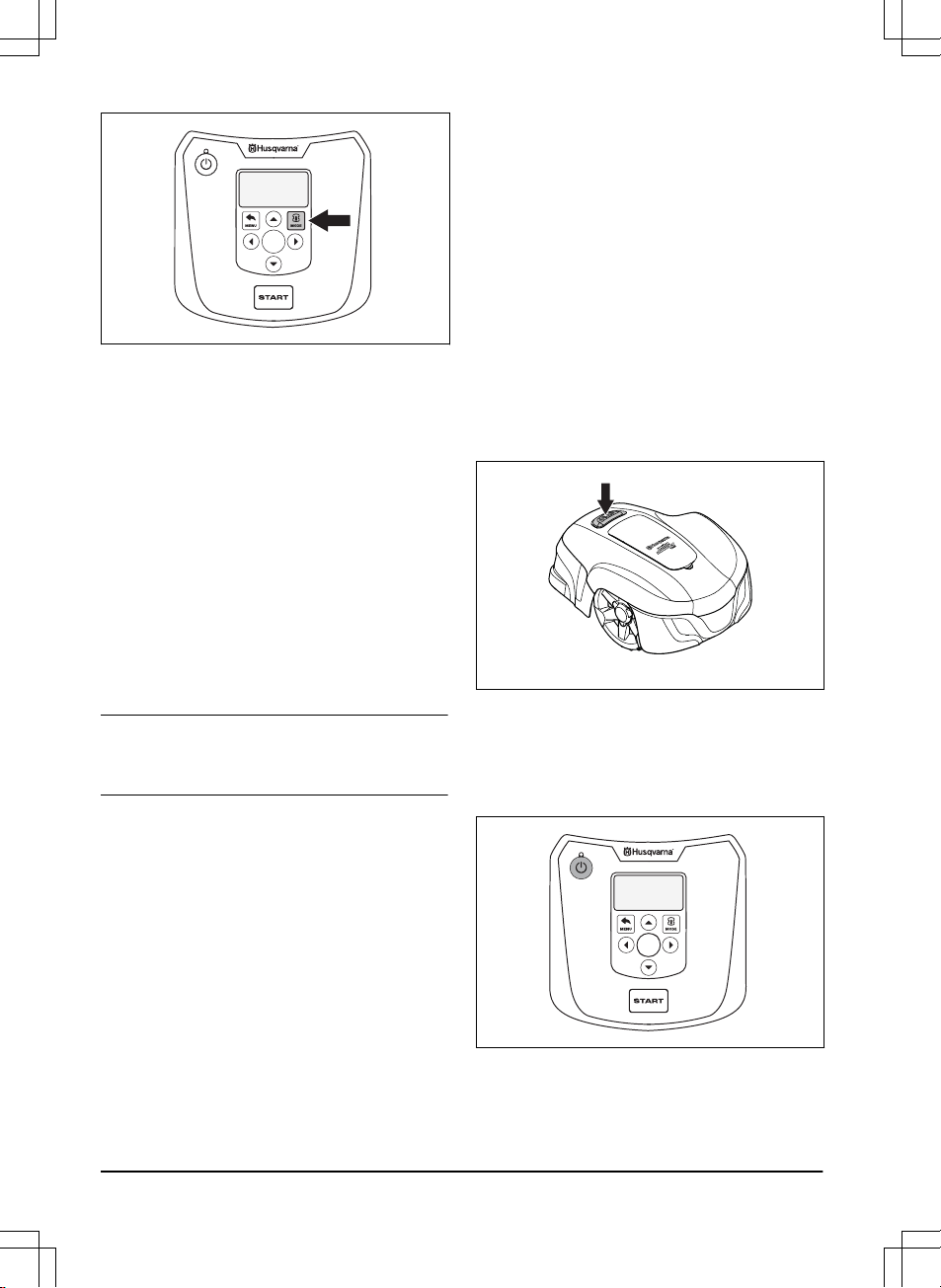
4.3 Operating modes
When the
Mode button is pressed the following
operating modes can be selected:
• Main area
• Secondary area (2nd area)
• Park
• Park / Schedule
• Override schedule
• Spot cutting
982 - 003 - Operation -
27
OK
4.3.1 Main area
Main area
is the standard operating mode where
the product mows and charges automatically.
4.3.2 2nd area
To mow secondary areas the operating mode
2nd area
must be chosen. In the
2nd area
mode,
the operator must move the product manually
between the main area and the secondary area.
The product mows until the battery is empty.
When the battery is empty, the product stops and
the message
Needs manual charging
shows in
the product display. Put the product in the
charging station to charge the battery. When the
battery is charged, the product moves out of the
charging station and stops. The product is now
prepared to start operation, but needs
confirmation from the operator first.
Note: If you want to cut the main area after the
battery is charged, set the product to
Main area
mode before placing it in the charging station.
4.3.3 Park
Operating mode
Park
means that the product
remains in the charging station until a different
operating mode is selected.
4.3.4 Park / Schedule
Operating mode Park / Schedule
means that the
product remains in the charging station until the
next schedule or standby permits operation.
Refer to
To set the schedule on page 22
.
4.3.5 Override schedule
The schedule settings can be temporarily
overridden by selecting
Override schedule
. It is
possible to override the schedule for 3 h. It is not
possible to override a standby period.
4.3.6 Spot cutting
The
Spot cutting
function is activated with the
START button and is useful for quickly mowing
an area where the grass has been mown less
than in other parts of the yard. You must
manually move the product to the chosen area.
Spot cutting means that the product mows in a
spiral pattern in order to cut the grass in the area
where it was started. When this is done, the
product automatically switches back to
Main area
or
Secondary area
.
4.4 To stop the product
1. Press the STOP button on top of the
product.
The product stops and the blade motor stops.
4.5 Switch off
1. Press the STOP button.
2. Open the hatch.
3. Press the ON/OFF button for 3 seconds.
OK
4. The product shuts down.
5. Check that the indicator lamp on the
ON/OFF button is not lit.
28 - Operation 982 - 003 -
4.6 To charge the battery
When the product is new or has been stored for a
long period, the battery can be empty and needs
to be charged before starting. In the
Main area
mode, the product automatically alternates
between mowing and charging.
WARNING: Only charge the product
using a charging station which is
intended for it. Incorrect use may result
in electric shock, overheating or
leakage of corrosive liquid from the
battery.
In the event of leakage of electrolyte
flush with water and seek medical help
if it comes in contact with the eyes etc.
1. Press the ON/OFF button to start the
product.
2. Place the product in the charging station.
Slide the product in as far as possible to
ensure proper contact between the product
and the charging station. Refer to contact
and charging strips in
Product overview on
page 4
3. The display shows a message that charging
is in progress.
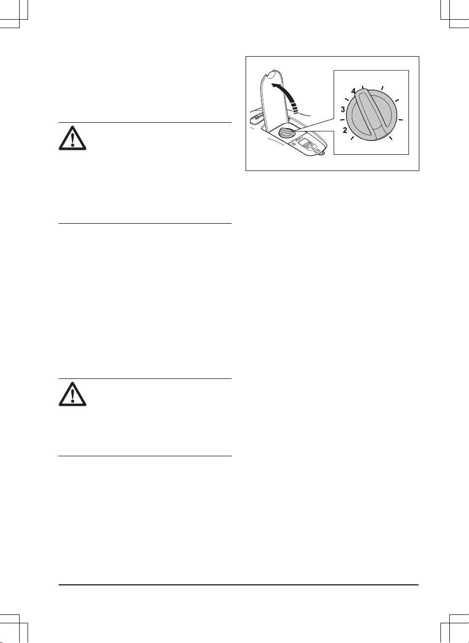
4.7 Adjust the cutting height
The cutting height can be varied from MIN (5 cm /
2 in.) to MAX (9 cm / 3.6 in.).
CAUTION: During the first weeks after
a new installation, the cutting height
must be set to MAX to avoid damaging
the loop wire. After this, the cutting
height can be lowered step by step
every week until the desired cutting
height has been reached.
4.7.1 To adjust the cutting height
1. Press the STOP button to stop the product.
2. Open the hatch.
OK
6
5
7
8
3. Turn the knob to the required position.
• Turn clockwise to increase the cutting
height.
• Turn counter-clockwise to decrease the
cutting height.
4. Close the hatch.
982 - 003 - Operation -
29
5 Maintenance
5.1 Introduction - maintenance
For better operating reliability and longer service
life: check and clean the product regularly and
replace worn parts if necessary. All maintenance
and servicing must be done according to
Husqvarna's instructions. Refer to
Warranty
terms on page 48
.
When the product is first used, the blade disc and
blades should be inspected once a week. If the
amount of wear during this period has been low,
the inspection interval can be increased.
It is important that the blade disc rotates easily.
The edges of the blades should not be damaged.
The lifetime of the blades varies immensely and
depends for instance on:
• Operating time and size of the work area.
• Type of grass and seasonal growth.
• Soil, sand and use of fertilizers.
• The presence of objects such as cones,
windfalls, toys, tools, stones, roots and the
like.
The normal life is 4 to 7 weeks when used under
favorable conditions. Refer to
To replace the
blades on page 31
on how to replace the
blades.
Note: Working with blunt blades gives a poorer
mowing result. The grass is not cut cleanly and
more energy is needed resulting in the product
not mowing such a large area.
WARNING: The product must be
turned off before any maintenance is
done. The product is disabled when
the indicator lamp on the ON/OFF
button is not lit.
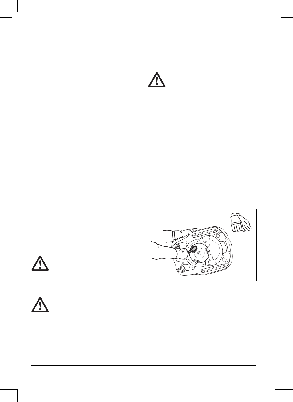
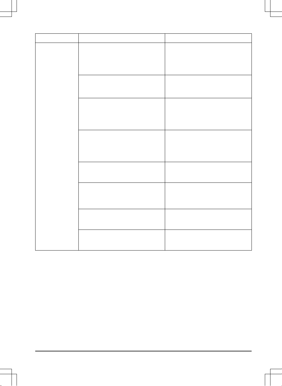
WARNING: Wear protective gloves.
5.2 Clean the product
It is important to keep the product clean. A
product with large amounts of grass stuck to it
will not cope as well with slopes. It is
recommended to clean using a brush.
Husqvarna offers a special cleaning and
maintenance kit as an accessory. Contact your
Husqvarna central service.
CAUTION: Never use a high-pressure
washer to clean the product. Never
use solvents for cleaning.
5.2.1 Chassis and blade disc
Inspect the blade disc and blades once a week.
1. Press the
STOP button.
2. Press the ON/OFF button for 3 seconds to
turn off the product.
3. Check that the indicator lamp on the
ON/OFF button is not lit.
4. If the product is very dirty, clean it by using a
dish brush or a garden hose. Do not use a
high-pressure washer.
5. Lift the product onto its side.
6. Clean the blade disc and chassis using for
example a dish brush. At the same time,
check that the blade disc rotates freely in
relation to the foot guard. Also, check that
the blades are intact and can pivot freely.
5.2.2 Wheels
Clean around the front wheels and rear wheel as
well as the rear wheel bracket. Grass on the
wheels can impact on how the product performs
in slopes.
5.2.3 Cover
Use a damp, soft sponge or cloth to clean the
cover. If the cover is very dirty it may be
necessary to use a soap solution or washing-up
liquid.
30 - Maintenance 982 - 003 -
5.2.4 Charging station
Clean the charging station regularly from grass,
leaves, twigs and other objects that may impede
docking.
WARNING: Use the plug to disconnect
the charging station before any
maintenance, or cleaning of charging
station or power supply.
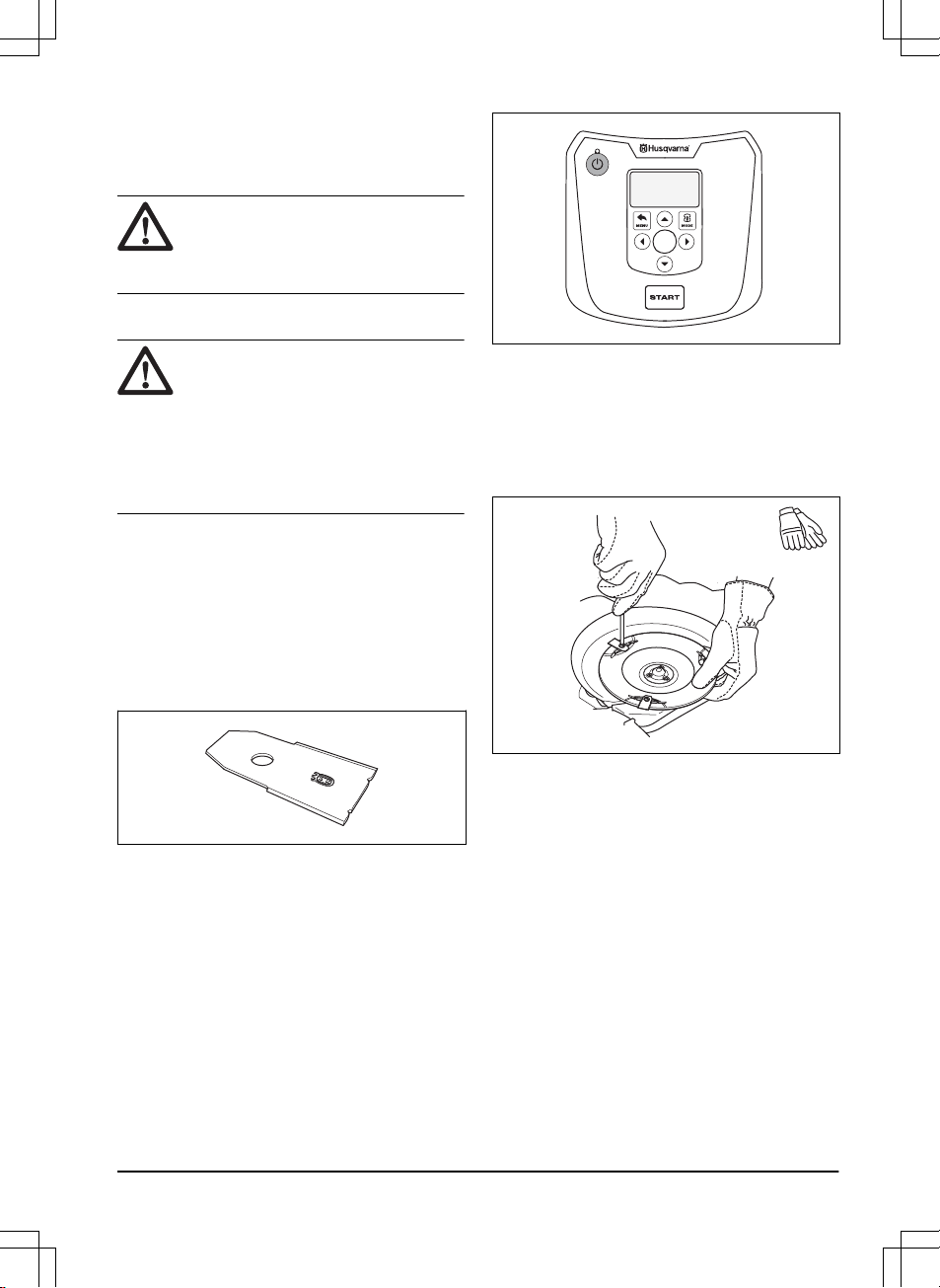
5.3 Replace the blades
WARNING: Use blades and screws of
the right type. Husqvarna can only
guarantee safety when using original
blades. Only replacing the blades and
reusing the screw can result in a screw
wearing during mowing. The blades
can then be propelled from under the
body and cause serious injury.
Replace worn or damaged parts for safety
reasons. Even if the blades are intact, they
should be replaced on a regular basis for the best
mowing result and low energy usage. All 3 blades
and screws must be replaced at the same time to
obtain a balanced cutting system. Use
Husqvarna original blades embossed with the
crowned H-mark logotype, refer to
Warranty
terms on page 48
.
5.3.1 To replace the blades
1. Press the STOP button.
2. Open the hatch.
3. Press the ON/OFF button for 3 seconds to
turn off the product.
OK
4. Check that the indicator lamp on the
ON/OFF button is not lit.
5. Turn the product upside down. Place the
product on a soft and clean surface to avoid
scratching the body and the hatch.
6. Remove the 3 screws. Use a straight slot or
cross-tip screwdriver.
7. Remove each blade and screw.
8. Fasten new blades and screws.
9. Check that the blades can pivot freely.
5.4 Firmware update
If service is done by Husqvarna customer service
then available firmware updates are downloaded
to the product by the service technician. Owners
of Husqvarna products can update the firmware if
this is initiated by Husqvarna. Registered users
are in that case notified.
982 - 003 - Maintenance -
31

5.5 Battery
WARNING: Only charge the product
using a charging station which is
intended for it. Incorrect use may result
in electric shock, overheating or
leakage of corrosive liquid from the
battery. In the event of leakage of
electrolyte flush with water and seek
medical help if it comes in contact with
the eyes etc.
WARNING: Use only original batteries
recommended by the manufacturer.
Product safety cannot be guaranteed
with other batteries. Do not use non-
rechargeable batteries.
CAUTION: The battery must be
charged fully before winter storage. If
the battery is not fully charged it can
be damaged and in certain cases be
rendered useless.
If the operating times for the product are shorter
than normal between charges, this indicates that
the battery is getting old and eventually needs
replacing.
Note: Battery life is dependent on the length of
the season and how many hours a day the
product is operating. A long season or many
hours of use a day means that the battery must
be replaced more regularly. The battery is fine as
long as the product maintains a well-cut lawn.
5.5.1 To replace the battery
WARNING: Use only original batteries
recommended by the manufacturer.
Product safety cannot be guaranteed
with other batteries. Do not use non-
rechargeable batteries. The appliance
must be disconnected from the supply
mains when removing the battery.
1. Press the ON/OFF button for 3 seconds to
turn off the product. Check that the indicator
lamp on the
ON/OFF button is not lit.
2. Set the cutting height to MIN.
3. Turn the product upside down. Place the
product on a soft and clean surface to avoid
scratching the body and the display cover.
4. Clean around the battery cover.
5. Unscrew the screws to the battery cover
(Torx 20) and remove the battery cover.
6. Release the latch of the connector and pull it
upwards.
CAUTION: Do not pull the cables.
7. Release the latch of the battery holder and
lift up the battery holder (including the
battery) from the product. If the new battery
is encapsulated in a hard plastic shell, go to
number 10.
Th
i
s
side down
7
7
8
6
8. Release the latch of the battery and lift up
the battery from the battery holder.
9. Place the new battery into the battery
holder.
Note: The sticker "This side down" must be
facing up when you place it into position.
This means that "This side down" will be
facing downwards when the product is
standing on its wheels.
32 - Maintenance 982 - 003 -

10. Place the battery holder (including the
battery) back into place in the product.
11. Connect the cable
12. Fit the battery cover without clamping the
cables. If the seal on the battery cover is
visibly damaged, the entire battery cover
must be replaced.
13. Carefully cross-tighten the 4 screws for the
battery cover (Torx 20).
5.6 Winter service
Take your product to your local Husqvarna
representative for service prior to winter storage.
Regular winter service will maintain the product in
good condition and create the best conditions for
a new season without any disruptions.
Service usually includes the following:
• Thorough cleaning of the body, the chassis,
the blade disc and all other moving parts.
• Testing of the products’s function and
components.
• Checking and, if required, replacing wear
items such as blades and bearings.
• Testing the products’s battery capacity as
well as a recommendation to replace battery
if necessary.
• If new firmware is available, the product is
updated.
982 - 003 - Maintenance -
33

6 Troubleshooting
6.1 Introduction - troubleshooting
In this chapter, faults and symptoms are described and can guide you if the product does not operate
as expected. More suggestions for steps to take in the event of malfunction or symptoms can be found
on www.husqvarna.com.
6.2 Fault messages
Below a number of fault messages are listed which may be shown in the display of the product.
Contact Husqvarna customer service if the same message appears often.
Message Cause Action
Wheel motor
blocked, left/right
Grass or other object has wrapped
around the drive wheel.
Check the drive wheel and remove the
grass or other object.
Cutting system
blocked
Grass or other object has wrapped
around the blade disc.
Check the drive wheel and remove the
grass or other object.
The blade disc lies in a pool of water. Move the product and prevent the col-
lection of water in the work area.
Trapped
The product has got caught in some-
thing.
Free the product and rectify the reason
for it becoming trapped.
The product is stuck behind a number
of obstacles.
Check if there are any obstacles which
make it hard for the product to move on
from this location.
Outside working
area
The boundary wire connections to the
charging station are crossed.
Check that the boundary wire is con-
nected correctly.
The boundary wire is too close to the
edge of the work area.
Check that the boundary wire has been
laid according to the instructions. Refer
to
To install the boundary wire on page
19
.
The work area slopes too much by the
boundary loop.
The boundary wire is laid in the wrong
direction around an island.
Disturbances from metal objects (fen-
ces, reinforcement steel) or buried ca-
bles close by.
Try moving the boundary wire.
The product finds it hard to distinguish
the signal from another product installa-
tion close by.
Place the product in the charging sta-
tion and generate a new loop signal.
34 - Troubleshooting 982 - 003 -

Message Cause Action
Empty battery
The product cannot find the charging
station.
Check that the charging station and the
guide wire are installed in accordance
with the instructions. Refer to
To install
the guide wire on page 19
.
The guide wire is broken or not connec-
ted.
Find out where the break is and rectify
it.
The battery is spent. Replace the battery. Refer to
Battery
on page 32
.
The charging station’s antenna is de-
fective.
Check if the indicator lamp in the
charging station flashes red. Refer to
Indicator lamp in the charging station
on page 39
.
Wrong PIN code
Wrong PIN code has been entered.
Five attempts are permitted, and the
keypad is then blocked for five minutes.
Enter the correct PIN code. Contact
Husqvarna customer service if you for-
get the PIN code.
No drive
The product has got caught in some-
thing.
Free the product and rectify the reason
for the lack of drive. If it is due to wet
grass, wait until the lawn has dried be-
fore using the product.
The work area includes a steep slope. Steep slopes should be isolated. Refer
to
To examine where to put the guide
wire on page 18
.
The guide wire is not laid at an angle
on a slope.
If the guide wire is laid on a slope, it
must be laid at an angle across the
slope. Refer to
To examine where to
put the guide wire on page 18
.
Wheel motor over-
loaded, right/left
The product has got caught in some-
thing.
Free the product and rectify the reason
for the lack of drive. If it is due to wet
grass, wait until the lawn has dried be-
fore using the product.
Charging station
blocked
The contact between the charging
strips and contact strips may be poor
and the product has made a number of
attempts to charge.
Put the product in the charging station
and check that the charging strips and
contact strips make good contact.
An object is obstructing the product. Remove the object.
The charging station is tilted or bent. Confirm that the charging station is
placed on a fully flat and horizontal
ground. The charging station must not
be tilted or bent.
Stuck in charging
station
There is an object in the way of the
product preventing it from leaving the
charging station.
Remove the object.
982 - 003 - Troubleshooting - 35

Message Cause Action
Upside down
The product is leaning too much or has
turned over.
Turn the product the right way up.
Needs manual
charging
The product is set to the
Secondary
area
operating mode.
Place the product in the charging sta-
tion. This behavior is normal and no ac-
tion is required.
Next start hh:mm
The timer setting prevents the product
from operating.
Change the timer settings. Refer to
To
do the schedule settings on page 21
.
The rest period is in progress. The
product has an inbuilt standby period
according to the Standby time table.
This behavior is normal and no action
is required.
The clock on the product is not correct. Set the time. Refer to
To set the time &
date on page 25
.
Today's mowing
completed
The rest period is in progress. The
product has an inbuilt standby period
according to the Standby time table.
This behavior is normal and no action
is required.
Lifted
The lift sensor has been activated as
the product has become trapped.
Free the product.
Wheel drive prob-
lem, right/left
Grass or other object is wrapped
around the drive wheel.
Clean the wheels and around the
wheels.
Safety function
faulty
Temporary electronic or firmware rela-
ted issue in the product.
Restart the product.
If the problem remains, the message
requires action by authorized service
technician.
Electronic problem
Loop sensor prob-
lem, front/rear
Charging system
problem
Tilt sensor prob-
lem
Temporary prob-
lem
Temporary battery
problem
Temporary battery or firmware related
issue in the product.
Restart the product.
Disconnect and reconnect the battery.
If the problem remains, the message
requires action by authorized service
technician.
Battery problem
Charging current
too high
Wrong or faulty power supply unit. Restart the product.
If the problem remains, the message
requires action by authorized service
technician.
36 - Troubleshooting 982 - 003 -
Message Cause Action
No loop signal
The power supply is not connected. Check the wall socket connection and
whether an earth-fault breaker has trip-
ped or not. Check that the low voltage
cable is connected to the charging sta-
tion.
The low voltage cable is damaged or
not connected.
Check that the low voltage cable is not
damaged. Check that it is also properly
connected to the charging station and
to the power supply.
The boundary wire is not connected to
the charging station.
Check that the boundary wire connec-
tors are fitted properly to the charging
station. Replace connectors if dam-
aged. Refer to
To install the boundary
wire on page 19
.
Boundary wire broken. Find out where the break is. Replace
the damaged section of the loop with a
new loop wire and splice using an origi-
nal coupler. Refer to
Find breaks in the
loop wire on page 41
.
ECO mode
is activated and the product
has attempted to start outside the
charging station.
Place the product in the charging sta-
tion and press the
STOP button. Refer
to
ECO mode on page 25
.
The boundary wire is crossed on its
way to and from an island.
Check that the boundary wire is laid ac-
cording to instructions, e.g. in the right
direction around the island. Refer to
To
install the boundary wire on page 19
.
The connection between the product
and the charging station has been bro-
ken.
Place the product in the charging sta-
tion and generate a new loop signal.
Disturbances from metal objects (fen-
ces, reinforcement steel) or buried ca-
bles close by.
Try moving the boundary wire.
982 - 003 - Troubleshooting - 37

6.3 Information messages
Below a number of information messages are listed which may be shown in the display of the product.
Contact Husqvarna customer service if the same message appears often.
Message Cause Action
Low battery
The product cannot find the charging
station.
Check that the charging station and the
guide wire are installed in accordance
with the instructions. Refer to
To install
the guide wire on page 19
.
The guide wire is broken or not connec-
ted.
Find out where the break is and rectify
it.
The battery is spent. Replace the battery. Refer to
Battery
on page 32
.
The charging station’s antenna is de-
fective.
Check if the indicator lamp in the
charging station flashes red. Refer to
Indicator lamp in the charging station
on page 39
.
Settings restored
Confirmation that a
Reset all user set-
tings
has been carried out.
This is normal. No action required.
Guide not found
The guide wire is not connected to the
charging station.
Check that the guide wire connector is
tightly connected to the charging sta-
tion. Refer to
To install the guide wire
on page 19
.
Break in the guide wire. Find out where the break is. Replace
the damaged section of the guide wire
with a new loop wire and splice using
an original coupler.
The guide wire is not connected to the
boundary loop.
Check that the guide wire is connected
correctly to the boundary loop. Refer to
To install the guide wire on page 19
.
Guide calibration
failed
The product has failed to calibrate the
guide wire.
Check that the guide wire is installed
according to the instructions. Refer to
To install the guide wire on page 19
. Al-
so, check that the minimum distance to
the left of the guide wire is met. Refer
to
To examine where to put the guide
wire on page 18
.
Guide calibration
accomplished
The product has succeeded to calibrate
the guide wire.
No action required.
38 - Troubleshooting 982 - 003 -

6.4 Indicator lamp in the charging
station
For a fully functional installation, the indicator lamp in the charging station must emit a solid or flashing
green light. If something else appears, follow the troubleshooting guide below.
There is more help on www.husqvarna.com. If you still need help, please contact Husqvarna customer
service.
Light Cause Action
Solid green light
Good signals No action required
Green flashing
light
The signals are good and
ECO mode
is
activated.
No action required. For more informa-
tion on
ECO mode
. Refer to
ECO mode
on page 25
.
Blue flashing light
The boundary loop is not connected to
the charging station.
Check that the boundary wire connec-
tors are fitted properly to the charging
station. Refer to
To install the guide
wire on page 19
.
Break in the boundary loop. Find out where the break is. Replace
the damaged section of the loop with a
new loop wire and splice using an origi-
nal coupler.
Yellow flashing
light
The guide wire is not connected to the
charging station.
Check that the guide wire connector is
properly connected to the charging sta-
tion. Refer to
To install the guide wire
on page 19
Break in the guide wire. Find out where the break is. Replace
the damaged section of the guide wire
with a new loop wire and splice using
an original coupler.
Red flashing light
Interruption in the charging station’s an-
tenna.
Contact Husqvarna customer service.
Solid red light
Fault in the circuit board or incorrect
power supply in the charging station.
The fault should be rectified by an au-
thorized service technician.
Contact Husqvarna customer service.
982 - 003 - Troubleshooting - 39

6.5 Symptoms
If your product does not work as expected, follow the symptoms guide below.
There is a FAQ (Frequently Asked Questions) on www.husqvarna.com which provides more detailed
answers to a number of standard questions. Contact Husqvarna customer service if you still cannot find
the reason for the fault.
Symptoms Cause Action
The product has
difficulty docking.
The guide wire is not laid in a long
straight line that is far enough out from
the charging station.
Check that the charging station has
been installed according to the instruc-
tions in
To install the charging station
on page 19
The guide wire is not inserted in the
slot under the charging station.
It is absolutely critical for operation that
the guide wire is perfectly straight and
is in the correct position under the
charging station. Therefore make sure
that the guide wire is always in its slot
in the charging station. Refer to
To in-
stall the guide wire on page 19
.
The charging station is on a slope. Place the charging station on a surface
that is entirely level. Refer to
To exam-
ine where to put the charging station on
page 14
.
The product runs
at the wrong time
The product clock needs to be set. Set the clock. Refer to
To set the time
& date on page 25
.
The start and stop times for mowing
are incorrect.
Reset the start time and stop time set-
tings for mowing. Refer to
To reset the
schedule setting on page 22
.
The product vi-
brates.
Damaged blades lead to imbalance in
the cutting system.
Inspect the blades and screws and re-
place them if necessary. Refer to
To re-
place the blades on page 31
.
Too many blades in the same position
lead to imbalance in the cutting system.
Check that only one blade is fitted at
each screw.
Different versions (thickness) of Husq-
varna blades are used.
Check if the blades are of different ver-
sions.
The product runs,
but the blade disc
does not rotate.
The product searches for the charging
station, or is driving to the starting
point.
No action. The blade disc does not ro-
tate when the product is searching for
the charging station.
The product mows
for shorter periods
than usual be-
tween charges.
Grass or other foreign object blocks the
blade disc.
Remove and clean the blade disc. Re-
fer to
Clean the product on page 30
.
The battery is spent. Replace the battery. Refer to
Battery
on page 32
.
40 - Troubleshooting 982 - 003 -
Symptoms Cause Action
Both the mowing
and charging times
are shorter than
usual.
The battery is spent. Replace the battery. Refer to
Battery
on page 32
.
The product is
parked for hours in
the charging sta-
tion.
The product has an inbuilt standby peri-
od according to the Standby time table.
Refer to
To set the schedule on page
22
.
No action.
The
STOP button has been activated. Open the hatch, enter the PIN code
and confirm with the OK button. Press
the Start button and then close the
hatch.
Uneven mowing
results.
The product works too few hours per
day.
Increase the mowing time. Refer to
To
calculate the schedule setting on page
22
.
The shape of the work area requires
the use of
Area 1-3
for the product to
find its way to all remote areas.
Steer the product to a remote area. Re-
fer to
To set the Lawn Coverage func-
tion on page 23
.
The
How often?
setting is incorrect in
relation to the layout of the work area.
Check that the correct
How often?
val-
ue is selected.
Work area too large. Try limiting the work area or extending
the work time. Refer to
To set the
schedule on page 22
.
Dull blades. Replace all the blades. Refer to
To re-
place the blades on page 31
.
Long grass in relation to the set cutting
height.
Increase the cutting height and then
successively lower it.
Accumulation of grass by the blade
disc or around the motor shaft.
Check that the blade disc rotates freely
and easily. If not, screw off the blade
disc and remove grass and foreign ob-
jects. Refer to
Clean the product on
page 30
.
6.6 Find breaks in the loop wire
Breaks in the loop wire are usually the result of
unintentional physical damage to the wire such
as when gardening with a shovel. In countries
with ground frost, also sharp stones that move in
the ground can damage the wire. Breaks can
also occur due to the wire being stretched
excessively during installation.
Mowing the grass too low right after the
installation can damage wire insulation. Damage
to the insulation may not cause disruptions until
several weeks or months later. To avoid this,
always select the maximum cutting height the
first weeks after installation and then lower the
height one step at a time every second week until
the desired cutting height has been reached.
A defective splicing of the loop wire can also lead
to disruptions several weeks after the splice was
done. A faulty splice can, for example, be the
result of the original coupler not being pressed
together hard enough with a pair of pliers, or that
a coupler of lower quality than the original
coupler has been used. Please first check all
known splices before further troubleshooting is
done.
982 - 003 - Troubleshooting -
41
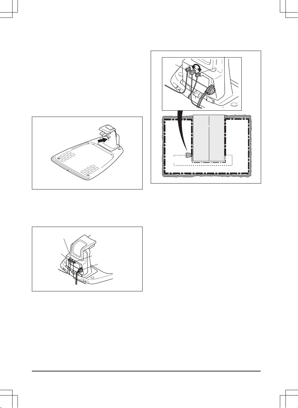
A wire break can be located by gradually halving
the distance of the loop where the break may
have occurred until there is only a very short
section of the wire left.
The following method does not work if
ECO
mode
is activated. Make sure first that
ECO
mode
is turned off. Refer to
ECO mode on page
25
.
1. Check that the indicator lamp in the charging
station flashes blue, which indicates a break
in the boundary loop. Refer to
Indicator lamp
in the charging station on page 39
.
2. Check that the boundary wire connections to
the charging station are properly connected
and not damaged. Check that the indicator
lamp in the charging station is still flashing
blue.
R
GUIDE
L
POWER
3. Switch the connections between the guide
wire and the boundary wire in the charging
station.
Start by switching connection L and GUIDE.
If the indicator lamp is lit with a solid green
light, then the break is somewhere on the
boundary wire between L and the point
where the guide wire is connected to the
boundary wire (thick black line in the
illustration).
GUIDE
L
Guide
To rectify the fault you will need boundary
wire, connector(s) and coupler(s):
a) If the suspected boundary wire is short
then it is easiest to exchange all of the
boundary wire between L and the point
where the guide wire is connected to the
boundary wire (thick black line).
b) If the suspected boundary wire is long
(thick black line) then do as follows: Put L
and GUIDE back to their original positions.
Then disconnect R. Connect a new loop
wire to R. Connect the other end of this new
loop wire at the middle of the suspected wire
section.
42 - Troubleshooting 982 - 003 -
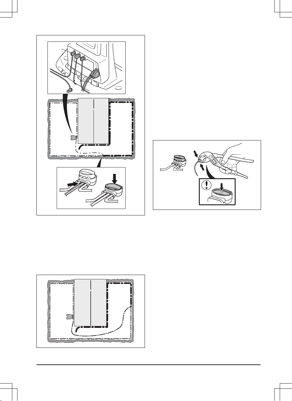
R
If the indicator lamp now is green, then the
break is somewhere in the wire between the
disconnected end to the point where the
new wire is connected (thick black line
below). In that case, move the connection
for the new wire closer to the disconnected
end (roughly at the middle of the suspected
wire section) and check again if the indicator
lamp is green.
Continue until only a very short section of
the wire remains which is the difference
between a solid green light and a flashing
blue light. Then follow instruction in step 5
below.
4. If indicator lamp still flashes blue in step 3
above: Put L and GUIDE back in their
original positions. Then switch R and
GUIDE. If indicator lamp now is lit with a
solid green light then disconnect L and
connect a new boundary wire to L. Connect
the other end of this new wire at the middle
of the suspected wire section. Follow the
same approach as in 3a) and 3b) above.
5. When the break is found, the damaged
section must be replaced with a new wire.
Always use original couplers.
982 - 003 - Troubleshooting - 43

7 Transportation, storage and disposal
7.1 Transportation
The supplied Li-ion batteries obey the Dangerous
Goods Legislation requirements.
• Obey all applicable national regulations.
• Obey the special requirement on package
and labels for commercial transportations,
including by third parties and forwarding
agents.
7.2 Storage
• Fully charge the product. Refer to
To charge
the battery on page 29
.
• Disconnect the product with the ON/OFF
button. Refer to
The ON/OFF button on
page 27
.
• Clean the product. Refer to
Clean the
product on page 30
.
• Keep the product in a dry, frost free space.
• Keep the product with all wheels on level
ground during storage, or use a Husqvarna
wall hanger.
• If you keep the charging station indoors,
disconnect and remove the power supply
and all the connectors from the charging
station. Put the end of each connector wire
in a container with grease.
Note: If you keep the charging station outdoors,
do not disconnect the power supply and the
connectors.
7.3 Disposal
• Obey the local recycling requirements and
applicable regulations.
• For questions about how to remove the
battery, refer to
To replace the battery on
page 32
.
44 - Transportation, storage and disposal 982 - 003 -

8 Technical data
8.1 Technical data
Data 115H
Dimensions
Length, cm / in. 59 / 23
Width, cm / in. 45 / 18
Height, cm / in. 27 / 11
Weight, kg / lbs 9.4 / 20.7
Electrical system 115H
Battery, Lithium-Ion 18 V/2.1 Ah Art.No 584 85 28-01, 584 85 28-02
Battery, Lithium-Ion 18 V/2.0 Ah Art.No 590 21 42-02
Battery, Lithium-Ion 18.25 V/2.0 Ah Art.No 590 21 42-03
Power supply, V/28 V DC 100-240
Low voltage cable length, m / ft 5 / 16.5
Mean energy consumption at maximum use 8 kWh/month in a 1600 m
2
/ 1900 yd
2
work area
Charge current, A DC 1.3
Average mowing time, min 60
Average charging time, min 60
Boundary wire antenna 115H
Operating Frequency Band, Hz 300-80000
Maximum Radio-frequency power, mW @60m
1
<25
1
Maximum active output power to antennas in the frequency band in which the radio equipment
operates.
982 - 003 - Technical data -
45

Noise emissions measured in the environment as
sound power
2
115H
Measured sound power noise level, dB (A) 56
Guaranteed sound power noise level, dB (A) 59
Sound pressure noise level at the operator’s ear,
dB (A)
3
45
The noise emission declarations conforms to EN 50636-2-107:2015
Mowing 115H
Cutting system 3 pivoted cutting blades
Blade motor speed, rpm 2500
Power consumption during cutting, W +/- 20 % 20
Cutting height, cm / in. 5-9 / 2-3.6
Cutting width, cm / in. 22 / 8.6
Narrowest possible passage, cm / in. 60 / 23.6
Maximum slope for work area, % 30
Maximum slope for boundary wire, % 15
Maximum length boundary wire, m / ft. 500 / 1640
Maximum length guide loop, m / ft. 250 / 820
IP-classification 115H
Product IPX5
Charging station IPX5
Power supply IPX4
Bluetooth
®
115H
Operating frequency band, MHz 2400 - 2484
Maximum transmitted power, dBm 8
Husqvarna AB does not guarantee full compatibility between the product and other types of wireless
systems such as remote controls, radio transmitters, hearing loops, underground electric animal
fencing or similar.
2
Noise emissions in the environment measured as sound power (L
WA
) in conformity with EC di-
rective 2000/14/EC and New South Wales legislation (Protection of the Environment Operations
Regulation 2017, Noise Control). The guaranteed sound power level includes variation in pro-
duction as well as variation from the test code with 1-3 dB(A). Noise emission data can be found
on the rating label and in the Technical data chapter.
3
Sound pressure noise uncertainties K
pA
, 2-4 dB (A)
46 - Technical data 982 - 003 -

The products are made in England or the Czech Republic. See information on the rating plate. Refer to
Introduction on page 3
.
8.2 Registered trademarks
The
Bluetooth
®
word mark and logos are registered trademarks owned by
Bluetooth SIG, inc.
and any
use of such marks by Husqvarna is under license.
982 - 003 - Technical data -
47

9 Warranty
9.1 Warranty terms
Husqvarna
®
warranty covers this product's
functionality for a period of 2 years from date of
purchase. The warranty covers serious faults
relating to materials or manufacturing faults.
Within the warranty period, we will replace the
product or repair it at no charge if the following
terms are met:
• The product and the charging station may
only be used in compliance with the
instructions in this Operator’s Manual. This
manufacturer's warranty does not affect
warranty entitlements against the dealer/
retailer.
• End-users or non-authorized third parties
must not attempt to repair the product.
Examples of faults which are not included in the
warranty:
• Damage caused by water seepage from
using a high-pressure washer, or from being
submerged under water, for example when
heavy rain forms pools of water.
• Damage caused by lightning.
• Damage caused by improper battery storage
or battery handling.
• Damage caused by using a battery that is
not a Husqvarna original battery.
• Damage caused by not using Husqvarna
original spare parts and accessories, such
as blades and installation material.
• Damage to the loop wire.
• Damage caused by non-authorized
changing or tampering with the product or its
power supply.
The blades and wheels are seen as disposable
and are not covered by the warranty.
If an error occurs with your Husqvarna product,
please contact Husqvarna customer service for
further instructions. Please have the receipt and
the product’s serial number at hand when
contacting Husqvarna customer service.
48 - Warranty 982 - 003 -
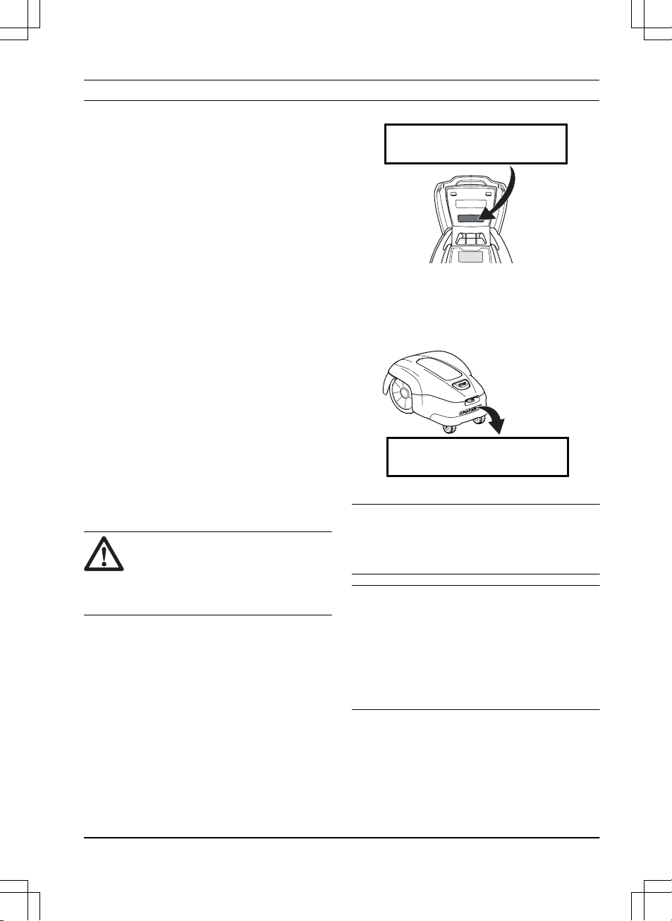
10 Applicable to US/CA market
10.1 Supplier's Declaration of
Conformity
Issuer: Husqvarna AB, Drottninggatan 2, S-561
82 Huskvarna, Sweden
www.husqvarnagroup.com.
Responsible party: Husqvarna Professional
Products, Inc. 9335 Harris Corners Parkway
Suite 500 Charlotte, NC 28269 United States
U.S. Contact information: James McNew,
Manager Product Compliance, Telephone: +1
704 597 5000.
10.2 Compliance requirements
FCC ID: ZASHQ-BLE-1A (the Bluetooth
®
module).
The Bluetooth
®
module is located on the
HMIboard (PCBA) in the upper chassis. It must
only be accessed by an authorized service
technician.
The device complies with part 15 of the FCC
Rules. Operation is subjected to the following 2
conditions:
1. This device may not cause harmful
interference.
2. This device must accept any interference
received, including interference that may
cause undesired operation.
WARNING: To comply with RF
exposure requirements, please
maintain a separation distance of at
least 20 cm/ 7 inches from any part of
the product.
Models with a hatch: The supplied label shall be
attached to the product according to figure below.
This device contains the module
FCC ID: XXX1YYYY2ZZZ
Models without a hatch: The supplied label shall
be attached to the product according to figure
below
This device contains the module
FCC ID: XXX1YYYY2ZZZ
Note: Changes or modifications made to this
equipment not expressly approved by Husqvarna
may void the FCC authorization to operate this
equipment.
Note: This device complies with Part 15 of the
FCC Rules [and with Industry Canada
licenceexempt RSS standard(s)]. Operation is
subject to the following two conditions: this
device may not cause harmful interference, and
this device must accept any interference
received, including interference that may cause
undesired operation.
982 - 003 - Applicable to US/CA market - 49
Note: This equipment has been tested and found
to comply with the limits for a Class B digital
device, pursuant to part 15 of the FCC Rules.
These limits are designed to provide reasonable
protection against harmful interference in a
residential installation. This equipment generates,
uses and can radiate radio frequency energy
and, if not installed and used in accordance with
the instructions, may cause harmful interference
to radio communications. However, there is no
guarantee that interference will not occur in a
particular installation. If this equipment does
cause harmful interference to radio or television
reception, which can be determined by turning
the equipment off and on, the user is encouraged
to try to correct the interference by one or more
of the following measures:
• Reorient or relocate the receiving antenna.
• Increase the separation between the
equipment and receiver.
• Connect the equipment into an outlet on a
circuit different from that to which the
receiver is connected.
• Consult the dealer or an experienced
radio/TV technician for help.
WARNING: Cancer and Reproductive
Harm - www.P65Warnings.ca.gov
50 - Applicable to US/CA market 982 - 003 -

982 - 003 - Applicable to US/CA market - 51
www.husqvarna.com
AUTOMOWER
®
is a trademark owned by Husqvarna AB.
Copyright
©
2019 HUSQVARNA. All rights reserved.
Original instructions
1140739-26
2019-05-16