Loading ...
Loading ...
Loading ...
7
Installation Instructions
STEP 8 (cont):
Installation of the UVC Main Board
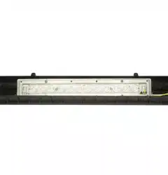
7DNHWKH9UHOD\ZLUHKDUQHVVIURPWKHNLWSDFNDJLQJ7KLVZLOOKDYHDQRUDQJHFRQQHFWRUZLWKUHGDQGZKLWH
ZLUHV&RQQHFWWKHZLULQJKDUQHVVRUDQJHFRQQHFWRUWRWKHQHZPDWLQJFRQQHFWRURQWKH89&PDLQERDUG
14. Route 240V relay wire harness down the left side of the main board.
15. Align the UVC main board and engage the white retaining pin to hold the main board in place.
16. Reconnect the indoor fan motor wiring harness connector.
17. Install the main board cover.
18. Secure the main board cover using the two 1/4” screws removed earlier.
19. Reconnect the thermistor wiring harness.
Wiring Harness
New orange UVC
VSHFL¿FWHUPLQDO
STEP 9:
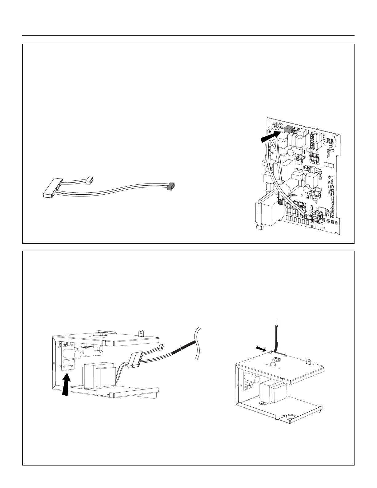
Install the UVC Junction Box
1. Remove the junction box assembly from the kit packaging. On models that use wall plugs, the strain relief knockout
will need to be removed.
2. Install the large white connector from the new 240V relay harness to the matching side in the junction box.
,QVWDOOWKHVPDOOWZRZLUHZKLWHFRQQHFWRUWRWKHUHFWL¿HUERDUGORFDWHGLQWKHMXQFWLRQER[DVVHPEO\
4. Dress the 240V relay harness wiring by snapping the wire tie into the mating hole on the back left corner of the
junction box.
5HFWL¿HUERDUG
Holes for wire
KDUQHVV]LSWLH
Loading ...
Loading ...
Loading ...